patent · US4144716
Solar powered engine and tracking system
20 March 1979
Page 1 — bibliographic record
United States Patent 19 (11) 4,144,716 Chromie (45) Mar. 20, 1979 (54 SOLAR POWERED ENGINE AND Attorney, Agent, or Firm-Frank D. Gilliam
TRACKING SYSTEM
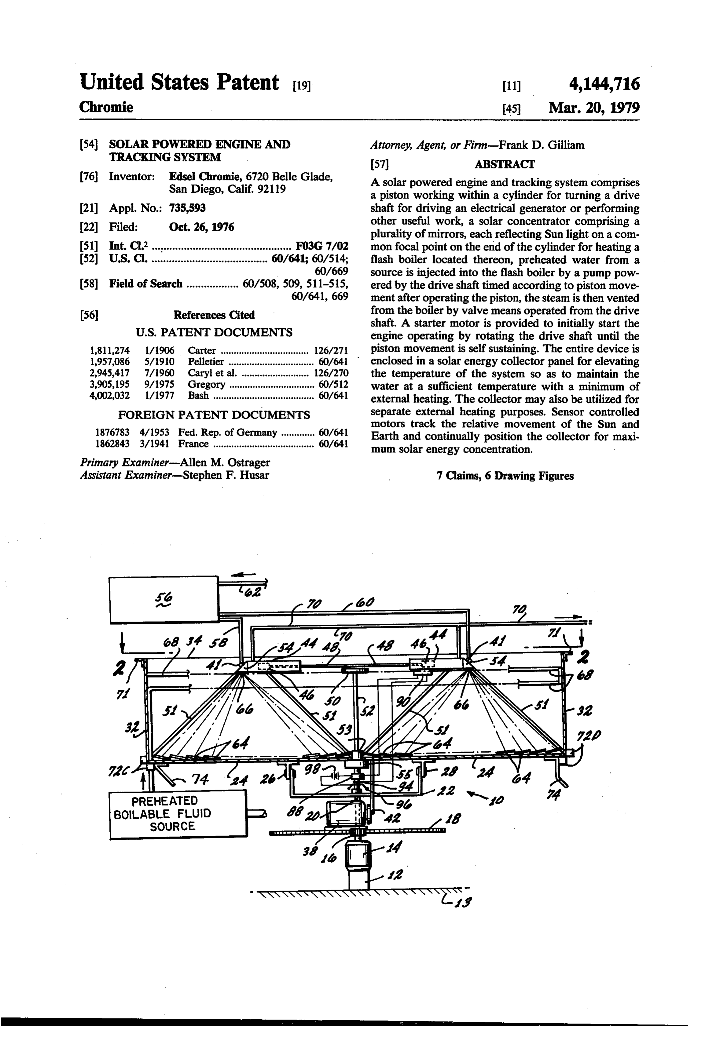
76 Inventor: Edsel Chromie, 6720 Belle Glade, A solar powered engine and tracking system comprises San Diego, Calif. 92119 a piston working within a cylinder for turning a drive 21 Appi. No.: 735,593 shaft for driving an electrical generator or performing 22 Filed: Oct. 26, 1976 other useful work, a solar concentrator comprising a plurality of mirrors, each reflecting Sun light on a com 5) Int. C.’................................................ FO3G 7/02 mon focal point on the end of the cylinder for heating a 52 U.S. C. ........................................ 60/641; 60/514; flash boiler located thereon, preheated water from a 60/669 source is injected into the flash boiler by a pump pow 58 Field of Search .................. 60/508, 509, 511-515, ered by the drive shaft timed according to piston move 60/641, 669 ment after operating the piston, the steam is then vented 56 References Cited from the boiler by valve means operated from the drive
shaft. A starter motor is provided to initially start the engine operating by rotating the drive shaft until the 1,811,274 1/1906 Carter .................................. 126/271 piston movement is self sustaining. The entire device is 1957,086 5/1910 Pelletier ................................. 60/641 enclosed in a solar energy collector panel for elevating 2,945,417 7/1960 Caryl et al... ... 126/270 the temperature of the system so as to maintain the 3,905,195 9/1975 Gregory ................................. 60/512 water at a sufficient temperature with a minimum of 4,002,032 l/1977 Bash ....................................... 60/641 external heating. The collector may also be utilized for FOREIGN PATENT DOCUMENTS separate external heating purposes. Sensor controlled motors track the relative movement of the Sun and 1876783 4/1953 Fed. Rep. of Germany ............. 60/641 Earth and continually position the collector for maxi 1862843 3/1941 France ....................................... 60/641 mum solar energy concentration.
Primary Examiner-Allen M. Ostrager
Assistant Examiner-Stephen F. Husar 7 Claims, 6 Drawing Figures
PREHEATED
BOLABLE FLUID
SOURCE
Page 2
Drawing sheet — no readable text.
Page 3
Drawing sheet — no readable text.
Page 4
Drawing sheet — no readable text.
Page 5
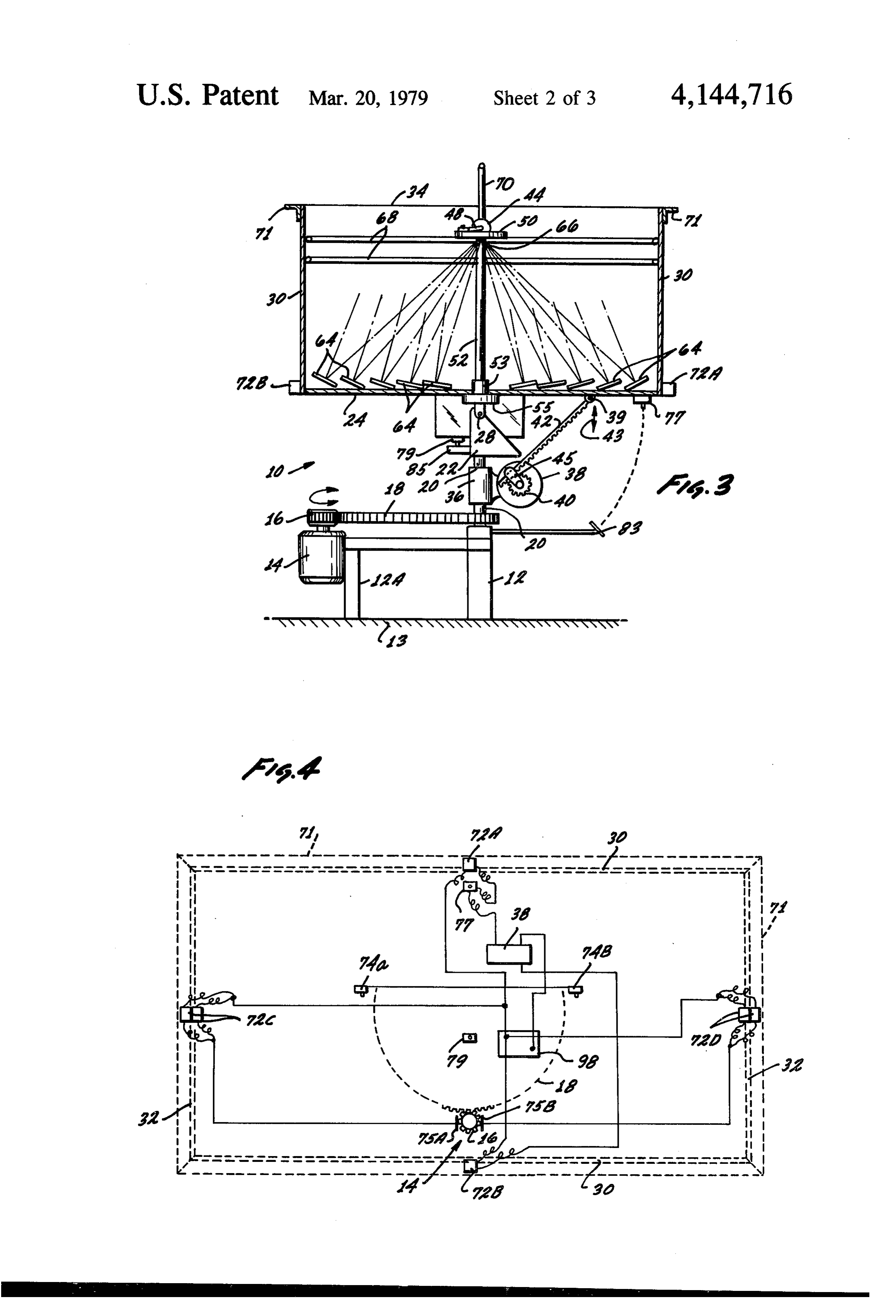
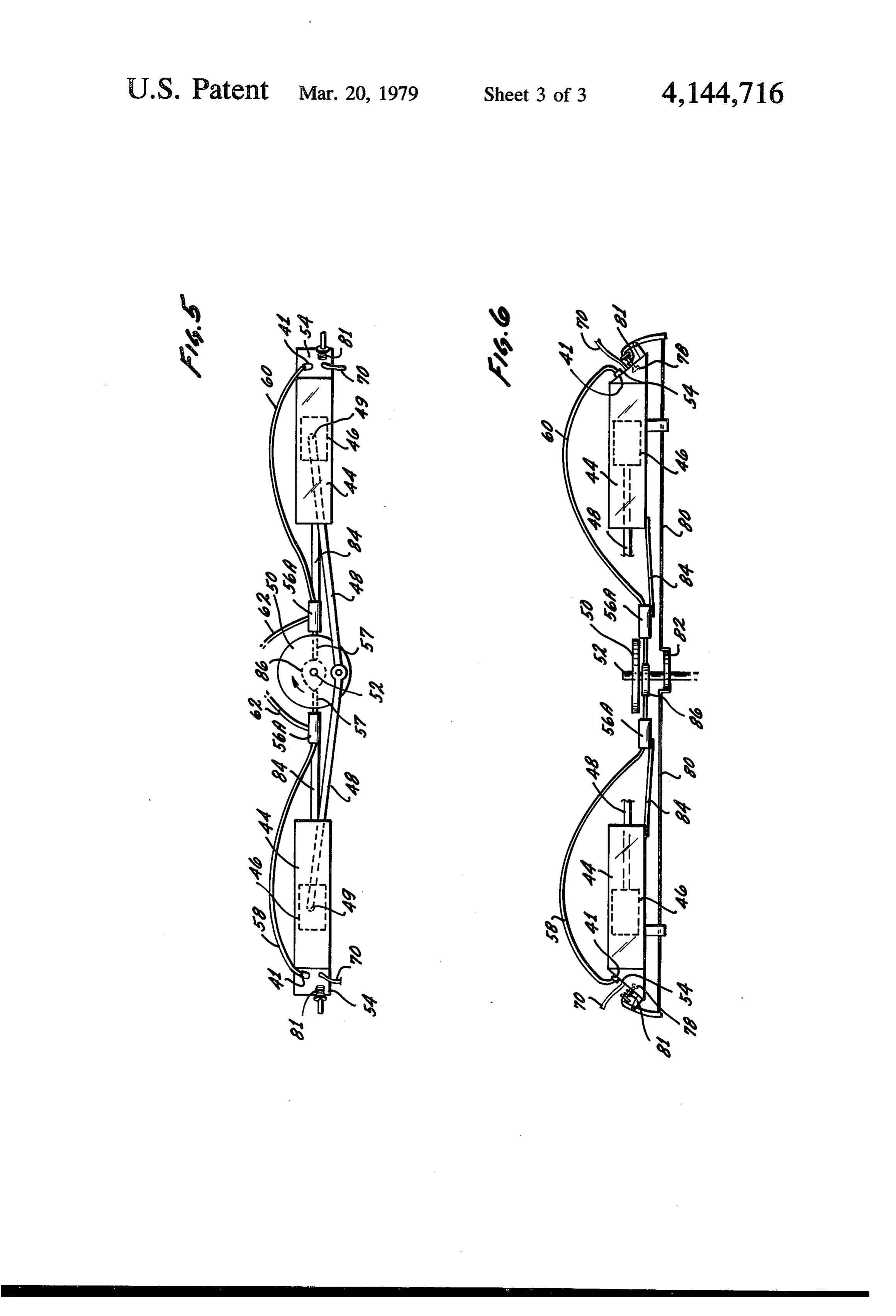
FIG. 4 is a diagrammatic view of the electrical wiring
SOLAR POWERED ENGINE AND TRACKING of the solar tracking mechanism of the invention; SYSTEM FIG. 5 is a plan view, partially in phantom, of the
BACKGROUND OF THE INVENTION
injector pumps and their operating mechanism; and
FIG. 6 is a side view of the FIG. 5 showing further
The present invention relates to steam engines and including the valves and their operating mechanism. more specifically to a flash boiler operated steam engine DESCRIPTION OF THE PREFERRED where the principal heat is supplied by a solar concen EMBODIMENT trator confined within a solar energy collector.
There are several prior art devices that utilize solar 10 The same reference numerals are used throughout the heat to operate steam engine devices. Figures and specifications to depict the same element or U.S. Pat. No. 1,424,932 teaches the use of a steam part.
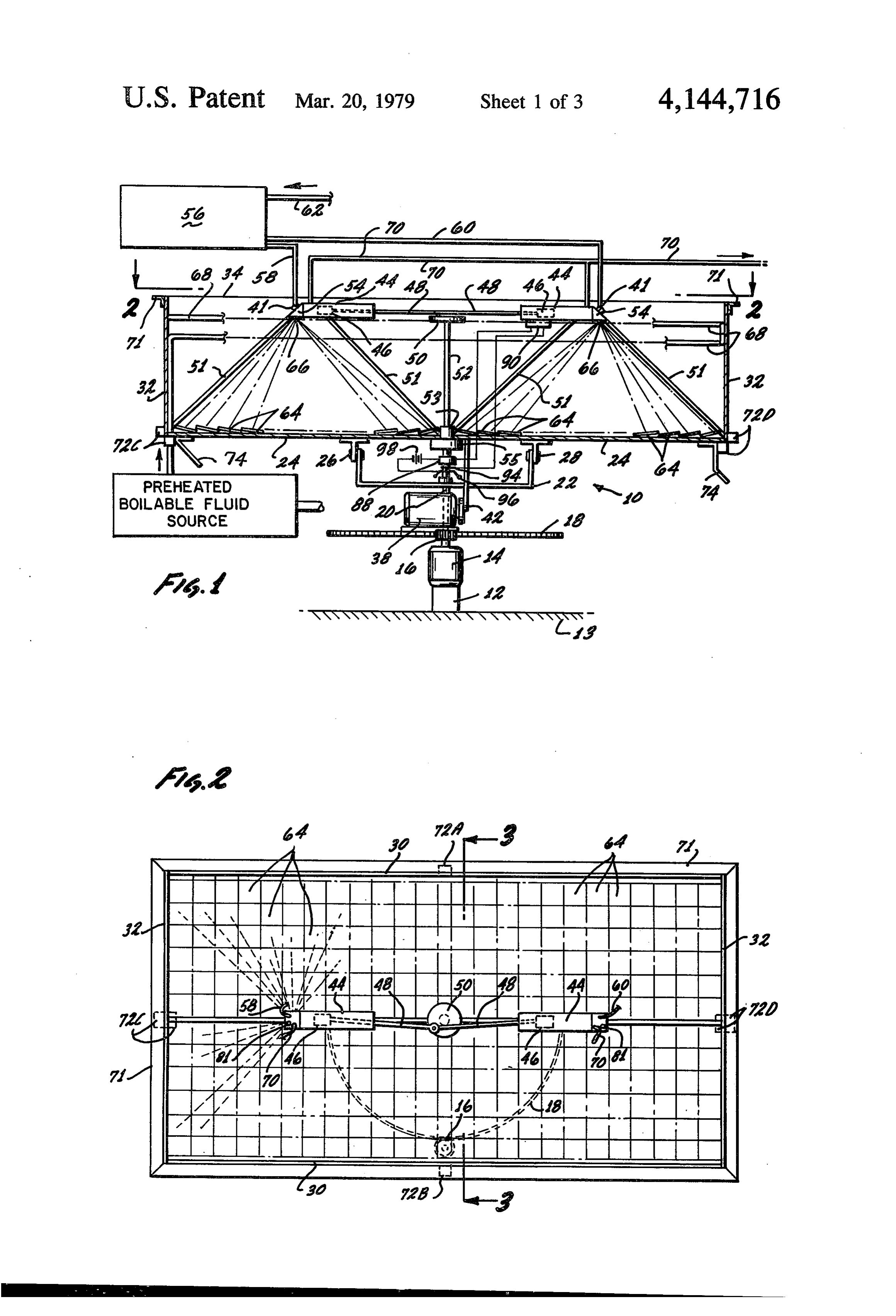
engine boiler positioned at the apex of a parabolic re Referring now specifically to FIGS. ii, 2 and 3, a flector system. This system teaches the forming of a combination solar light energy collector and concentra parabolic surface and a plurality of different focal points 15 tor i0 is shown. The apparatus is supported by a base around the surface of the steam boiler. 12, 12a attached to a surface positioned on the Earth 13, There is no means provided for positioning of the an example would be a support member buried in the device to ensure maximum heat from the Sun during ground to a sufficient depth and having sufficient mass Sun/Earth relative movement. to easily support the apparatus 10. The base 2a sup U.S. Pat. No. 1,386,781 teaches a solar concentrator ports a motor 14 which drives a gear 16 attached to the device where Sun tracking is performed by a clock motor shaft. Gear 16 drives a larger semi-circular gear motor mechanism. 18. The gear 18 is fixedly attached to shaft 20 which is U.S. Pat. No. 3,892,433 teaches a plurality of curved fixedly attached to the collector bracketry 22. Shaft 20 reflectors positioned to direct solar energy to a plurality is rotatably attached to the base member 12 thus allow of focal points on a steam generator. The positioning of 25 ing the base free rotational movement relative thereto. the reflectors requires an equal plurality of optical sen Pivotly attached to bracketry 22 is the collector bot sors and sensor-servo mechanisms. tom member 24. The bottom member 24 is allowed to These prior art systems are complicated, inefficient pivot with respect to base member 12, 12a at its pivotal and economically expensive to produce. attachment points 26, 28. The collector further includes 30 side members 30 and end members 32. The lid 34 of the
SUMMARY OF THE INVENTION
collector is constructed of a light admitting material,
The present invention provides an efficient, uncom such as, but not limited to, glass or plexi-glass. The lid, plicated and reasonably inexpensive means for convert sides, ends and bottom make up an enclosure for the ing solar light energy into useful work. The Sun's light collection of solar energy. Insulation (not shown) is rays are concentrated at a single focal point on a flash 35 used to contain the heat within the collector, steam boiler to maximize the heat at the boiler. The A bracket 36 fixedly secured to shaft 20 supports a operating mechanism is enclosed in a solar heat collec second motor 38. The rotation of motor 38 drives a gear tor panel so as to elevate the temperature of the entire 40. A gear rack 42 is pivotly attached at its upper end 39 system to provide increased operational efficiency. The to the collector bottom 24. The opposite end of the rack collector tracks the relative movement of the Sun and 42 is held in sliding engagement by bracket 45 which is Earth by sensor controlled motor means so as to main free to pivot with respect to gear 40 and allows rack 42 tain the maximum heat at the flash steam boiler during to freely move therein when the gear 40 is caused to Sun light hours. rotate. It can be readily seen that when the motor ro The main object of this invention is to utilize the heat tates, the rack will translate causing the collector to tilt energy of the Sun's rays in the production of electrical 45 downwardly from its FIG. 1 and 3 position. Along power. arrow 43 within the limits of the length of the gear rack Another object of this invention is to devise an appa 42.
ratus of extremely high efficiency which will obtain the Positioned within the upper portion of the collector maximum result from the Sun's rays for the maximum are two cylinders 44 which contain pistons 46 slidably time period. 50 engaged therein. The pistons are each connected to a A further object of the invention is to provide a solar connecting rod 48 by a conventional piston pin 49 (see energy concentrator occupying a minimum of vertical FIG. 5) so that the connecting rod is free to move later space. ally with respect to the longitudinal movement of the The foregoing objects, features, advantages and re piston. The ends of the connecting rods remote from sults of the present invention, together with various 55 their piston attached ends are pivotly connected to a other objects, advantages, features and results thereof central disk 50 (see the various figures). The disk 50, in which will be evident to those skilled in the solar energy some instances, will be required to have sufficient mass art in the light of the disclosure, may be achieved with to act in the manner of a fly wheel. the exemplary embodiment of the invention illustrated It can be readily seen that as the pistons move within in detail hereinafter. 60 their respective cylinders, the disk 50 will rotate.
DESCRIPTION OF THE DRAWINGS
The disk 50 is secured to the end of a drive shaft 52 which passes through a slip guide 53 and is attached to
FIG. 1 is a partially cutaway side view of the appara a generator 55 for the production of electricity as the tus of the invention; pistons move. It should be understood that drive shaft FIG. 2 is a plan view of the reflective surface of the 65 52 may be utilized to perform any type of useful work solar concentrator of the invention; and is not limited to the production of electricity. FIG.3 is a partially cutaway end view of the appara The cylinders are supported by the lower surface 24 tus of the invention taken along lines 3-3 of FIG. 1; by any convenient manner so as to block as little of the
Page 6
Sun's rays striking the reflective surfaces as practical. site side of the collector from striking their light sensi Brackets 51 are an example of how this may be accom tive surface. A pertusion or lip 71 is positioned around plished. the upper surface of the collector panel for shielding the The generator 55 is secured either to the bracketry various sensors 72a, 72b, 72c and 72d which are adja 22, the bottom 24 of the collector or through a support cent thereto. The pertusion or lip has sufficient width to ing bearing on shaft 52, so that it can tilt or turn with the aid in shielding the Sun's light rays from its adjacent collector panel when motors 38 and 14 are energized. sensor when the collector is properly positioned with At one end of cylinders 44 is positioned flash steam respect to reflecting the Sun's light rays from reflectors boiler 54. A pump 56 for pumping the pre-heated water 64 to focal point 66.
or any suitable expandable fluid through the injectors 41 10 The sensors 72c, 72d are interconnected to motor 14 (shown in one variation) is interconnected to each of the so that when light strikes the sensors, the motor will be two flash steam boilers through high pressure conduit activated in a rotational direction to turn the collector 58, 60. The inlet to the pump 56 is connected to a source until the light no longer strikes that sensor. The sensors of preheated water (hereinafter discussed) through con 72a and 72b are positioned so that when they receive duit 62. The output of the pump supplies water under 15 light rays from the Sun, they cause motor 38 to operate increased pressure to a conventional injector 41, such as and tilt the collector until that sensor no longer receives those used in the diesel engine art, which injects this the light rays.
water into the flash steam boiler 54. Both motors operate in either rotational direction A plurality of flat recti-linear reflective surfaces 64 depending upon their requirement and hold their last are supported by and cover the inner surface of bottom 20 activated position. The motors are either very slow , 24. The reflective surfaces are positioned and held in rotating, such as a clock motor, or are connected to a place so that each will reflect the light of the Sun shin speed step down gear box (not shown) to reduce their ing thereon to a single focal point 66 on the lower sur speed to that suitable for the above requirement. face of the flash steam boiler 54. It should be noted that A pair of normally closed switches 77, 79 are wired in the reflective surfaces shown are of sufficient area quan 25 series with sensors 72a, 72b respectively, which are in tity to be equally divided between two focal points to series with motor 38 and battery 98. The sensors have operate two flash steam boilers 54. separate series circuits. Switch 77 is depressed when the The reflective surface may be glass mirrors, however, bottom 24 is rotated to its maximum downward position the invention is not limited in this manner as any suit causing the switch to engage bracket 83 attached to able reflective surface may be utilized equally as well to 30 base 12. When contact is made, switch 77 opens the practice the invention. series circuit between sensor 72a and the motor causing The source of preheated water supplied to the pump the motor to be inoperative. When the bottom 24 is in its 56 may be provided by the coil of conduit 68 positioned FIG. 1 and 3 position, switch 79 engages bracket 85 and within the aforementioned collector, from any external causes motor 38 to be inoperative in the opposite direc heating means (not shown) or from a combination of the 35 tion. This is a safety feature to prevent burn out of the coil of conduit 68 and additional heat from an external motor. A similar pair of series circuits are provided with source. It should be apparent that the heated water from switches 74a and 74b that engage brackets 75a and 75b the coil of conduit 68 may be used to supply heat re respectively to serve the same purpose as switch 77, 79 quirements separate from the engine, as a conventional for apparatus rotating motor 14.
solar heater. The engine exhaust steam may be vented It should be obvious that when conduit 70 is con to atmosphere through conduit 70 in an open cycle nected external of the collector that a flexible conduit system where the input to the coil of conduit 68 is sup must be attached to its end to allow freedom of rota plied from an external source of water. Ideally, the tional and tilting movement with the collector as re engine steam exhaust is utilized in a closed system quired. When operating as a closed system as hereinbe wherein the steam passes through an external heat ex 45 fore mentioned the conduit 70 may be a flexible conduit. changer where it is used for the heating of building, Referring now specifically to FIGS. 5 and 6, the operating refrigeration apparatus or the like. The re valves 78 are actuated by the operation of their associ moval of heat from the steam in this manner acts as a ated push rods 80. Push rods 80 bear against cam lobe 82 condenser to cool the steam back to a water which is secured to drive shaft 52 for rotation therewith. Springs then returned to one end of the coil of conduit 68, is 50 81 return the valves to a normally closed position. The re-heated, and again supplied to pump 56 through con valves 78 are operable in a conventional manner to open duit 62 (see FIG. 3). If, in a closed system, the use of the at the required time so as to vent each flash steam boiler exhaust heat is not desired, a sufficiently long conduit 70 54 when its associated piston reaches the end of its would be required to lower the steam temperature or a power stroke. The first showing of pump 56 was a block conventional condenser may be employed, in series 55 showing of a single conventional device well known in between the engine exhaust and the coil of conduit 68. the diesel engine art or the like. Separate single pumps Referring now to FIGS. 1-4, on each side 30, external 56a are shown in FIGS. 5 and 6 as another example of of the collector, are positioned light sensing elements a pump system that may be utilized equally as well to 72a, 72b, on each end 32 are positioned a pair of sensors practice the invention. The two pumps 56a as 56 may be 72c and 72d, in some applications a pair of sensors 72c supported by the cylinder through bracket 84 as an and 72d may be required (see FIG. 4). These sensors example, however, support means from the bottom 24 may take many forms, such as, but not limited to, sele (not shown) may be utilized equally as well to practice nium photo cells, catalog number 276-115 and light the invention. The pumps 56a are actuated by means of activated silicon controlled rectifiers, catalog number cam 86 operating push rods 57. The pump actuators are 276-1095, both are manufactured by Archer for Radio 65 internally biased to bear against the cam 86 at all times. Shack Inc., or the like. Referring now specifically to Referring now specifically to FIG. 1, in some circum FIG. 1, a shield 74 is positioned adjacent to the sensors stances a starter systems will be required to initially turn 72c and 72d preventing direct Sun light from the oppo shaft 52 so as to provide rotation of cam 86 to actuate
Page 7
the-pumps 56a, The starter system includes a starter When the flash steam boiler 54 reaches a predeter motor 88 having its rotor co-axial and attached with (mined temperature that is sufficient to maintain piston drive shaft 52. Actuation of the starter motor will turn displacement and drive shaft rotation switch 90 will shaft. 52 at sufficient speed - to properly actuate the energize the starter motor 88. The speed of rotation of pumps 56a. & the starter motor is sufficient to cause the pistons to The circuit for the starter motor includes a tempera translate at an operable speed taking in consideration ture sensitive switch 90 positioned perferrably adjacent the load of the generator, pumps, and valves, but not one of the flash steam boilers and a second switch com sufficient to turn the fly weight 96 fast enough to disen prising an electrical conductive slip ring 94 positioned gage slip ring 94. When the normal operation of the above a centrifical fly weight 96 which is attached to O device increases the speed of the pistons and drive shaft, the drive shaft 52. When drive shaft 52 turns the fly the fly weight 96 will then rise and disengage the slip weight 96 at sufficient speed, it is caused to move away ring 94 and the starter motor circuit will then be de from slip ring 94 which in turn opens the starter motor energized.
circuit. Switch 90 and slip ring switch 94 are wired in As relative movement between the Sun and Earth is series with the starter 88 and the battery 98 so that both 15 detected by the Sun's rays again striking the sensor or are required to close to enable the starter motor to sensors, the operate. Therefore, the starter motor will run only reposition thepositioning motors will be activated to when the engine operation does not rotate shaft 52 at a will maintain their same focalthat collector so the reflective surface point on the lower surface speed that opens slip ring switch94 and the temperature is sufficient to close switch90. If either do not occur, in 66 to provide maximum heat collection. the absence of the Sun, the starter motor will remain As is well known for servo-systems, some hunting inoperative. The power to operate the starter motor is between the motors directional rotation may occur but supplied, for example, by battery 98. It should be under a slightly enlarged focal surface will allow the reflec stood that in some instances, it will be advantageous to tion to be positioned on the lower surface during nor combine the starter motor and generator into a single 25 mal hunting of the positioning system. device in a known manner. The positioning of the collector will continue to It should be understood that although two steam occur as long as Sun light is present. Absence of Sun engine piston and cylinder combinations are shown and light will cause the positioning to stop. When the Sun discussed, that a single piston and cylinder steam engine light is again present, a similar sequence of events will or more than two piston and cylinder combinations may 30 occur bringing the positioning apparatus into operation. be connected to the same drive shaft 52 depending on When the flash boiler temperature is such that the power requirements and space available. Each steam pistons will cease to operate the switch 90 circuit is engine would require a separate concentrator. open preventing operation of the starter circuit as with OPERATION OF THE PREFERRED the positioning apparatus, return of Sun light will pro 35 vide a proper sequence of events bringing the engine
The apparatus, as described, is positioned with its side The invention may be embodied in other specific 30 having motor 38 in a generally southernly direction forms without departing from the spirit or essential and ends 32 in an east/west direction. characteristics thereof. The present embodiment is, With the apparatus properly positioned with respect therefore, to be considerated in all aspects as illustrative to the Sun, the rays will be reflected by each of the and not restricting, the scope of the invention being mirror segments 64 to their appropriate focal point 66 indicated by the appended claims rather than by the on the bottom surface of the flash steam boiler 54. foregoing description, and all changes which come Assume that at a given time the Sun has not been within the meaning and range of equivalency of the visible for a period of time, and now reappears, the 45 claims are therefore intended to be embraced therein. temperature of the collector is reduced below a pre What is claimed as new and useful and desired to be determined level and the Sun's rays will not be directed secured by U.S. Letters Patent is:
to focal point 66 because of relative movement between 1. A solar light energy powered engine comprising: the Sun and Earth. The Sun's light rays will strike sen a cylinder having a piston slidably engaged therein, sors 72a, 72b, 72c, and 72d that are exposed to direct 50 said piston forming a pressure seal with the inner Sun light, activating the motors 38 and 14 to position walls of said cylinder interconnected to a drive the panel to focus on focal point 66. shaft for providing rotational forces thereto; In the afternoon, the sensors on the North and West would likely be exposed and in the morning, likely the a flash boiler is provided at one end of said cylinder, South and East sensors would be exposed. The sensor 55 said flash boiler having at least one flat surface; or sensors receiving the Sun's light rays will cause their a solar light energy concentrator comprising a plural associated motor to operate sensors 72a and 72b in a ity of recti-linear reflective surfaces supported on a rotational direction in which that sensor is directed substantially flat base member for concentrating away from direct contact with the Sun's rays and sensor solar light energy on a single focal point that com 72c will cause counterclockwise rotation while 72d will prises substantially the entire area of said flat sur cause clockwise rotation of motor 14. When the sensor face of said flash boiler; is shielded from the Sun's rays, then its associated motor a source of pre-heated boilable fluid; will stop and maintain its last rotational position. If a a pump injector means for selectively admitting a second sensor 72 has been activated, a similar operation predetermined quantity of pre-heated boilable fluid will occur. When both of the motors are stopped, then 65 from said source into said flash boiler adjacent said the rays of the Sun will again be directed from the focal point at an elevated pressure; reflectors to the focal point 66 on the bottom surface of valve means for selectively venting said cylinder of the flash steam boiler 54. said boilable fluid; and
Page 8
said solar light energy engine is substantially con 4. The invention as defined in claim 1, wherein a plurality of piston and cylinder combinations and solar tained within a solar energy collector which pre concentrators are utilized.
heats the boilable fluid from said source, 5. The invention as defined in claim 4, wherein said 2. The invention as defined in claim 1, wherein said plurality of pistons are interconnected to said drive shaft.
recti-linear reflective surfaces are conventional flat 6. The invention as defined in claim 1, wherein said glass mirrors. solar energy collector comprises a base member as a bottom surface, side walls perpendicular to said base 3. The invention as defined in claim 1, wherein con 10 member and an upper surface substantially parallel to duit means interconnects said valve means with said said base member, said upper surface being transparent pump and injector means and a heat removing means to 7.light. The invention as defined in claim 1, wherein starter and said pre-heating means are connected in series be means is provided for starting said engine.
tween said valve means and said pump. 15
Provenance
- Collection
- Cited prior art
- Original PDF
- patentimages.storage.googleapis.com →
- Filed
- 1976-10-26
- Pages
- 8
- Method
- pdftotext (the PDF's own text layer) + pdftoppm 300dpi page scans
- Source
- Google Patents bibliographic record
- Granted
- 1979-03-20
- Inventors
- Edsel Chromie
- Transcribed from
- patentimages.storage.googleapis.com →