patent · US4016837
Vapor intake system for internal combustion engines
12 April 1977
Page 1 — bibliographic record
United States Patent to 11, 4,016,837 Wentworth, Jr. 45 Apr. 12, 1977 (54) WAPOR ENTAKE SYSTEM FOR INTERNAL 1,734,872 1 1/1929 Nash et al. ...................... 23/25 A COMBUSTION ENGINES 2,122,414 7/1938 Foster .............................. 123/25 A 2,890,029 6/1959 Hicks ....... ... 261/18 A 76 Inventor: Fred A. Wentworth, Jr., 20 Heights 3,044,453 7/1962 Hoffmann ... 123125 B Road, Stratham, N.H. 03885 3,716,040 2/1973 Herpin.......................... 123,125 RX 3,749,376 7/1973 Alm et al. ...................... 12311 A X 22) Filed: Oct. 17, 1974 3,767,172 10/1973 Mills ............................ 123125 RX
Primary Examiner-C. J. Husar
Related U.S. Application Data Assistant Examiner-Era S. Lazarus (63) Continuation-in-part of Ser. No. 430,252, Jan. 2, Attorney, Agent, or Firm-Thomas N. Tarrant
52 U.S. Cl. ............................ 123/25 R; 261/18 A .
51 int. Cl'......................................... F02D 19/00 A system including a water container, a connecting line 58 Field of Search ............. 123/25 R, 25 A, 25 L, from the top of the water container to the air intake of 123/25 B, 1A, 25 E, 25 G; 261/18 A, 30, an internal combustion engine, a blower, and a line DIG. 66; 43114 connected to receive positive air pressure from the blower and conduct it to a point below the surface of (56) References Cited water in the water container.
UNITED STATES PATENTS
1,618,602 2/1927 Meyers et al. ................... 123125 A 8 Claims, 3 Drawing Figures
Page 2
Drawing sheet — no readable text.
Page 3
Thus, it is an object of the invention to provide a
VAPOR INTAKE SYSTEM FOR INTERNAL novel intake water vapor system for internal combus COMBUSTON ENGINES tion engines that is responsive to pressure from a CRoss REFERENCE TO RELATED blower driven proportional to engine speed. APPLICATIONS Further objects and features of the invention will become apparent upon reading the following descrip
The present application is a continuation in part of tion together with the drawings. my prior pending application, Ser. No. 430,252 filed
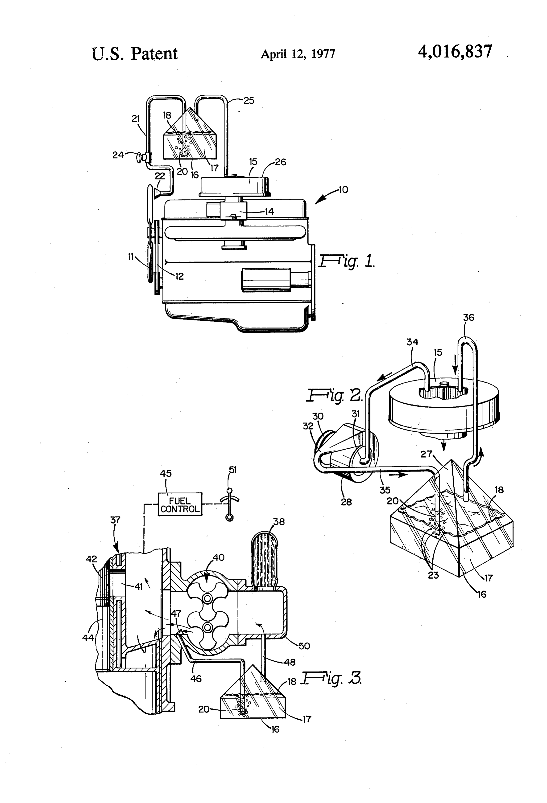
Jan. 2, 1974 entitled Fuel Catalyzer now U.S. Pat. No. BRIEF DESCRIPTION OF THE DRAWING 3,867,819. 10 FIG. 1 is a perspective view of a gasoline engine
BACKGROUND OF THE INVENTION
incorporating the inventive intake vapor system.
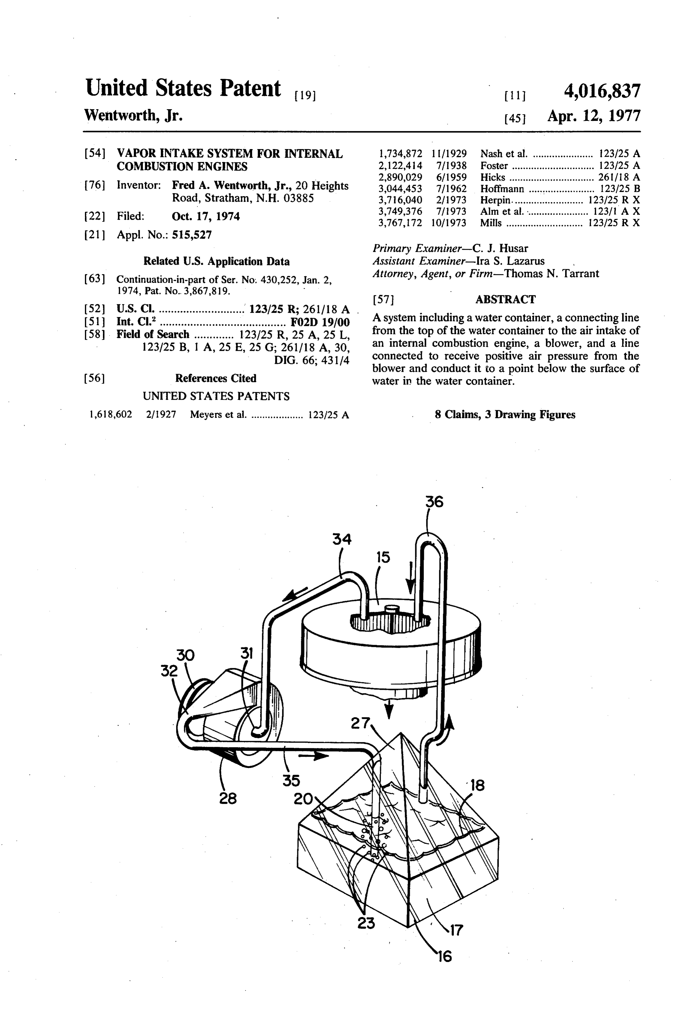
FIG. 2 is a perspective view of an embodiment of the 1. Field of the Invention invention using a closed loop system on a gasoline The present invention relates to energy boosters for engine.
fossil fuel combustion systems and in particular to such 15 FIG. 3 is a perspective view of an embodiment of the boosters providing controlled water vapor content. invention utilizing the intake blower of a blown diesel 2. Description of the Prior Art as the blower.
It is well known that high humidity can improve the DESCRIPTION OF THE PREFERRED performance of an internal combustion engine. Various 20 EMBODIMENTS water injectors have been marketed with allegations of improved economy and performance for automobile Conventional gasoline engine 10 as depicted in FIG. engines. Commercial oil burners have long utilized 1 has carburetor 14 which receives outside air through steam to atomize oil for improved combustion. air cleaner 15. Engine 10 also has radiator cooling fan In all of these arrangements, any additional energy 25 11 connected to one end and driven through fan belt 12 produced must be due either to energy conversion from by the engine crank shaft.
the additional mass provided or energy due to a more Liquid container 16, depicted as a transparent plastic efficient or complete conversion of the fossil fuel. With container having a pyramidal top, carries a supply of water as the agent, either of these is possible and some water 17 with supernatant nonmiscible layer 18. While combination is probable in most cases. Mostly, substan 30 layer 18 may be oil, one specific reason for its use is to tial quantities of moisture addition have been used. In prevent natural evaporation into or absorption from automotive engines, this has usually resulted in short the enclosed airspace. Thus, many nonmiscible liquids engine life, burned valves and other difficulties. The can be used. The thickness of layer 18 and the viscosity cost of accessory equipment has apparently been a of the liquid in layer 18 are selected to provide a layer deterrent in home heating service. 35 that will maintain some integrity in the presence of It is also known that water vapor can act as a cata turbulence due to bubbling and at the same time will lyzer for combustion. See Van Nostrand's Scientific not unduly impede bubbling action. The vapor pressure Encyclopedia, fourth edition, page 1501. Useful imple of the liquid in layer 18 should be negligible. A thick mentation of this phenomenon is strangely lacking in ness for layer 18 of about one to five millimeters and an most commercial production of combustion devices. 40 SAE viscosity of about 10 has proven suitable. Syn sUMMARY OF THE INVENTION thetic oils formulated for two cycle engines have proven satisfactory. The optimum material is not
In accordance with the invention, air space above known, but experiment indicates that there is a large water in a container of water is connected to the air toleraance factor so that precise characteristics are intake of an internal combustion engine and a second 45 noncritical. Pipe 20 extends through the top of con connection is made from below the water surface in tainer 16 and down below the water surface level of said container to a positive pressure source that varies water 17. The extent of penetration into the water is in pressure directly proportional to engine speed. The not critical and if a slot or row of perforations extend connections are made such that at idle and low speeds from the end of the pipe 20 up to the water level, pipe neither the negative pressure at the engine air intake or SO 20 may extend right to the bottom. Otherwise, a pene the positive pressure (from radiator fan or other) tration of about one centimeter has been found suit blower driven by the engine) are sufficient alone to able. The actual optimum penetration in any given produce bubbling through the water. However, the two installation is affected by both the positive and negative combined will cause bubbling. A nonmiscible superna pressures produced and adjustment on an empirical tant liquid layer is preferably used over the water. A 55 basis is usual.
further embodiment is a closed loop system in which a Pipe 20 is connected by a first conduit shown as hose blower takes air from the air intake (inside the air 21 to scoop 22 facing the exhaust side of a blower such cleaner) and blows it into the underwater connection. as fan 11. In some cases, particularly where the radiator The negative pressure line remains the same but the cooling fan is controlled by a thermostatically operated affect of engine vacuum is balanced out. A modifica 60 clutch, another available source such as an alternator tion of the latter embodiment utilizes the supercharger cooling fan can be utilized. Hose 21 suitably has an blower on a "blown" engine as the blower in the closed inside diameter in the range of five to 15 millimeters loop. and air flow through it is adjustable by means of valve Supplanting all or part of engine vacuum, which is 24 in hose line 21 or by a shutter mechanism in scoop nonlinear to engine speed, with a positive pressure 65 22. Scoop 22 as depicted is a funnel shaped scoop with drive proportional to engine speed achieves a better an opening up to 10 centimeters in diameter. In instal control over intake water vapor than is achieved by lations using 10 to 15 millimeters I.D. hose, it is fre intake vacuum alone. quently unnecessary to utilize a scoop.
Page 4
Second conduit shown as hose 25 connects from or by removing one of the hose connections for access. A near the apex of container 16 to the engine air intake third-hole may also be provided inipyrarhidal top 27 is shown in FIG.1 as air-filter 15. Hose 25 is suitably desired for fill purposes and a suitable cap supplied. connected to an aperture in cover 26 of filter 15 at a Although the invention has been described with spe point inside the filter element and open to the throato cific relation to internal combustion reciprocating en carburetor. 14. . . . , k . . .. . . . . . . gines, it is equally applicable and within the obvious The use of engine vacuum as a direct force in the skill of the art to apply it to rotary engines both of the vapor-producing cycle is not really desirable. The af. continuous, i.e., turbine, and cyclical, i.e. Wankel, fects of engine vacuum can be rendered negligible in internal combustion types. Thus, it is intended to cover blown (supercharged) engines or by adding a special 10 the invention as set forth in the full scope of the ap ized blower to the vapor generator. The specialized pended claims. . - blower arrangement is depicted in FIG. 2. FIG. 2 is I claim: . drawn in perspective illustrating pyramidal top. 27 of container 16 and also, by cutaway, the relationship of intake system, an output drive system andhaving 1. In an internal combustion engine
an air vaporgen the hose connections to the air filter element. Special 15 erating system for adding water vapor to the air intake ized blower 28 is driven by pulley 30, which is conve system, the improvement in said vapor generating sys niently designed for operation by fan belt 12 (FIG. 1). tem comprising: s . . . . . . Both intake 31 and exhaust 32 of blower 28 are sealed except for the connections of hose 34 and hose 35 a. blower means having an inlet connection and an respectively. Hose'34 is connected to air filter 15 to "20 b. outlet connection;
a closed container for water;
draw air from inside the air filter, hose 35 is connected c. a first conduit having a first end connected to said to provide air pressure from blower 28 to pipe 20 in outlet connection and a second end connection to container 16 and hose 36 is connected from pyramidal a pipe extending below water level in said con top 27 to exhaust vapor laden air to the inside of air filter 15. tainer; . . . .. .. v 25 d. a second conduit having a first end connected to
In the arrangement of FIG. 2 there are no specific said container above water level and a second end critical sizes or pressures; however, the system must be connected to the air. .intaker: ;system" . . of. . said engine; designed to provide a slow but steady stream of bubbles and, - s 23 at idling speed for the engine. This is obtained by suitable selection of the system parameters or by the 30 . air a third conduit having a first end connected to the intake system of said engine arid a second end use of a valve such as valve 24 (FIG. 1). It will be noted connected to said inlet connection, whereby said that, since hoses 34 and 36 are symmetrically located relative to the engine intake, the affects of engine vac blower means repeatedly recirculation air from uum are balanced out. said air intake system back to said air intake system FIG. 3 illustrates the blown engine version and spe 35 tain through water in said container in order to main cifically illustrates a diesel engine where the fuel is a controlled humidity condition in said intake injected (not shown) and the air intake is independent system.
of fuel intake. Diesel engine 37 is a two cycle diesel 2. The improvement according to claim 1 wherein having air intake filter 38 followed by blower 40. Air said container is partially filled with water and said driven by blower 40 passes in through intake port 41 40 water carries a supernatant layer of the nonmiscible and is eventually compressed by piston 42 in cylinder liquid whereby air flow from said blower passing 44 to the ignition temperature of diesel fuel which is through said pipe produces bubbles which transport then injected under control of fuel control 45. The minute quantities of water through said nonmiscible vapor generator system of the invention utilizes blower layer which then acts as a barrier against other transfer 40 as the driving force. 45 mechanisms. . . .. . . . . . . . . . t Blower 40 is mechanically coupled to the drive of 3. The improvement according to claim 1 wherein engine 37 so that its speed is directly proportional to said cohtainer has a pyramidal top to which said second engine speed. Hose 48 connects pyramidal top 27 of conduit is connected. ' ' container 16 to intake manifold 50 between airfilter 38 4. The improvement according to claim 1 wherein and blower 40. Hose 46 connects pipe 20 in container 50 said air intake system includes ah air filter having a 16 to intake manifold 50 between blower 40 an intake filter element and a carburetor connected to said air ports 41. Air scoop 47 is provided inside manifold 50 at filter, and said second conduit and the first end of said the aperture provided for hose 46 in order to direct air third conduit are connected to said air filter following flow from blower 40 down hose 46. said filter element and preceding said carburetor in the As in the previously described embodiments, the 55 intake air path. : - hose and scoop parameters can be selected for opti 5. The improvement according to claim 4 wherein mum operation for a particular engine or a valve may said second conduit and this first end of said conduit be introduced into otherwise oversized lines to adjust are connected symmetrically relative to the engine for optimum performance with slow bubbling at idle. intake so as to balance out the effects of engine. vac speed. 60 uum. . . . Manual control 51 is the usual manual adjustor for 6. The improvement according to claim 1 wherein fuel control 45 to change engine speed. . said blower is part of said air intake system, said first While FIG. 3 has been described with relation to ai conduit has its first end connected to said air intake two-cycle diesel, the same concept with minor design system following said blower, said second conduit has changes is applicable to four cycle diesels and two and its second end connected to said air intake system pre four cycle supercharged gasoline-engines either with or ceding said blower and said third conduit is the portion without fuel injection. It will be understood that con of said air intake system between the connection for tainer 16 is filled and can have its contents replenished the second end of said second conduit and said blower.
Page 5
with a scoop for directing air flow from said blower 7. The improvement according to claim 6 wherein through said first conduit and down said pipe. 8. The improvement according to claim 1 wherein said blower is a forced air input blower in a diesel en- said blower means is connected to be driven by the 5 output drive system of said engine.
gine and said first conduit has its first end terminated is sk
Provenance
- Collection
- Cited prior art
- Original PDF
- patentimages.storage.googleapis.com →
- Filed
- 1974-10-17
- Pages
- 5
- Method
- pdftotext (the PDF's own text layer) + pdftoppm 300dpi page scans
- Source
- Google Patents bibliographic record
- Granted
- 1977-04-12
- Inventors
- Fred A. Wentworth, Jr.
- Transcribed from
- patentimages.storage.googleapis.com →