patent · US4026273
Solar fluid heater with electromagnetic radiation trap
31 May 1977
Page 1 — bibliographic record
United States Patent (19) 11 4,026,273 Parker (45) May 31, 1977 (54). SOLAR FLUID HEATER WITH Primary Examiner-Kenneth W. Sprague ELECTROMAGNETIC RADATION TRAP Assistant Examiner-James C. Yeung 75 Inventor: Blaine Frank Parker, Lexington, Ky. (57) ABSTRACT 73) Assignee: University of Kentucky Research A solar fluid heater including a radiation trap for con Foundation, Lexington, Ky. centrating solar radiation which has been focused on or 22 Filed: Mar. 8, 1976 near a line at the center of a transparent pipe assembly (21) Appl. No.: 664,627 containing the fluid to be heated is described. The pipe assembly may include one or more transparent pipes 52 U.S. Cl. ............................... 126/271; 350/288; containing one or more sets of reflective fins which are 350/299 disposed in direct heat exchanging contact with the (5) Int. Cl.' ............................................ F24J 3/02 fluid to be heated. The focused radiation entering the 58 Field of Search ........... 126/270, 271; 237/1 A; pipe assembly experiences multiple reflections off one 350/288, 299, 293,294 set of reflective fins therein, thus concentrating the (56) References Cited solar radiation. The reflective fins are made absorptive near the apex to provide for absorption of the solar
UNITED STATES PATENTS radiation, thereby converting it to heat. The fins are in l,575,309 3/1926 Anderson .......................... 126/271 direct contact with the fluid to be heated, thus, maxi 3,089,670 5/1963 Johnson ....... ... 126/270 mizing the transfer of heat to the fluid. 3,869,199 3/1975 Cummings ... ... 126/270 3,923,039 12/1975 Fabel ......... ... 126/271 3,964,464 6/1976 Hockman .......................... 126/271 15 Claims, 6 Drawing Figures
Page 2
Drawing sheet — no readable text.
Page 3
Drawing sheet — no readable text.
Page 4
Drawing sheet — no readable text.
Page 5
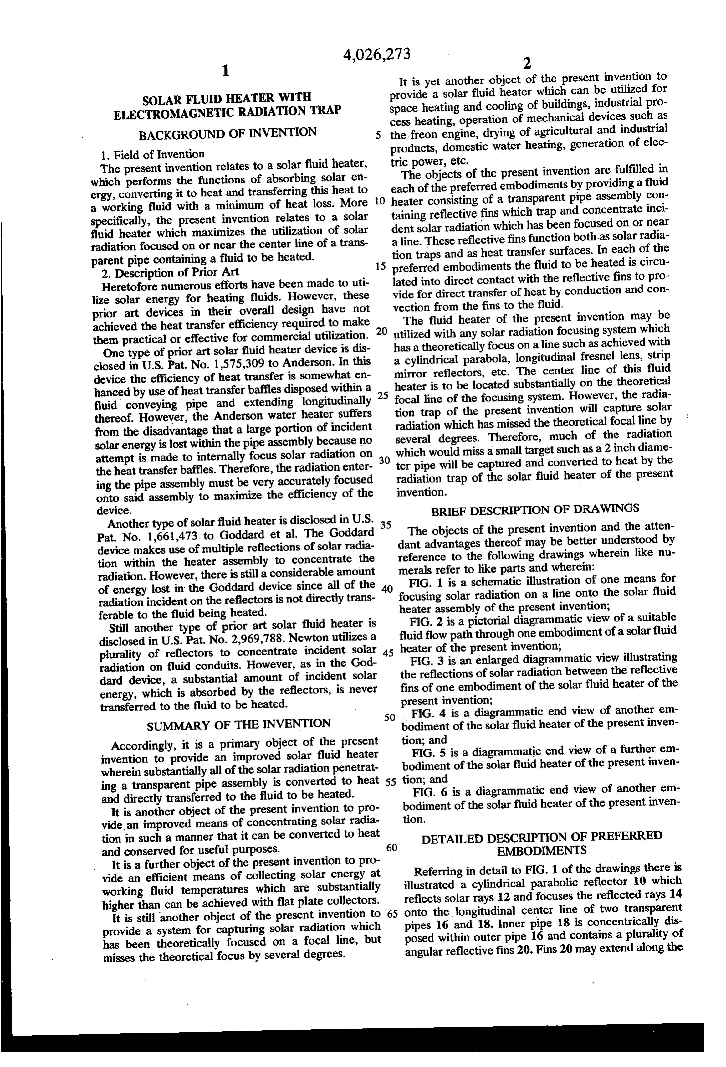
It is yet another object of the present invention to
SOLAR FLUID HEATER WITH provide a solar fluid heater which can be utilized for ELECTROMAGNETIC RADATION TRAP space heating and cooling of buildings, industrial pro cess heating, operation of mechanical devices such as
BACKGROUND OF INVENTION the freon engine, drying of agricultural and industrial 1. Field of Invention products, domestic water heating, generation of elec The present invention relates to a solar fluid heater, tric power, etc.
which performs the functions of absorbing solar en each The objects of the present invention are fulfilled in ergy, converting it to heat and transferring this heat to O heaterofconsisting the preferred embodiments by providing a fluid of a transparent pipe assembly con a working fluid with a minimum of heat loss. More taining reflective fins which trap and concentrate inci specifically, the present invention relates to a solar dent solar radiation which has been focused on or near fluid heater which maximizes the utilization of solar a line. These reflective fins function both as solar radia radiation focused on or near the center line of a trans parent pipe containing a fluid to be heated. tion traps and as heat transfer surfaces. In each of the 15 preferred embodiments the fluid to be heated is circu 2. Description of Prior Art lated into direct contact with the reflective fins to pro Heretofore numerous efforts have been made to uti lize solar energy for heating fluids. However, these vide for direct transfer of heat by conduction and con prior art devices in their overall design have not vection from the fins to the fluid. achieved the heat transfer efficiency required to make 20 utilized with heater
The fluid of the present invention may be any solar radiation focusing system which them practical or effective for commercial utilization. has a theoretically focus on a line such as achieved with One type of prior art solar fluid heater device is dis a cylindrical parabola, longitudinal fresnel lens, strip closed in U.S. Pat. No. 1,575,309 to Anderson. In this device the efficiency of heat transfer is somewhat en mirror reflectors, etc. The center line of this fluid heater is to be located substantially on the theoretical hanced by use of heat transfer baffles disposed within a 25 focal line of the focusing system. However, the radia fluid conveying pipe and extending longitudinally tion trap of the present invention will capture solar thereof. However, the Anderson water heater suffers radiation which from the disadvantage that a large portion of incident several degrees.hasTherefore, missed the theoretical focal line by solar energy is lost within the pipe assembly because no which would miss a small targetmuch of the radiation such as a 2 inch diame attempt is made to internally focus solar radiation on 30 ter pipe will be captured and converted to heat by the the heat transfer baffles. Therefore, the radiation enter radiation trap of the solar fluid heater of the present ing the pipe assembly must be very accurately focused invention.
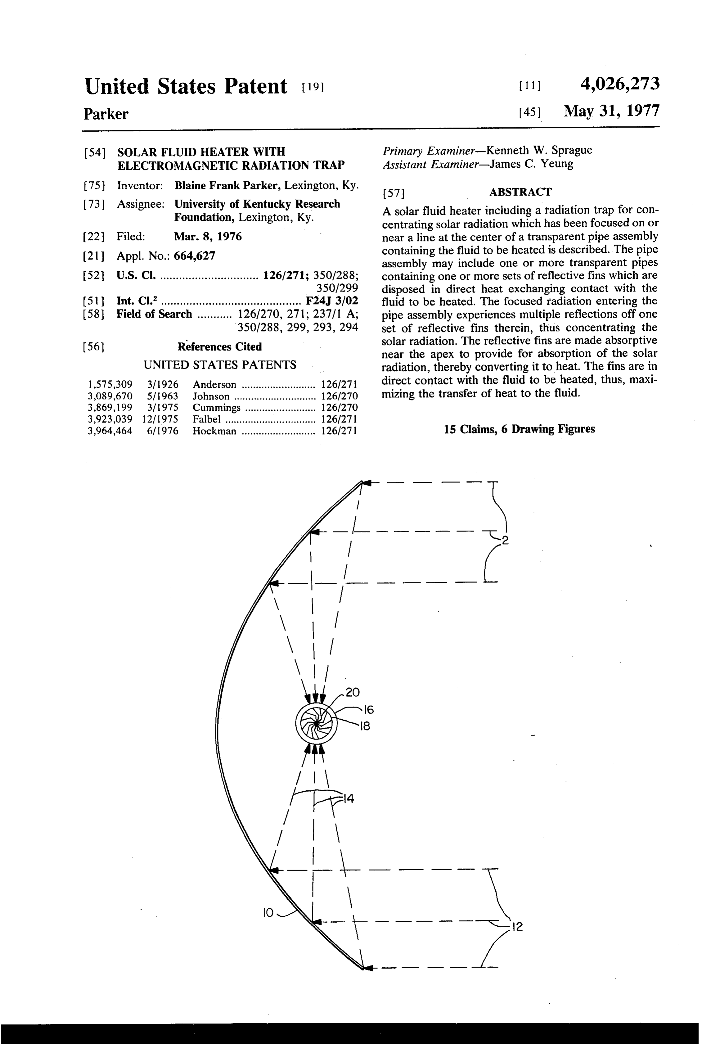
onto said assembly to maximize the efficiency of the device. BRIEF DESCRIPTION OF DRAWINGS Another type of solar fluid heater is disclosed in U.S. 35 The objects of the present invention and the atten Pat. No. 1,661,473 to Goddard et al. The Goddard dant advantages thereof may be better understood by device makes use of multiple reflections of solar radia reference to the following drawings wherein like nu tion within the heater assembly to concentrate the merals refer to like parts and wherein: radiation. However, there is still a considerable amount FIG. 1 is a schematic illustration of one means for of energy lost in the Goddard device since all of the 40 focusing solar radiation on a line onto the solar fluid radiation incident on the reflectors is not directly trans heater assembly of the present invention; ferable to the fluid being heated.
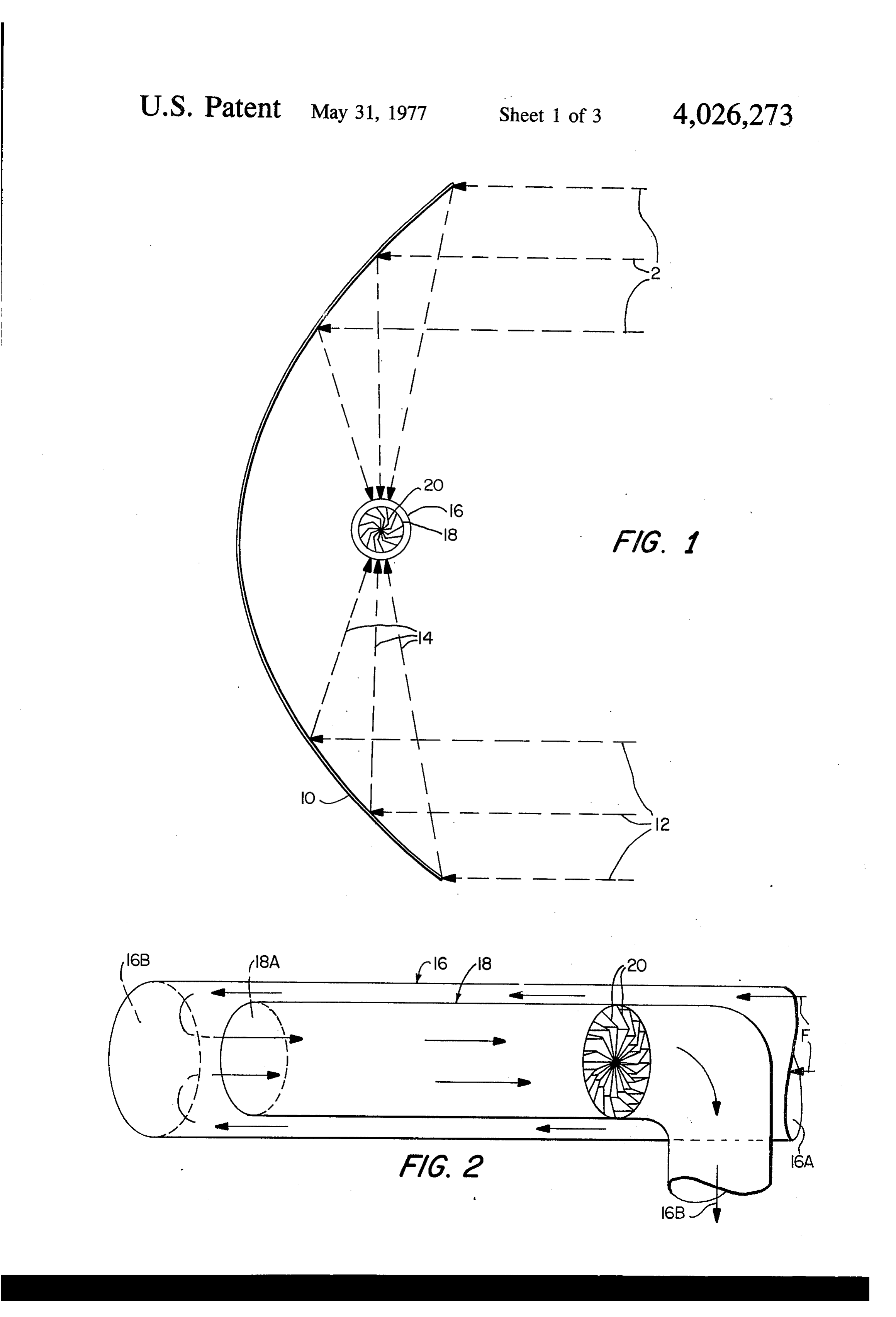
Still another type of prior art solar fluid heater is fluid flow path throughdiagrammatic
FIG. 2 is a pictorial one view of a suitable embodiment of a solar fluid disclosed in U.S. Pat. No. 2,969,788. Newton utilizes a heater of the present invention;
plurality of reflectors to concentrate incident solar 45
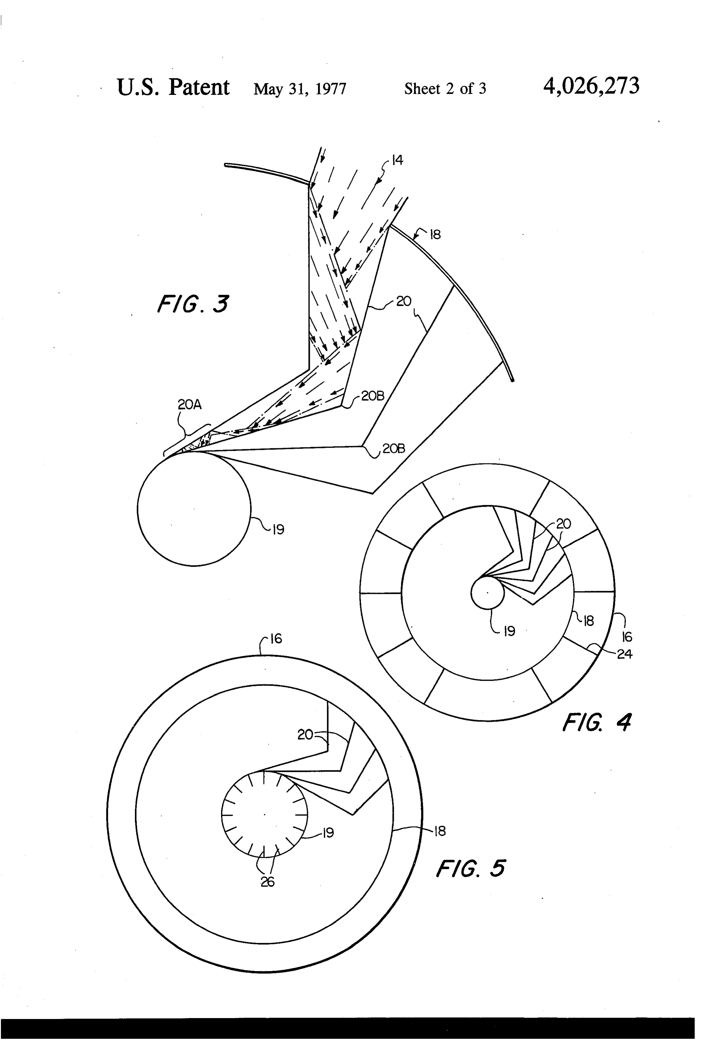
FIG. 3 is an enlarged diagrammatic view illustrating radiation on fluid conduits. However, as in the God the reflections of solar radiation between the reflective dard device, a substantial amount of incident solar fins of one embodiment of the solar fluid heater of the energy, which is absorbed by the reflectors, is never present invention;
transferred to the fluid to be heated.
50 FIG. 4 is a diagrammatic end view of another em sUMMARY OF THE INVENTION bodiment of the solar fluid heater of the present inven Accordingly, it is a primary object of the present tion; and
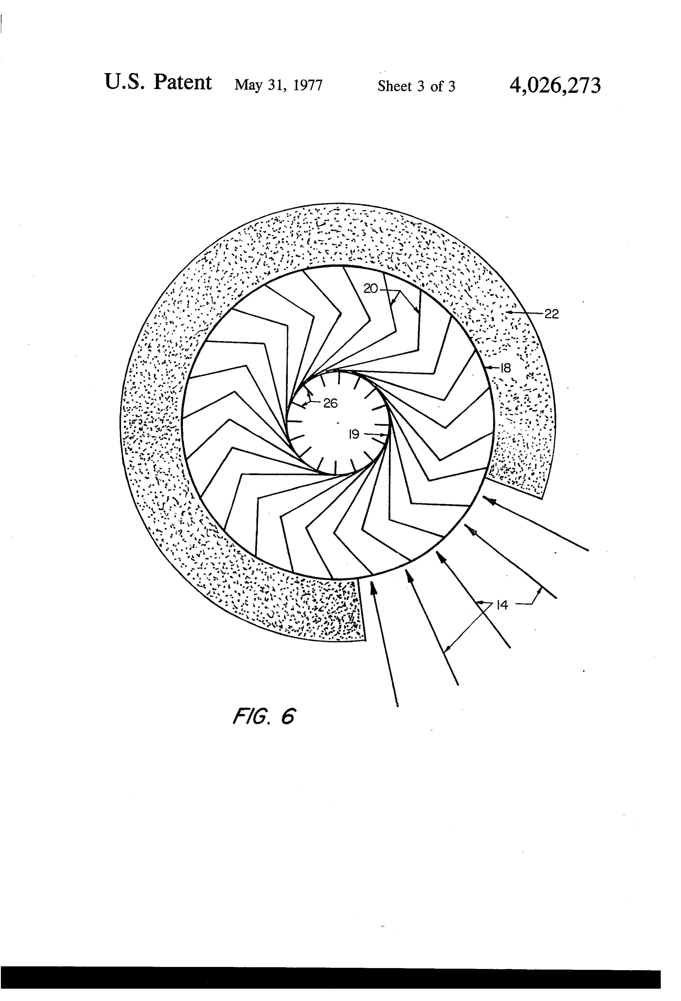
FIG. 5 is a diagrammatic end view of a further em invention to provide an improved solar fluid heater bodiment of the solar fluid heater of the present inven wherein substantially all of the solar radiation penetrat ing a transparent pipe assembly is converted to heat 55 tion; and and directly transferred to the fluid to be heated. FIG. 6 is a diagrammatic end view of another em It is another object of the present invention to pro bodiment of the solar fluid heater of the present inven vide an improved means of concentrating solar radia tion.
tion in such a manner that it can be converted to heat DETAILED DESCRIPTION OF PREFERRED and conserved for useful purposes. 60 EMBODIMENTS
It is a further object of the present invention to pro Referring in detail to FIG. 1 of the drawings there is vide an efficient means of collecting solar energy at illustrated a cylindrical working fluid temperatures which are substantially reflects solar rays 12 andparabolic reflector 10 which higher than can be achieved with flat plate collectors. 65 onto the longitudinal center line of reflected
two transparent
It is still another object of the present invention to pipes 16 and 18. Inner pipe 18 is concentrically provide a system for capturing solar radiation which posed within outer pipe 16 and contains a pluralitydis of has been theoretically focused on a focal line, but angular reflective fins 20. Fins 20 may extend along the misses the theoretical focus by several degrees.
Page 6
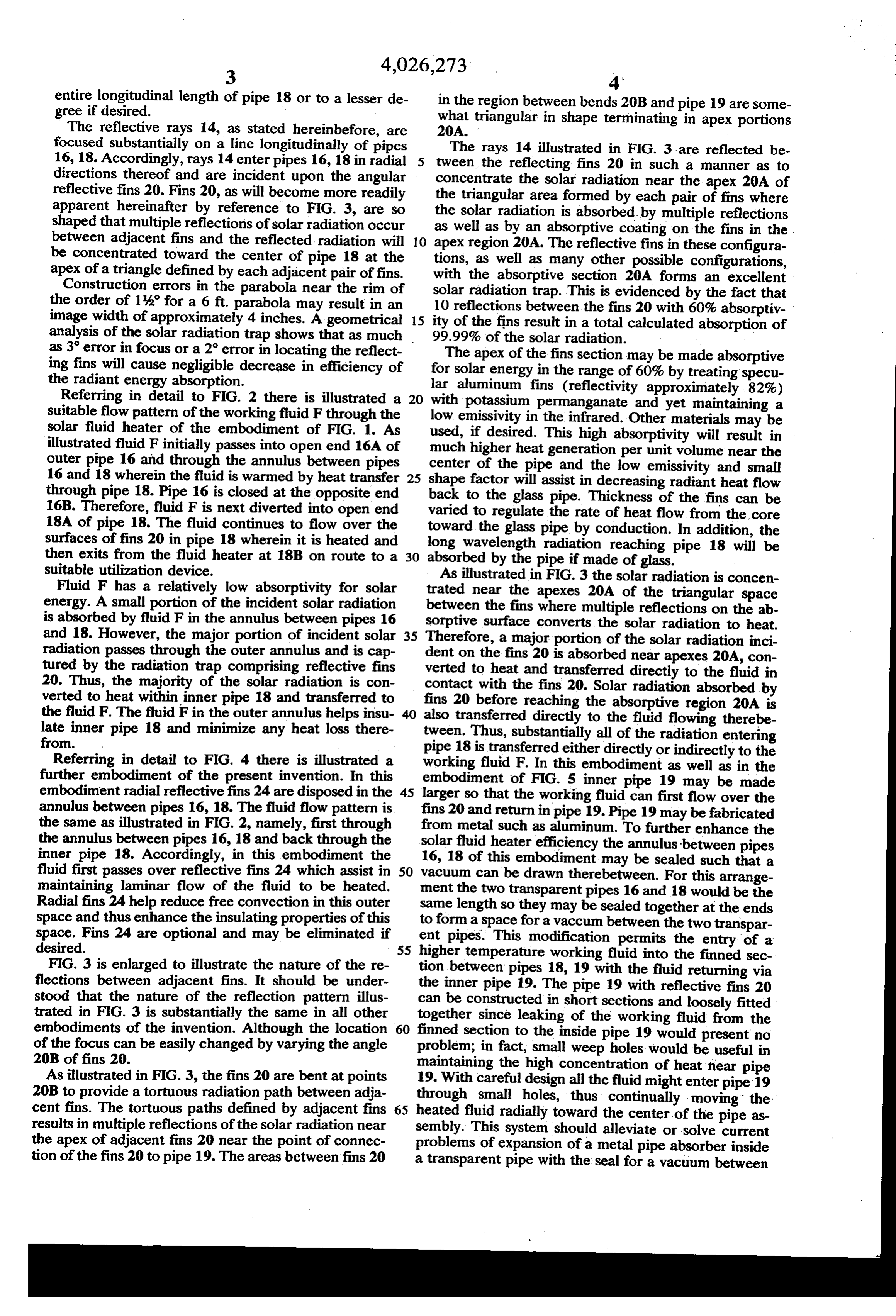
3 4,026,273 4' entire longitudinal length of pipe 18 or to a lesser de in the region between bends 20B and pipe 19 are some gree if desired. what triangular in shape terminating in apex portions The reflective rays 14, as stated hereinbefore, are 20A.
focused substantially on a line longitudinally of pipes The rays 14 illustrated in FIG. 3 are reflected be 16, 18. Accordingly, rays 14 enter pipes 16, 18 in radial 5 tween the reflecting fins 20 in such a manner as to directions thereof and are incident upon the angular concentrate the solar radiation near the apex 20A of reflective fins 20. Fins 20, as will become more readily the triangular area formed by each pair of fins where apparent hereinafter by reference to FIG. 3, are so the solar radiation is absorbed by multiple reflections shaped that multiple reflections of solar radiation occur as well as by an absorptive coating on the fins in the between adjacent fins and the reflected radiation will O apex region 20A. The reflective fins in these configura be concentrated toward the center of pipe 18 at the tions, as well as many other possible configurations, apex of a triangle defined by each adjacent pair offins. with the absorptive section 20A forms an excellent Construction errors in the parabola near the rim of the order of 1% for a 6 ft. parabola may result in an solar 10 radiation trap. This is evidenced by the fact that reflections between the fins 20 with 60% absorptiv image width of approximately 4 inches. A geometrical 15 ity of the fins result analysis of the solar radiation trap shows that as much 99.99% of the solar inradiation. a total calculated absorption of as 3' error in focus or a 2 error in locating the reflect ing fins will cause negligible decrease in efficiency of forThe apex of the fins section may be made absorptive solar energy in the range of 60% by treating specu the radiant energy absorption. lar aluminum fins (reflectivity approximately 82%) Referring in detail to FIG. 2 there is illustrated a 20 with potassium permanganate and yet maintaining a suitable flow pattern of the working fluid F through the low emissivity in the infrared. Other materials may be solar fluid heater of the embodiment of FIG. 1. As illustrated fluid F initially passes into open end 16A of used, if desired. This high absorptivity will result in much higher heat generation per unit volume near the outer pipe 16 and through the annulus between pipes center of the pipe and the low emissivity and small 16 and 18 wherein the fluid is warmed by heat transfer 25 shape factor will assist in decreasing radiant heat flow through pipe 18. Pipe 16 is closed at the opposite end back 16B. Therefore, fluid F is next diverted into open end variedtotothe glass pipe. Thickness of the fins can be regulate the rate of heat flow from the core 18A of pipe 18. The fluid continues to flow over the toward the glass pipe by conduction. In addition, the surfaces of fins 20 in pipe 18 wherein it is heated and long wavelength radiation reaching pipe 18 will be then exits from the fluid heater at 18B on route to a 30 absorbed by the pipe if made of glass. suitable utilization device. As illustrated in FIG. 3 the solar radiation is concen Fluid F has a relatively low absorptivity for solar trated near the apexes 20A of the triangular space energy. A small portion of the incident solar radiation between the fins where multiple reflections on the ab is absorbed by fluid F in the annulus between pipes 16 sorptive surface converts the solar radiation to heat. and 18. However, the major portion of incident solar 35 Therefore, a major portion of the solar radiation inci radiation passes through the outer annulus and is cap tured by the radiation trap comprising reflective fins dent on the fins 20 is absorbed near apexes 20A, con verted to heat and transferred directly to the fluid in 20. Thus, the majority of the solar radiation is con contact with the fins 20. Solar radiation absorbed by verted to heat within inner pipe 18 and transferred to fins 20 before reaching the absorptive region 20A is the fluid F. The fluid F in the outer annulus helps insul 40 also transferred directly to the fluid flowing therebe late from.
inner pipe 18 and minimize any heat loss there tween. Thus, substantially all of the radiation entering pipe 18 is transferred either directly or indirectly to the
Referring in detail to FIG. 4 there is illustrated a working fluid F. In this embodiment as well as in the further embodiment of the present invention. In this embodiment of FIG. 5 inner pipe 19 may be made embodiment radial reflective fins 24 are disposed in the 45 larger so that the working fluid can first flow over the annulus between pipes 16, 18. The fluid flow pattern is fins 20 and return in pipe 19. Pipe 19 may be fabricated the same as illustrated in FIG. 2, namely, first through from metal such as aluminum. To further enhance the the annulus between pipes 16, 18 and back through the solar fluid heater efficiency the annulus between pipes inner pipe 18. Accordingly, in this embodiment the 16, 18 of this embodiment may be sealed such that a fluid first passes over reflective fins 24 which assist in 50 vacuum can be drawn therebetween. For this arrange maintaining laminar flow of the fluid to be heated. ment the two transparent pipes 16 and 18 would be the Radial fins 24 help reduce free convection in this outer same length so they may be sealed together at the ends space and thus enhance the insulating properties of this to form a space for a vaccum between the two transpar space.
desired.
Fins 24 are optional and may be eliminated if ent pipes. This modification permits the entry of a 55 higher temperature working fluid into the finned sec
FIG. 3 is enlarged to illustrate the nature of the re tion between pipes 18, 19 with the fluid returning via flections between adjacent fins. It should be under the inner pipe 19. The pipe 19 with reflective fins 20 stood that the nature of the reflection pattern illus can be constructed in short sections and loosely fitted trated in FIG. 3 is substantially the same in all other together since leaking of the working fluid from the embodiments of the invention. Although the location 60 of the focus can be easily changed by varying the angle finned section to the inside pipe 19 would present no problem; in fact, small weep holes would be useful in 20B offins 20. maintaining the high concentration of heat near pipe As illustrated in FIG. 3, the fins 20 are bent at points 19. With careful design all the fluid might enter pipe 19 20B to provide a tortuous radiation path between adja through small holes, thus continually moving the cent fins. The tortuous paths defined by adjacent fins 65 heated fluid radially toward the center of the pipe as results in multiple reflections of the solar radiation near sembly. This system should alleviate or solve current the apex of adjacent fins 20 near the point of connec problems of expansion of a metal pipe absorber inside tion of the fins 20 to pipe 19. The areas between fins 20 a transparent pipe with the seal for a vacuum between
Page 7
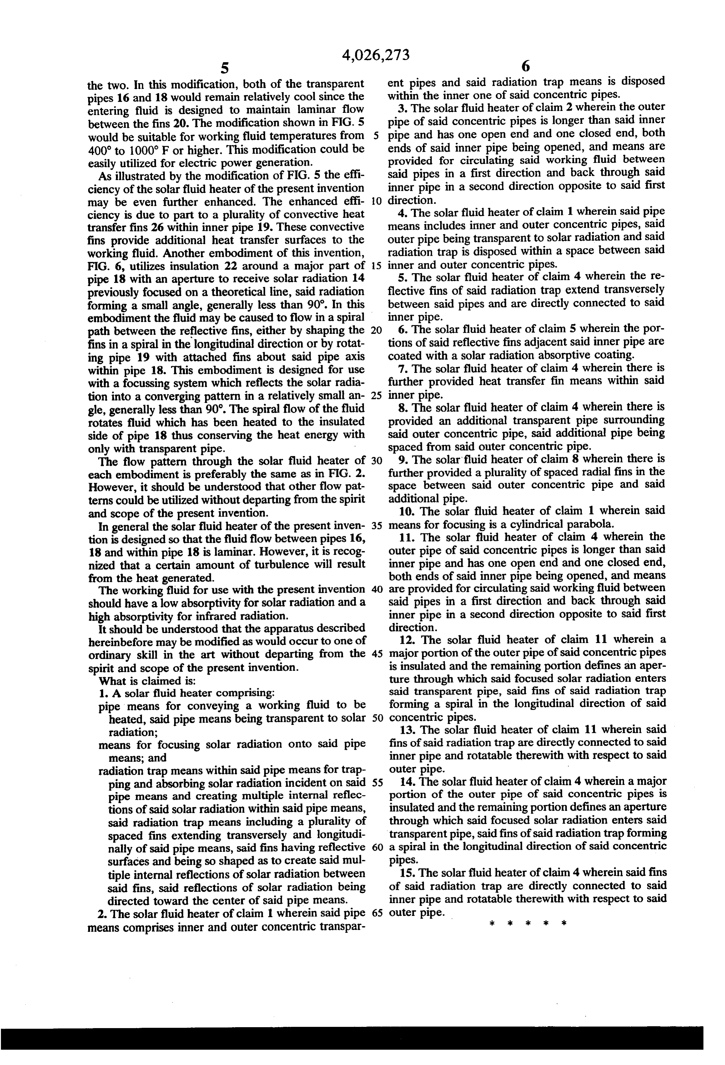
the two. In this modification, both of the transparent ent pipes and said radiation trap means is disposed pipes 16 and 18 would remain relatively cool since the within the inner one of said concentric pipes. 3. The solar fluid heater of claim 2 wherein the outer entering fluid is designed to maintain laminar flow between the fins 20. The modification shown in FIG. 5 pipe of said concentric pipes is longer than said inner would be suitable for working fluid temperatures from 5 pipe and has one open end and one closed end, both ends of said inner pipe being opened, and means are 400 to 1000 F or higher. This modification could be provided easily utilized for electric power generation. for circulating said working fluid between As illustrated by the modification of FIG. 5 the effi said pipes in a first direction and back through said ciency of the solar fluid heater of the present invention inner pipe in a second direction opposite to said first may be even further enhanced. The enhanced effi O direction.
ciency is due to part to a plurality of convective heat 4. The solar fluid heater of claim 1 wherein said pipe transfer fins 26 within inner pipe 19. These convective means includes inner and outer concentric pipes, said fins provide additional heat transfer surfaces to the outer pipe being transparent to solar radiation and said working fluid. Another embodiment of this invention, radiation trap is disposed within a space between said FIG. 6, utilizes insulation 22 around a major part of 15 inner and outer concentric pipes. pipe 18 with an aperture to receive solar radiation 14 5. The solar fluid heater of claim 4 wherein the re previously focused on a theoretical line, said radiation flective fins of said radiation trap extend transversely forming a small angle, generally less than 90'. In this between said pipes and are directly connected to said embodiment the fluid may be caused to flow in a spiral inner pipe.
path between the reflective fins, either by shaping the 20 6. The solar fluid heater of claim 5 wherein the por fins in a spiral in the longitudinal direction or by rotat tions of said reflective fins adjacent said inner pipe are ing pipe 19 with attached fins about said pipe axis coated with a solar radiation absorptive coating. within pipe 18. This embodiment is designed for use 7. The solar fluid heater of claim 4 wherein there is with a focussing system which reflects the solar radia further provided heat transfer fin means within said tion into a converging pattern in a relatively small an 25 inner pipe.
gle, generally less than 90°. The spiral flow of the fluid 8. The solar fluid heater of claim 4 wherein there is rotates fluid which has been heated to the insulated provided an additional transparent pipe surrounding side of pipe 18 thus conserving the heat energy with said outer concentric pipe, said additional pipe being only with transparent pipe. spaced from said outer concentric pipe. The flow pattern through the solar fluid heater of 30 9. The solar fluid heater of claim 8 wherein there is each embodiment is preferably the same as in FIG. 2. further provided a plurality of spaced radial fins in the However, it should be understood that other flow pat space between said outer concentric pipe and said terms could be utilized without departing from the spirit additional pipe.
and scope of the present invention. 10. The solar fluid heater of claim 1 wherein said In general the solar fluid heater of the present inven 35 means for focusing is a cylindrical parabola. tion is designed so that the fluid flow between pipes 16, 11. The solar fluid heater of claim 4 wherein the 18 and within pipe 18 is laminar. However, it is recog outer pipe of said concentric pipes is longer than said nized that a certain amount of turbulence will result inner pipe and has one open end and one closed end, from the heat generated. both ends of said inner pipe being opened, and means The working fluid for use with the present invention 40 are provided for circulating said working fluid between should have a low absorptivity for solar radiation and a said pipes in a first direction and back through said high absorptivity for infrared radiation. inner pipe in a second direction opposite to said first It should be understood that the apparatus described direction.
hereinbefore may be modified as would occur to one of 12. The solar fluid heater of claim 11 wherein a ordinary skill in the art without departing from the 45 majorportion of the outer pipe of said concentric pipes spirit and scope of the present invention. is insulated and the remaining portion defines an aper What is claimed is: ture through which said focused solar radiation enters 1. A solar fluid heater comprising: said transparent pipe, said fins of said radiation trap pipe means for conveying a working fluid to be forming a spiral in the longitudinal direction of said heated, said pipe means being transparent to solar 50 concentric pipes.
radiation; 13. The solar fluid heater of claim 11 wherein said means for focusing solar radiation onto said pipe fins of said radiation trap are directly connected to said means; and inner pipe and rotatable therewith with respect to said radiation trap means within said pipe means for trap outer pipe.
ping and absorbing solar radiation incident on said 55 14. The solar fluid heater of claim 4 wherein a major pipe means and creating multiple internal reflec portion of the outer pipe of said concentric pipes is tions of said solar radiation within said pipe means, insulated and the remaining portion defines an aperture said radiation trap means including a plurality of through which said focused solar radiation enters said spaced fins extending transversely and longitudi transparent pipe, said fins of said radiation trap forming nally of said pipe means, said fins having reflective 60 a spiral in the longitudinal direction of said concentric surfaces and being so shaped as to create said mul pipes.
tiple internal reflections of solar radiation between 15. The solar fluid heater of claim 4 wherein said fins said fins, said reflections of solar radiation being of said radiation trap are directly connected to said directed toward the center of said pipe means. inner pipe and rotatable therewith with respect to said 2. The solar fluid heater of claim 1 wherein said pipe 65 outer pipe. sk x k is sk means comprises inner and outer concentric transpar
Provenance
- Collection
- Cited prior art
- Original PDF
- patentimages.storage.googleapis.com →
- Filed
- 1976-03-08
- Pages
- 7
- Method
- pdftotext (the PDF's own text layer) + pdftoppm 300dpi page scans
- Source
- Google Patents bibliographic record
- Granted
- 1977-05-31
- Inventors
- Blaine Frank Parker; University of Kentucky Research Foundation
- Transcribed from
- patentimages.storage.googleapis.com →