patent · US3781162
Reducing nox formation by combustion
25 December 1973
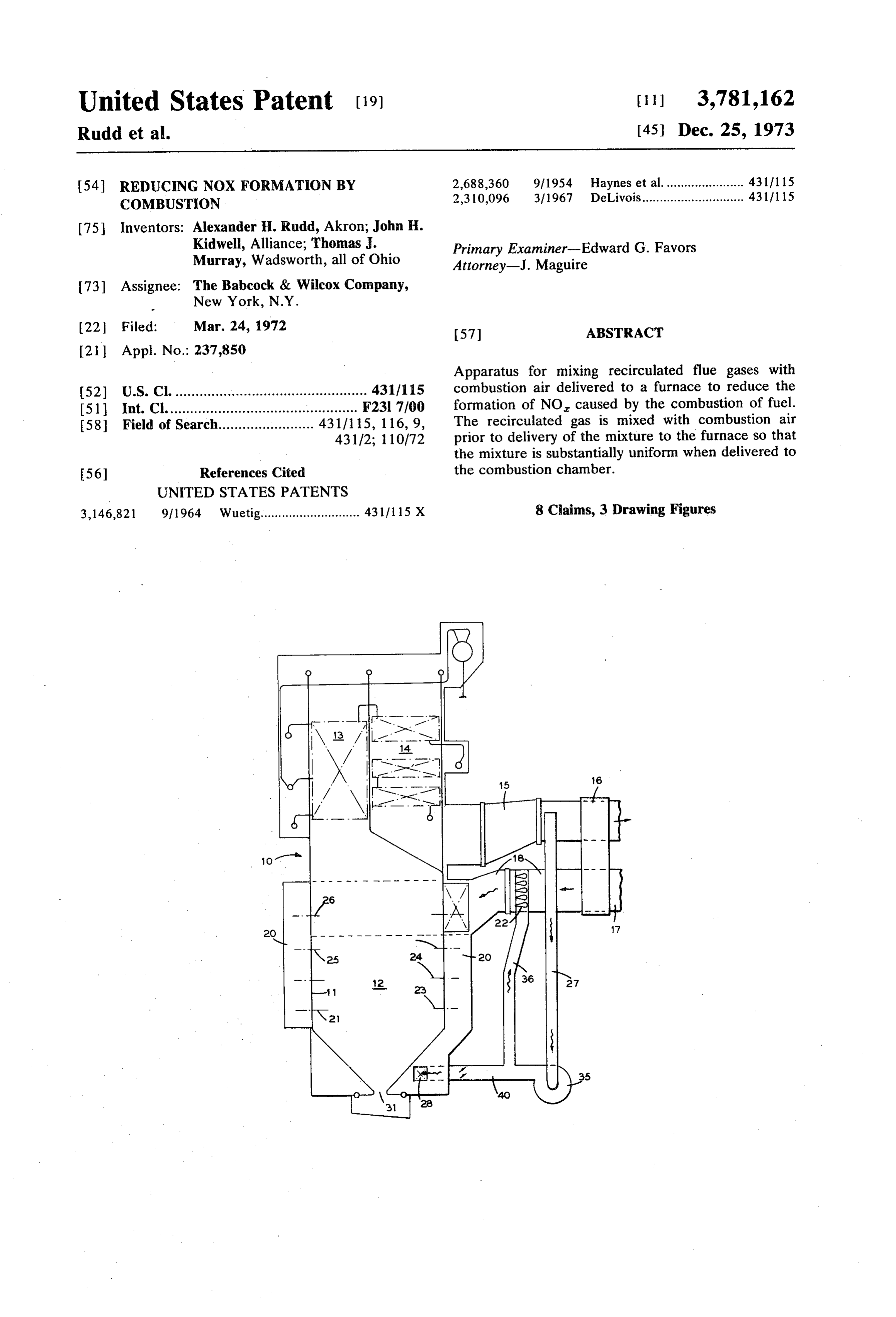
Page 1 — bibliographic record
United States Patent 19 (11) 3,781,162 Rudd et al. (45) Dec. 25, 1973 54 REDUCING NOX FORMATION BY 2,688,360 9, 1954 Haynes et al....................... 431/1 15 COMBUSTION 2,310,096 3/1967 DeLivois............................. 4311 115 75 Inventors: Alexander H. Rudd, Akron; John H.
Kidwell, Alliance; Thomas. Primary Examiner-Edward G. Favors
Murray, Wadsworth, all of Ohio Attorney-J. Maguire 73 Assignee: The Babcock & Wilcox Company,
New York, N.Y.
22 Filed: Mar. 24, 1972 57 ABSTRACT
Apparatus for mixing recirculated flue gases with 52 U.S. Cl. ................................................ 431/115 combustion air delivered to a furnace to reduce the 51 int. Cl................................................ F231 7700 formation of NO caused by the combustion of fuel. 58) Field of Search........................ 431/15, 116, 9, The recirculated gas is mixed with combustion air 431/2; 110/72 prior to delivery of the mixture to the furnace so that the mixture is substantially uniform when delivered to 56 References Cited the combustion chamber.
UNITED STATES PATENTS
3,146,821 9/1964 Wuetig............................ 431/1 15 X 8 Claims, 3 Drawing Figures
Page 2
Drawing sheet — no readable text.
Page 3
Drawing sheet — no readable text.
Page 4
REDUCING NOX FORMATION BY COMBUSTON point of fuel introduction into the boiler combustion chamber. In the usual boiler unit some device is pro
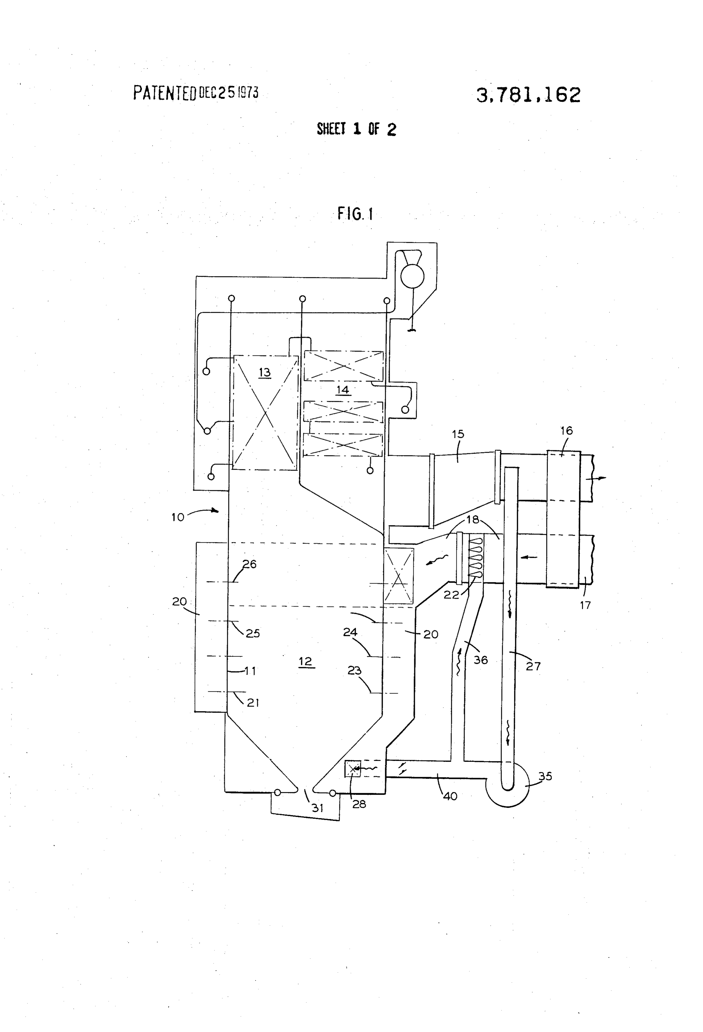
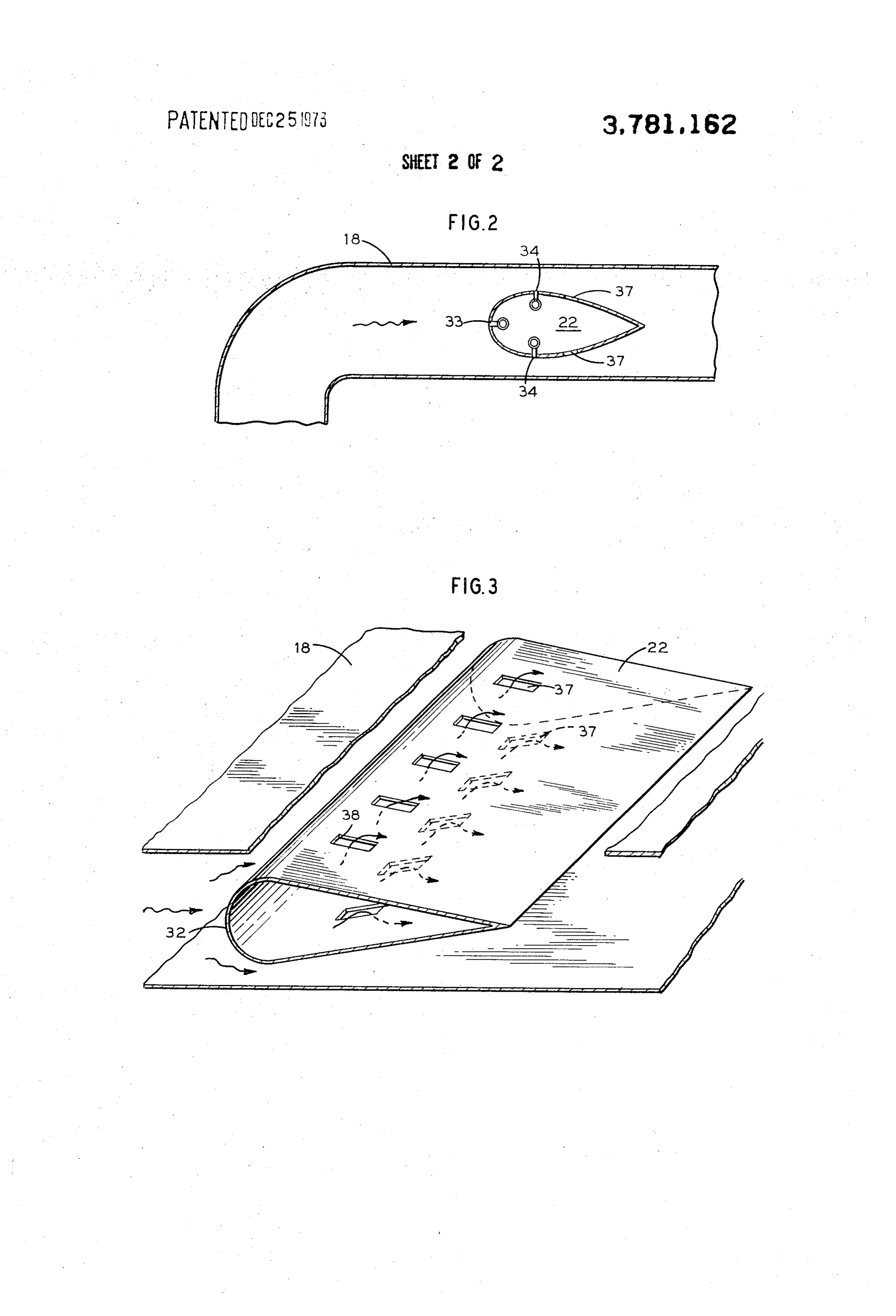
The present invention relates to apparatus for burn vided to measure the combustion air flow to the com ing fuel with a reduction in the quantity of nitrogen ox bustion chamber and in many installations the device ides formed during the combustion of the fuel. Particu 5 may take the form of a restriction in the air supply duct larly the invention relates to a system for controlling such as a venturi or a venture-like tube, or one or more the combustion of the fuel so as to minimize the forma air foils. Advantageously in the present invention the tion of nitrogen oxides during combustion. recirculated gases, for NO reduction purposes, is Nitric oxide (NO) and nitrogen dioxide (NO) are added downstream of the air flow restriction (in an air often contained in the exhaust gases from combustion 10 flow sense) to minimize the pressure and thus the processes. Their presence is due to formation of NO power required by the recirculated gas fan, and to in during combustion and subsequent oxidation of a small sure intimate mixing of the recirculated gases with the part of the NO to NO, by residual oxidation in the combustion air. Of the drawings: FIG. 1 is a schematic elevation of a conventional products of combustion passing through a furnace chamber. After release to the atmosphere, oxidation of 15 power boiler incorporating the present invention; NO continues, and the resulting NO, is an air pollutant. FIG. 2 is an enlarged view, in section, of a portion of Nitrogen dioxide is best known for its participation in the apparatus shown in FIG. 1; an smog formation, but also exhibits some deleterious ef FIG. 3 is an isometric view, partly in section, of the fects of its own. Since NO is, from an air pollution point 20 apparatus shown in FIG. 2.
of view, synonymous with NO, the two are often com In the illustrated embodiment of the invention de bined and referred to as NO. picted in FIG. 1 a conventional power generation boiler Not all combustion processes operate at sufficiently is shown. In the particular arrangement the furnace and high temperature to produce significant quantities of boiler setting 10 includes steam generating tubes 11 so NO. The major producers are the automobile, and in 25 arranged that a combustion chamber 12 is positioned dustrial and utility boilers. Reduction of NO emissions in the lower portion of the setting. The gases of com from utility boilers on the West Coast in the late 1950's bustion produced in the combustion chamber pass up is one of the earliest examples of air pollution control. wardly over vapor heating surfaces 13, turn and then This was achieved primarily by a modification of the pass downwardly over additional heat exchange sur combustion process known as two-stage combustion as faces 14 before discharge through a connecting duct 15 disclosed in U.S. Pat No. 3,048,131. More recently 30 to a conventional air heater 16. The heat exchange sur NO pollution has been shown to be a general nuisance faces may include superheater elements, reheater ele in many parts of the country, and work has begun in ments, and economizer surfaces. The surfaces are in both the automobile industry and continued in the tended to heat the fluids passing therethrough and to boiler industry to reduce NO, emmissions to the atmo 35 reduce the temperature of the flue gas discharging from sphere. the setting 10 through the duct 15 to the air heater 16. The amount of NO formation in a boiler furnace is The air heater illustrated is of the regenerative type determined by the temperature and composition his where relatively low level heat from the flue gas is tory of the combustion gas during and after combus transferred to combustion air entering through a duct tion. This is related in turn to fuel supply conditions 40 17 which is thereafter passed through a duct 18 to a and other operating and design factors of the boiler. windbox 20 and burner ports 21 serving the chamber Some of the primary factors found to be of importance 12. Ordinarily, in units of the type described the com to NO production relate to the rate of fuel supply and bustion air flow to the burner ports 21 is regulated to the values of oxygen available during and immediately be in proper flow relationship to the fuel also being sup after combustion of the fuel (i.e., excess air used in the 45 plied through burners positioned in the ports 21 and combustion process), the configuration and rate of thus to the combustion chamber 12. To this end, in cooling in the combustion chamber, and the tempera in many installations streamlined air foils 22 are installed ture of the combustion air delivered to the furnace and the air duct 18 so as to measure the flow of air there combined with the fuel during the combustion process. through and to provide a measurement for use in the All of such factors affect the generation of NO, during 50 fuel-air control of the unit. The air foils illustrated in fuel combustion by directly or indirectly influencing FIG. 1 are shown in greater detail in FIGS. 2 and 3 and temperatures in the combustion chamber. will be more completely described hereinafter. Heretofore, reduction of NO production in existing In the arrangement shown in FIG. 1, the burner ports large industrial and utility boiler units has been at 21 are arranged to utilize either oil or gas fuel. The tempted by the injection of recirculated flue gases into 55 burners, as illustrated, are each located in a burner port the combustion chamber. This has not always been suc with the ports positioned in opposite walls of the com cessful, since it is important the recirculated flue gas be bustion chamber 12 and arranged in vertically spaced well mixed with the combustion air so that each of the rows 23, 24 and 25 with the ports and the burners hori multiple burners in such an installation receives its pro zontally spaced in each row. In the arrangement illus portionate share of oxygen for fuel combustion pur 60 trated each row 23 and 24 of burners and burner ports . in the lowermost portion of the chamber 12 contain 4 poses. The burner or burners getting the least oxygen horizontally (because of faulty mixing or gas distribution) would ei spaced burners while the uppermost row ther smoke or have unstable and incomplete combus 25 contains 2 burners. It will be appreciated that tion of the fuel thereby limiting the amount of gas recir greater or lesser numbers of ports and burners may be culation and the degree of NO reduction. 65 utilized, and any fuel could be used. According to the present invention it has been found 26Inisthe installation illustrated in FIG. 1, a row of ports positioned above the uppermost row 25 of burn that recirculated gases can be intimately and thor oughly mixed with combustion air upstream of the ers. Specifically, in the embodiment shown, there are
Page 5
4 ports in each row 26 and the spacing in a vertical di Referring to FIGS. 2 and 3 it will be noted the airfoils rection between the uppermost row 25 of the burner 22 as ordinarily installed for air flow measurement pur ports and the ports 26 is equal to or greater than the poses are positioned in the duct 18 in single or multiple vertical spacing between the rows 23, 24 and 25 of fuel layers, depending upon the volume of air flow, with the burner ports. 5 large end 32 of the air foil facing upstream insofar as In the embodiment shown, gas recirculation is uti air flow direction is concerned. In the usual air flow lized for vapor temperature control purposes. Such measurement procedure, a pressure measurement is gases may be introduced into the furnace at any of vari obtained by positioning a tap 33 on the upstream facing ous positions. As shown, gases are withdrawn from the edge of the air foil. One or more taps 34 are positioned duct 15 and passed through connecting ducts 27, 10 at right angles to the air flow direction adjacent the through fan 35 and duct 40, to gas plenum chambers thickest portion of the airfoil. The differential pressure 28 formed beneath the inclined tubes 30 defining the measurements between the taps 33 and 34 will be in bottom of the chamber, and which receive the recircu dicative of the rate of air flow through the duct 18. This lated gas and pass this gas upwardly through an opening differential pressure measurement when properly cali 31 in the bottom of the furnace to mix with the prod 15 brated can be utilized to measure the rate of air flow ucts of combustion in passing over the heat exchange through the duct, and has also been utilized in air flow surfaces 13 and 14 in the upper portion of the setting steam flow control arrangements to coordinate air and 10. As is well known in the art, recirculated flue gases fuel delivery to the combustion chamber 12. when used for vapor temperature control purposed in Recirculated gas is passed from the duct 27 through crease with the decrease in the rate of fuel firing. The 20 a recirculated gas fan 35 and a dampered branch duct intent of this type of operation is to regulate gas mass 36 with the recirculated gases delivered to the interior flow over the heat exchange surfaces 13 and 14. This of the air foils 22. Ordinarily, such gases are delivered regulates heat exchange to the vapor heating surfaces to both ends of the hollow airfoil particularly when the during low load operations. length of the air foil is substantial, as is usually encoun It has recently been found that the addition of recir 25 tered in a large capacity boiler unit. culated gases with the combustion air admitted to the As shown particularly in FIG. 3, and in accordance burners with the fuel aids in reducing the nitrogen with the present invention, openings 37 are provided in oxide produced during the combustion process. One of the air foil to interconnect the interior of the air foil the difficulties heretofore encountered has been re with the flow path of the combustion air stream along lated to a proper mixing of the recirculated gases with 30 the exterior surface of the foil. These openings are the combustion air as the two gases are injected into spaced along the longitudinal length of the air foil at the combustion chamber. Ordinarily, the use of recir positions down stream of the maximum thickness of the culated gases to the furnace chamber for nitrogen airfoil shape. With the openings so positioned the aspi oxide control purposes has required a maximum flow ration effect of combustion air flow over the foils will of such gases to the furnace during periods of maxi 35 tend to draw recirculated gas from the hollow foils into mum fuel combustion. That is, of course, the reverse of the stream of air passing through the air duct 18. Due the normal use of recirculated gases for vapor tempera to such flow it has been found that the recirculated ture control purposes. gases intimately mix with the combustion air so that a In accordance with the present invention, the recir 40 nearly equally mixed combination of the two gases may culated gases removed from the flue gas duct 15 are be delivered to the wind box 20 and through each of mixed with the combustion air before the mixed gases the ports 23, 24 and 25 with the fuel to the combustion are delivered to the windboxes 20 of the furnace set chamber 12.
ting. In the usual installation the air flow duct through In the arrangement shown in FIG. 1, the concept of which combustion air is supplied to the windbox and 45 U.S. Pat. No. 3,048,131 may also be used with the pres thereafter into the furnace is provided with some de ent invention by passing a controlled portion of the vice for measuring the flow of air through the duct. mixture of combustion air and recirculated flue gases This device commonly is a restriction, such as an ori through the ports 26. Under such circumstances fuel fice of the plate type, one or more venturis or venturi will not usually be introduced through the ports 26 with like tubes, or in many installations one or more airfoils 50 the mixture of air and gas. Such a combination will arranged in parallel to permit air flow measurements by have a further effect in reducing the formation of NO differential pressures. The restrictive devices are se by fuel combustion.
lected to minimize loss of pressure in the air flowing through the duct for fan power economy while also Good mixing of recirculated flue gas from the inter providing sufficient differential pressure values for ade 55 ior of each foil into the combustion air passing over the quate flow measurement. With such restrictions in the exterior of the foil can be accomplished by forming the openings 37 as slots having a length four to six times the air flow duct we have found that the recirculated flue gases used for NO control purposes can advanta width and having an inter port spacing of from three to geously be admitted to the air stream downstream of eight times the width of each slot. In addition, the up the restrictor for air and gas mixing purposes while 60 'stream edge 38 of the slot should be at least 15° of the minimizing fan pressure and power requirements in the widest part of the foil. Under these conditions it has recirculated flue gas duct opening into the air flow been found the mixing of air and gas is substantially complete.
duct.
In the embodiment shown the air foils 22 are utilized In operation of a combustion unit of the type shown for mixing purposes to ensure a substantially uniform 65 in FIG. 1, when firing oil or gas the amount of gas recir and adequate mingling of combustion air and recircu culated through the foils should be in the range of 10 lated gases before they enter the combustion chamber to 22percent of the combustion air required for fuel 12. combustion to maintain NO production at low values.
Page 6
S 6
We claim: position downstream, in an air flow sense, of the flow 1. Apparatus for reducing the production of NOx by restrictor.
fuel combustion which comprises walls defining a com 3. Apparatus according to claim 2 wherein said air bustion chamber, means defining a plurality of burner flow restrictor consists of at least one foil extending ports in a wall of the combustion chamber, burner across the duct.
means positioned to inject fuel into the combustion 4. Apparatus according to claim 3 wherein the foil is chamber through each of the burner ports, a windbox hollow and the recirculated flue gas duct opens into the enclosing the burner ports for the delivery of combus hollow foil with a transversely spaced series of gas dis tion air through the burner ports with the fuel injected charge openings positioned to discharge through the therethrough for combustion of fuel in the combustion O foil into the air stream passing over the foil downstream chamber, air flow duct means connecting the windbox of the maximum transverse dimension of the foil. with a source of preheated combusted air, means in 5. Apparatus according to claim 4 wherein the recir cluding a restrictor for measuring and dampers and a culated gas duct opens into the opposite ends of said fan for regulating the flow of combustion air through foil.
the duct means to the windbox in coordinated response 15 6. Apparatus according to claim 2 wherein the air to the rate of fuel flow through the ports, flue gas duct flow restrictor consists of a venturi-like tube. means interconnecting the gas discharge end of the 7. Apparatus according to claim 6 wherein the recir combustion chamber with the airflow duct means adja culated flue gas opens into the air stream passing cent the restrictor, said flue gas duct means including through the venturi-like tube around and downstream dampers and a recirculated gas fan for passing recircu in an air flow sense of the minimum cross-sectional lated flue gas to the air flow duct for mixing flue gas area of the venturi-like tube.
with the preheated combustion air and delivered the 8. Apparatus according to claim wherein ports are mixture gases through siad burner ports to reduce the provided in said wall spaced from the burner ports and percentage of oxygen present in the gas mass delivered within the windbox for the controlled introduction of to the combustion chamber and to thereby reduce the 25 mixed combustion air and recirculated gases only into formation of NO by fuel combustion. combustion chamber.
2. Apparatus according to claim wherein the recir culated flue gas duct opens into said air flow duct at a
Provenance
- Collection
- Cited prior art
- Original PDF
- patentimages.storage.googleapis.com →
- Filed
- 1972-03-24
- Pages
- 6
- Method
- pdftotext (the PDF's own text layer) + pdftoppm 300dpi page scans
- Source
- Google Patents bibliographic record
- Granted
- 1973-12-25
- Inventors
- T Murray; A Rudd; J Kidwell; Babcock and Wilcox Co
- Transcribed from
- patentimages.storage.googleapis.com →