patent · US3995421
Method of increasing the output of hydrogen combustion type internal combustion engine by recovery of generated heat and apparatus therefor
7 December 1976
Page 1 — bibliographic record
United States Patent to 3,995,421 Kuroiwa 45 Dec. 7, 1976 54) METHOD OF INCREASING THE OUTPUT 2,447,696 8/1948 Forsyth ......................... 60/39.54 X OF HYDROGEN COMBUSTION TYPE 3, 101592 8/1963 Robertson et al. .............. 60/649 X INTERNAL COMBUSTION ENGINE BY 3,471,274 10/1969 Quigley, Jr. ....................... 123/1 A RECOVERY OF GENERATED HEAT AND 3,608,529 9/1971 Smith et al. ....................... 1231 A
APPARATUS THEREFOR
76 Inventor: Sajio Kuroiwa, 24-15, Nishikuma, Primary Examiner-Allen M. Ostrager Kochi, Kochi, Japan Attorney, Agent, or Firm-Wenderoth, Lind & Ponack
(21) Appl. No.: 527,425 (57) ABSTRACT (30) Foreign Application Priority Data This invention relates to a new method of increasing the output of a hydrogen combustion type internal
Nov. 30, 1973 Japan ............................ 48-3578 combustion engine by recovery of generated heat and 52 U.S. Cl. ......................... 60/39.46 R; 60/39.54; to an apparatus therefor. It is the main object of the 60/39.55; 60/39.69; 123/8.13; 123/8.49 invention to raise engine output by producing steam by (51 Int. Cl.’....................... F02C 7/00; F02C 3/24 having generated heat absorbed in water obtained from 58 Field of Search ............ 60/649, 673, 651, 650, combustion of hydrogen, obtaining high-pressure gen 60/671, 670, 39.46 R, 39.55, 39.54, 39.69; erated steam by having said heat re-absorbed in newly 123/1 A, 8.09, 8.13, 8.49, 78 R, 78 B introduced water and combining said high-pressure
steam with said produced steam.
UNITED STATES PATENTS
2,393,749 ll 1946 Cadella ................................ 123,178 9 Claims, 5 Drawing Figures
Page 2
Drawing sheet — no readable text.
Page 3
Drawing sheet — no readable text.
Page 4
Drawing sheet — no readable text.
Page 5
gine. AS compared with a conventional internal com
METHOD OF INCREASING THE OUTPUT OF bustion engine, which most of such generated heat is HYDRO GEN COMBUSTION TYPE INTERNAL simply disapated into the air without being used, the COMBUSTON ENGINE BY RECOVERY OF method of this invention makes it possible to effectively GENERATED HEAT AND APPARATUS THEREFOR utilize this energy by introducing water or steam into BACKGROUND OF THE INVENTION engine so as to absorb it. Therefore, the thermal effi ciency of the internal combustion engine is improved
It is an incontrovertible fact that the petroleum re and the energy loss greatly reduced. This internal com bustion engine is completely free from the production
Sources existing on the earth are limited and destined to be exhausted some day. Today the petroleum demand O of harmful matter and is completely non-polluting. is rapidly increasing. If petroleum continues to be con As already stated, hydrogen as an energy source is Sumed at the present high rate, the demand-supply turned into water, if burnt, and the water can be re relation must certainly become unbalanced in the near used for producing hydrogen by decomposition or dis future. As petroleum is unevenly distributed among the sociation. This natural circulation permits an effective countries of the world, “have-not nations cannot 15 exploitation of the limited resources on the earth. avoid facing energy crises as long as they depend upon For a country having limited energy resources, devel petroleum. In recent years, the tendency to regard opment of hydrogen energy systems is the only way to petroleum as almighty has come to be reviewed be success in securing energy. In this sense, putting to cause of its unfavorable effects on the human body. practical use a hydrogen engine as achieved by the With respect to automobiles in particular, there has 20 present invention is of great significance. been a strong cry for pollution-free gasoline engines. The steam generating method to be employed in this This has led to realization of the necessity of the con internal combustion engine is entirely novel. The pre version of engines to a substitute for petroleum as a fuel asent invention is characterized by burning hydrogen in cylinder and utilizing the heat produced from the and of the effective utilization of hydrogen energy in combustion and the heat generated from friction be particular. Hydrogen can be obtained easily at any 25 place on the earth from mere decomposition of water. tween the moving parts of the engine and having such heat absorbed in water injected under pressure or
Therefore, hydrogen resources are practically limitless. sucked in or in low-temperature steam. Compared with Hydrogen is also called the ultimate energy because, an external combustion method, this method wastes when it is burnt, it only produces water without emit little heat and has many advantages. A point worth ting exhaust gas. There is not fear of causing air pollu 30 attention is the idea of effectively controlling the vol tion at all.
This invention, presented with the above situation as intoume of water or low-temperature steam introduced the engine so that the temperature of the steam the background, will serve to the hydrogen engine, as a generating substitute for the petroleum engine, into full practical cylinder and the inside thereof will not drop
below the critical temperature of water, namely
The greatest drawback of a hydrogen engine was In a hydrogen engine according to an earlier concep conventionally said to be the very low calorific value of tion, the fact that knocking was liable to occur owing to hydrogen at the time of combustion as compared with the high speed of the hydrogen reaction was considered that of gasoline. Because of this fact, there is the neces to be the main problem.
sity of transporting a large volume of hydrogen where 40 The hydrogen engine according to the present inven the engine is on a vehicle, while the means of transport tion is a rotary type engine to be described later in ing it is difficult to operate and it is highly dangerous. detail. The engine, therefore, has the advantage that, Also, the low calorific value makes it impossible for a hydrogen engine to operate for a sufficiently long time since it is strongly rotated by the combined output of produced steam and high pressure steam, ejection of or distance. In other words, a sufficiently large output 45 steam (occurrence of hydrogen combustion) at any of such an engine cannot be obtained from the expan moment cannot cause said knocking or reversing. sion energy at the time of the instantaneous production Unlike the method in which steam is obtained by of water vapor produced by combustion of only hydro boiling water provided in advance, the method of this gen because the quantity of produced water is very invention in which introduced water is evaporated in small. Increasing the quantity of hydrogen to cover this stantaneously by high generated heat, which by the way defect is uneconomical and involves transportation is a basic concept of this invention, has the advantage difficulty as stated above. Since overheating of an inter of permitting excellent thermal efficiency and ensuring nal combustion engine must be prevented, some means continuous supply of high-pressure steam only by is necessary to remove the heat produced at the time of means of the generated heat. It is another feature of hydrogen combustion and the mechanical frictional 55 this invention that the adoption of the method of recov heat generated from the engine. ering generated heat by the addition of water or low SUMMARY OF THE INVENTION: temperature steam can reduce the production of NOx (nitrogen oxide) because the engine temperature in
This invention relates to method of increasing the this case is lower than when only hydrogen is burnt. output of a hydrogen combustion type internal com 60 Also, with a hydrogen combustion type combustion bustion engine by recovery of generated heat and to an engine operated with recovery of exhaust heat (gener apparatus therefor. In order to effectively utilize and ated heat), the sound of operation is far quieter than deal with the energy in the form of said generated heat, for any conventional type of engine and the noise prob the generated heat is absorbed in water or steam which lem is entirely absent.
is introduced into the internal combustion engine, and 65 The method and apparatus of this invention will be the expansion energy thus generated from the water or described in further detail with regard to a specific of steam is utilized to operate an internal combustion embodiment by referring to the accompanying draw engine such as a turbine engine or a reciprocating en ing.
Page 6
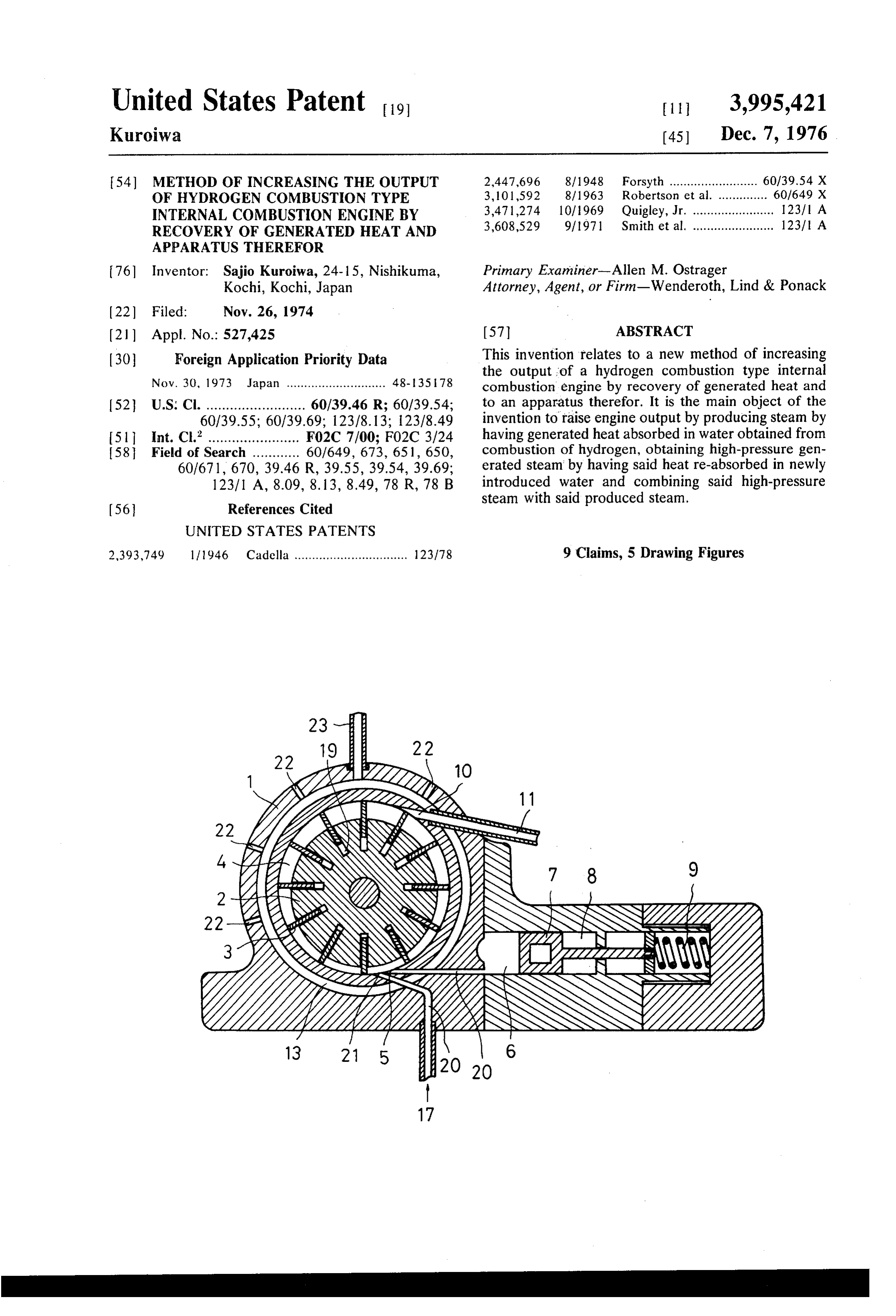
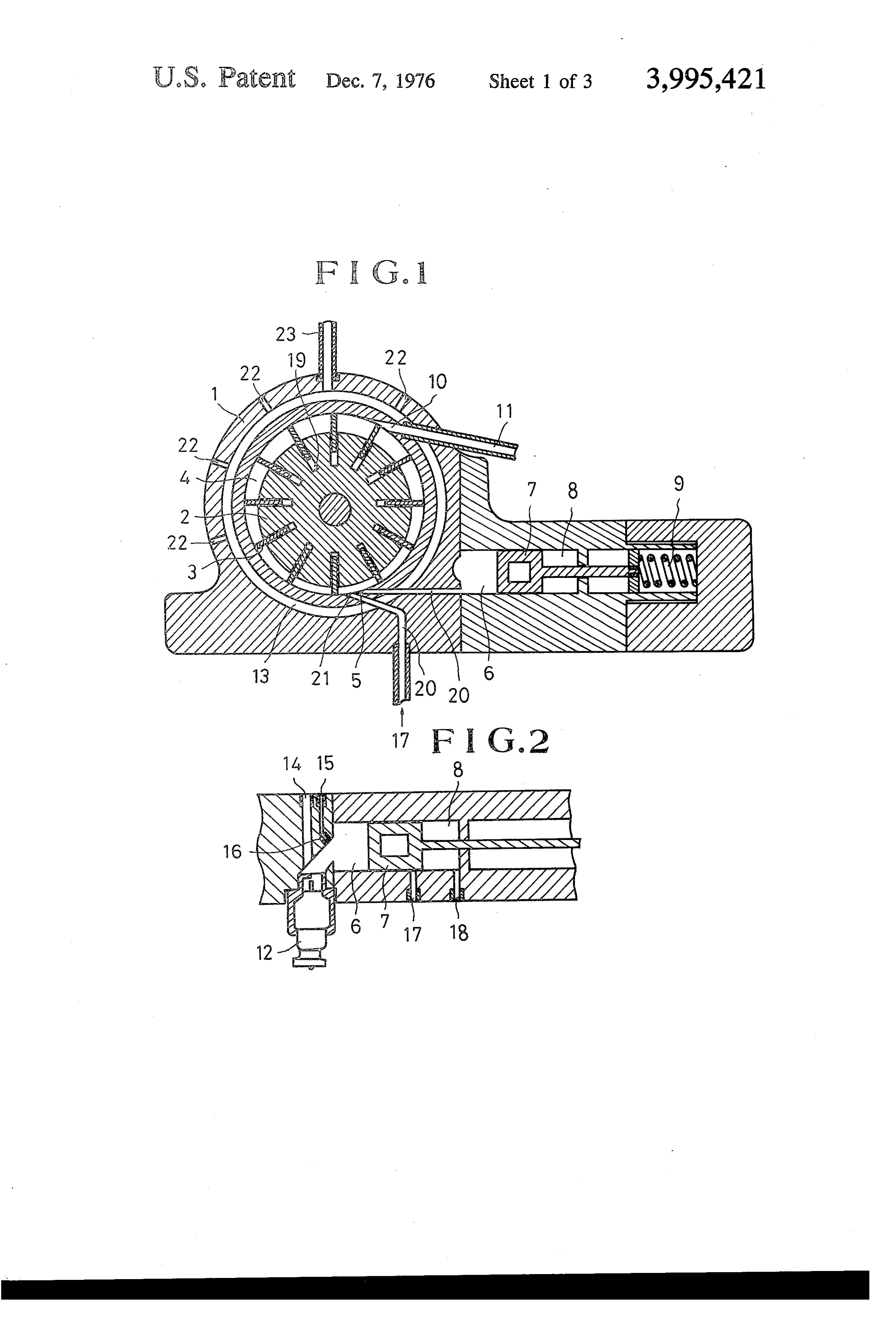
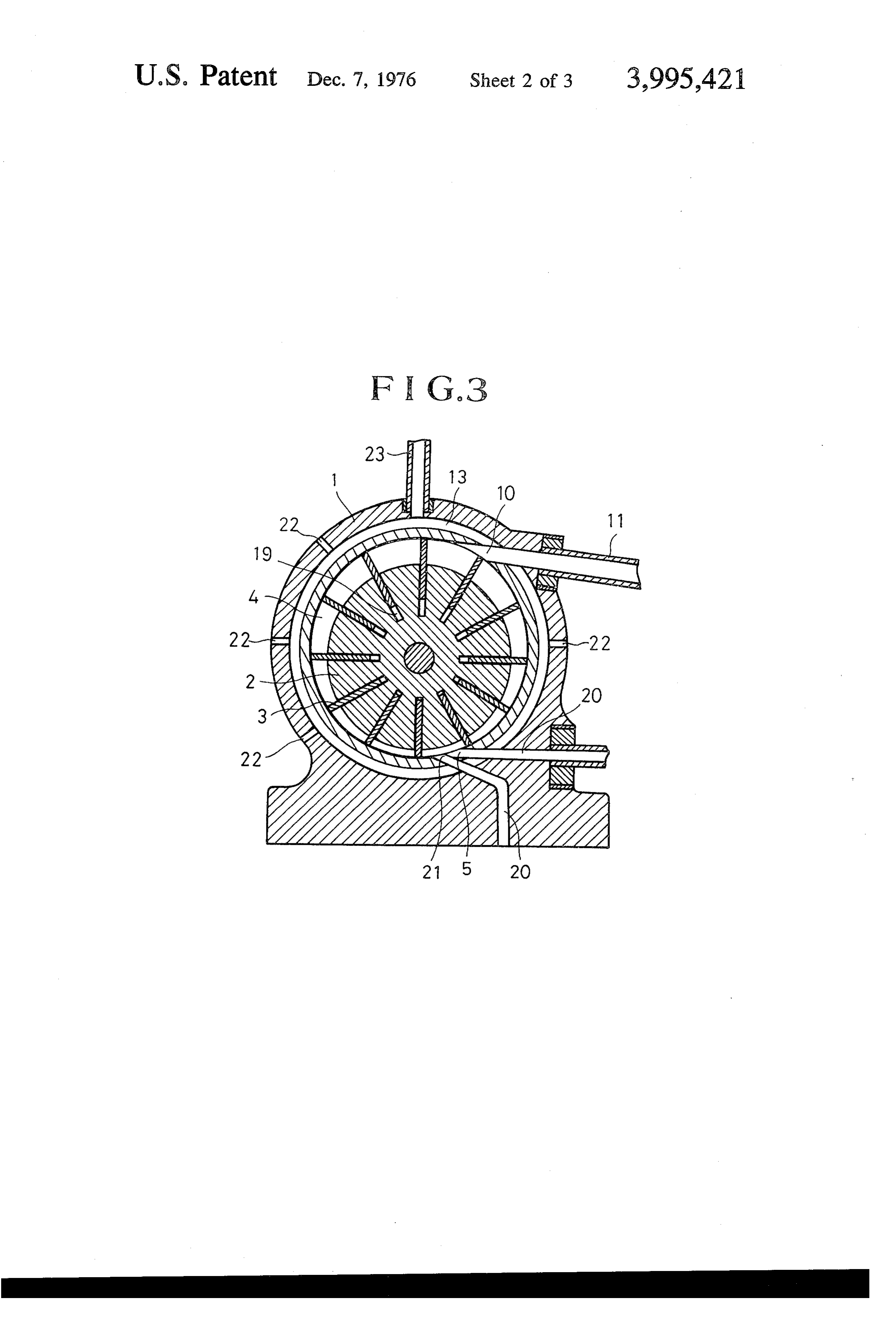
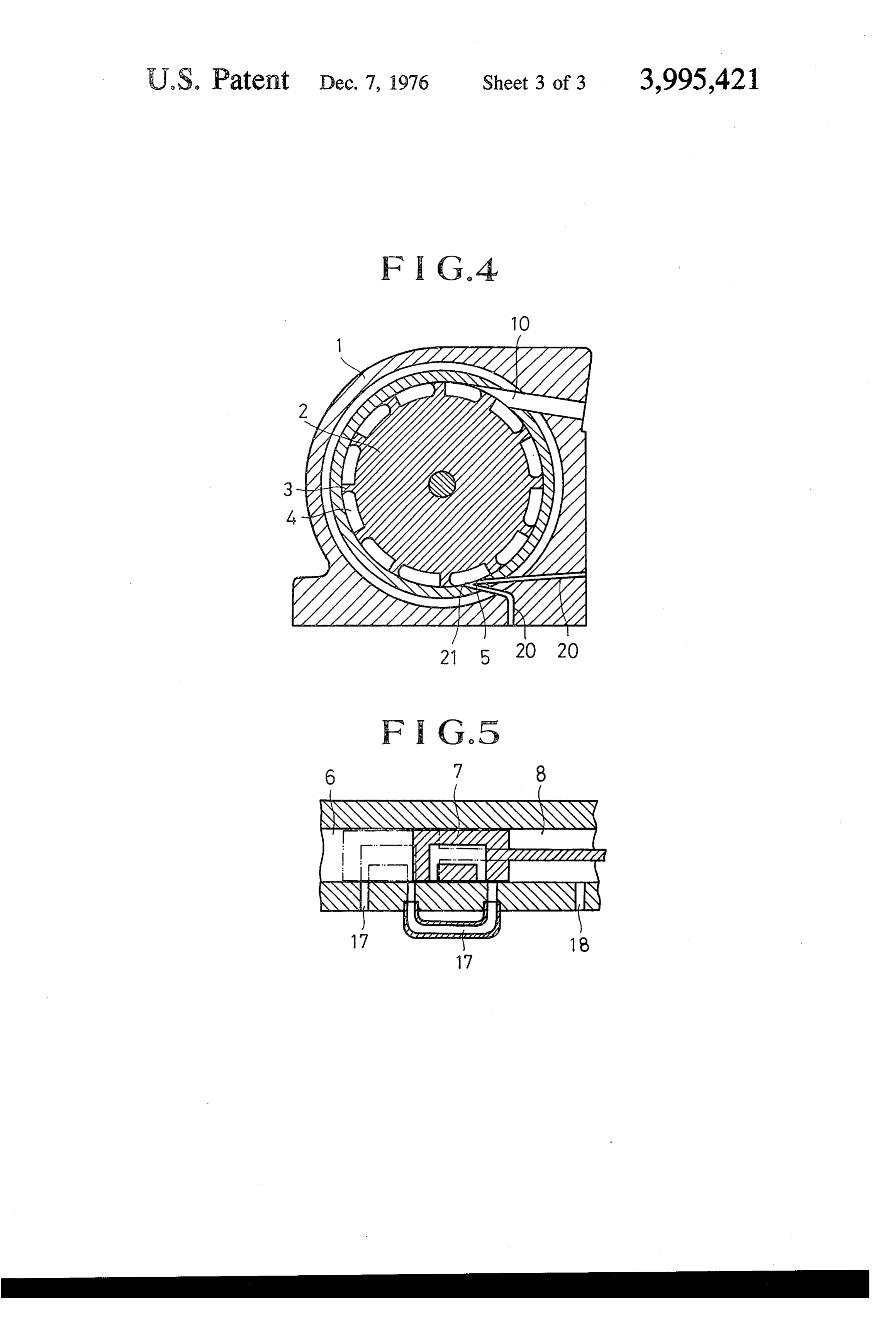
The accompanying drawing illustrates the basic prin is under high pressure due to the prescence of said ciples of the method a increasing the output of hydro produced steam and generated steam. Said high-pres gen type internal combustion engine and an apparatus sure steam passes through passage 20 and is ejected in therefore according to this invention, wherein: the form of a high-speed jet from ejecting port 5 in the FIG. 1 and FIG. 3 are schematic longitudinal sec direction of spaces 4 of engine casing 1 defined be tional views showing an example of a high-pressure and tween rotor 2 and adjacent radial projecting members 3. This energy gives to rotor 2 a powerful rotating mo low-pressure hydrogen engine, respectively;
FIG. 2 is a cross sectional view showing an example tion in the direction of the steam ejection. Vane mem of the hydrogen combustion and steam generating cyl bers 3, in FIGS. 1 and 3 as rotor seals and press tightly inder part thereof; 10 on the inner surface of the engine casing 1 due to cen FIG. 4 is a schematic longitudinal sectional view trifugal force and seal the gradually enlarging spaces showing an example of the engine having concentri between the vanes 3. Steam is exhausted through steam cally rotating rotor; and exhausting ports 10 provided at suitable locations in FIG. S a schematic sectional view showing an exam engine casing 1 and can flow into a low-pressure engine ple of the piston valve for exhausting the generated 15 through pipe 11 for further use.
steam injected on the back side of the piston in the Piston 7 is supported by coil spring 9 in cylinders 6 engines of FIGS. 1, 3 and 4. and is provided when necessary when the volume of steam to be used and the volume of steam to be gener
DESCRIPTION OF PREFERRED EMBODIMENTS ated must be increased so as to increase engine output. In this description, steam utilized in the engine is Piston 7 is a device serving to protect steam generating
designated according to the manner of generation. cylinders 6 against impact pressure (breaking pressure) Steam is either produced steam or generated steam. caused by hydrogen combustion and the instantaneous The former is the steam produced by the absorption of generation of high-pressure steam by introduction of generated heat by water produced at the time of hydro water or steam, by equalizing the pressure of generated gen combustion, whereas the latter is the steam pro 25 steam to some extent and prolonging the ejecting time duced by the absorption of said generated heat by in to some extent. This device is not necessary in some troduced water. 'Generated heat" is the general term cases. An accumulator may be used to fulfill the above for the heat energy produced by hydrogen combustion functions of this device in some cases. When it is neces for the frictional heat produced between moving parts 30 sary to increase the output by continuous steam ejec tion, a plurality of steam generating cylinders are pro of the internal combustion engine.
vided and connected to engine casing 1 either in series
EXAMPLE I - A ROTARY TYPE HYDROGEN or in parallel.
ENGINE This invention provides another method of obtaining As illustrated in FIG. 1, hydrogen is burnt by provid high-pressure generated steam by using introduced ing rotor 2 supported an an eccentric shaft in engine 35 water as described below. The high pressure engine or casing 1, forming radial grooves 19 in said rotor 2, low-pressure engine has engine casing 1 with a double fitting rotor vanes 3 freely slidably in grooves 19 in gas wall construction, as shown in FIG. 3. An annular space tight relationship therewith, alternatively, as shown in 13 is formed around the rotor chamber, said annular FIG. 4, the shaft can be concentric and rotor 2 can space 13 being provided with one or more water or have a multitude of radially protruding integral mem 40 steam introducing ports 22 and also with exhausting bers 3 around the periphery of rotor 2. Said valves or port 23 at a suitable location. Water or steam is inter protruding parts 3 are slidable on the inner surface of mittently injected in the form of drops or mist into engine casing 1, which in turn has more steam ejecting annular space 13 so as to absorb the generated heat of ports 5 and steam exhausting ports 10 at suitable loca engine casing 1 and cool it, and steam is instanta tions around the engine casing 1. The engine has one or 45 neously generated to recover part of the heat energy. more hydrogen combustion and steam generating cyl This generated steam (recovered steam) is injected inders 6, said cylinders being connected to engine cas throughinto back chamber 8 of pressure regulating piston 7 ing 1 through ejecting ports 5. As shown in FIG. 2, exhausting port 23 and generated steam inject hydrogen gas and air or oxygen as an oxidizing agent ing port 18 provided in cylinder 6 and connected to are introduced into each cylinder 6 by an injection exhausting port 23, as shown in FIG. 2 and FIG. 5, and pump, valve and supply pipe 14 by injection under becomes generated steam having a higher pressure pressure or suction and the hydrogen is ignited by igni after re-absorbing the heat generated in the back part tion device 12 provided in cylinder 6. The produced of piston 7 and cylinder 6. This high-pressure generated water obtained from hydrogen combustion absorbs the 55 steam helps advance piston 7. The steam produced in the front part of piston 7 is injected under pressure into heat produced at the time of hydrogen combustion and the engine through ejecting port 5 by said advancing the generated heat such as the frictional heat generated force. Also, exhausting port 17 is opened when piston between the moving component parts of the engine and instantaneously becomes steam and expands. (This 7, has advanced, e.g. up to the imaginary line portion in steam will be hereafter called produced steam.) Simul FIG. 5 and thereafter the high-pressure generated taneously with this combustion or after this combus 60 steam piston which has served as the force to propel said is injected into engine through steam injection tion, a small volume of water or steam is introduced into cylinder 6 through pressure water pipe 15 and nozzle 21 connected to exhausting port 17. It is also injection nozzle 16 under pressure, suction or dripping. possible into the to have this generated steam injected directly engine casing from exhausting port 23 through
The water or steam thus introduced into cylinder 6 absorbs said produced heat and generated heat such as 65 ejecting port 21. Needless to say, this generated steam frictional heat occurring inside cylinder 6 and in the can be obtained not only in engine casings such as the cylinder body and piston instantaneously becomes one described above but also by recovering heat, using steam and expands. As a result, the inside of cylinder 6 water as the medium for absorbing heat, from parts like
Page 7
S 6 engine blocks and engine housings or from cylinders the interior wall surface of said engine chamber for and other places which are heated with generated heat partitioning said annular space; at least one cylinder by thermal conduction. (The general term for these spaced from said engine: chamber and defining a com parts is internal combustion engine structure.) The bustion chamber; a cushioning piston reciprocally mov construction of a low-pressure engine can be identical able within said cylinder for adjusting the volume of to that of the above described high-pressure engine. said combustion chamber and accommodating the For example, a low-pressure engine can have the con pressure formed therewithin, said cylinder having a struction as shown in FIG. 3 which is the same as the rear cylinder space on the opposite side of said cush construction of the high-pressure engine except that ioning piston from said combustion chamber; means on the low-pressure engine does not have the steam gener 10 said cylinder for supplying hydrogen gas and oxygen ating cylinders 6. In this case, the steam exhausted from containing gas to said combustion space and ignition the high-pressure engine through exhaust pipe 11 is means on said cylinder for causing said hydrogen gas to received through passage 20 and is exhausted through be combusted within said combustion, chamber, exhausting port 11 after it. has rotated rotor 2 in the thereby producing water vapor therefrom; means on same way as described above. The space 4 between 5 said cylinder for supplying water in a form no more rotor 2 and engine casing 1 in this case should prefer volatile than water vapor of a low temperature for ably be somewhat larger than in a high-pressure engine producing water vapor by absorbing heat generated so that the steam can fulfill said function while being from said combustion of said hydrogen gas within said expanded. combustion chamber; the end of said cylinder having The steam which is exhausted from the low-pressure said combustion chamber therein being connected to engine through exhausting port 11 is sometimes con said engine chamber for directing the water vapor ob densed by a steam condenser to raise the engine effi tained from said combustion chamber into said annular ciency and the water obtained from condensation is space within said engine chamber for rotating said reused. The ignition device 12 may be any of various rotor by the combinedjet energy and expansion energy known types. For example, the conventional method in 25 of the thus obtained water vapor; exhaust means open which the generator or battery is used as the power ing out of said annular space for exhausting said water source and an ingition coil is used as a high-tension vapor from said engine chamber after it has rotated current igniter or a new method in which a piezo-elec said rotor within said engine chamber; a wall encircling tric element is used to facilitate ignition may be em said engine casing and defining a space therearound ployed. shut off from the atmosphere; means on said wall for supplying water in a form no more volatile than water
EXAMPLE II - A RECIPROCATING ENGINE vapor at a low temperature into said space for cooling Although not illustrated in particular, the hydrogen down said engine casing and producing a Secondary engine according to this invention can be readily em water vapor and thereby absorbing the heat generated bodied as a conventional reciprocating engine with 35 in said engine casing; means coupled between said wall minor changes thereof. Air is first sucked into a con and said cylinder for directing secondary water vapor ventional cylinder and, at the last stage of the suction of generated within said space out of said engine casing air, hydrogen gas is injected under pressure or sucked and introducing it into said rear cylinder space; and into the cylinder. means coupled between said cylinder at a point adja Then the gas is ignited by an ignition device and 40 cent the rear side of said piston at its position closest to exploded. In this case, the ignition time must be much said engine casing and said engine casing for supplying later than with a gasoline engine because hydrogen said secondary water vapor to said annular space in reacts so fast compared with gasoline that detonation said engine casing; whereby the secondary vapor exerts will occur at the same time as ignition. A small quantity a pressure on said cushioning piston which is added to of water pessurized by a pump such as a Milton-Roy 45 the pressure of the water vapor in the combustion pump is injected or sprayed into the cylinder simulta chamber to increase the energy of the water vapor in neously with ignition. At the same time, pressurized the combustion chamber as it is ejected into said annu water is injected intermittently into each engine block lar space in said engine casing, and the secondary water to generate steam so as to cool the engine and effec vapor after it has exerted its pressure on said cushion tively utilize the heat energy generated in each engine 50 ing piston is conducted to said annular space in said block. This steam can be supplied to the cylinder engine casing to act on the rotor directly, thereby in through a pipe and valve. As the valve is opened in the creasing the output power of said engine. expansion process, the steam is injected into the cylin 2. The apparatus as claimed in claim 1 further com der to serve to increase engine output and decrease the prising a low pressure engine rotor, and means for generation of nitric oxide. In this case, a radiator and 55 supplying the water vapor from the exhaust means of other attachments to the conventional engine become said engine casing for rotating said low pressure engine unnecessary. rotor, whereby said low pressure engine rotor produces What I claim is: further output power.
1. An apparatus for improving the output of a hydro 3. The apparatus as claimed in claim 1, further com gen combustion type internal combustion engine by 60 prising means for circulating water in a form no more recovery of generated heat, which comprises: an engine volatile than water vapor at a low temperature as a heat casing defining an engine chamber adapted to be sepa absorbing medium from one portion of the engine rated from the atmosphere; a rotor rotatably supported structure having a relatively low temperature in succes therein and defining an annular space between the sion through other portions of the engine structure circumferential surface of said rotor and the inner Sur 65 relatively higher temperatures for recovering heat and face of said engine chamber; a plurality of vane mem obtaining water vapor, and supplying said water vapor bers projecting radially outwardly from the outer cir into said engine chamber rear cylinder space for in cumference of said rotor and slidably sealing against creasing the output power of said rotor.
Page 8
4. The apparatus as claimed in claim 1, further com ery of heat generated therein, which comprises the prising means for circulating water in a form no more steps of; generating water vapor by combustion of hy volatile than water vapor at a low temperature as a heat drogen gas in a combustion chamber which is com absorbing medium from one portion of the engine pletely shut off from the atmosphere; supplying water structure having a relatively low temperature in succes in a form no more volatile than water vapor of a low sion through other portions of the engine structure temperature into said combustion chamber and in relatively higher temperatures for recovering heat and creasing the temperature thereof by absorption of heat obtaining water vapor, and supplying said water vapor generated by said combustion of said hydrogen gas; into said engine chamber engine chamber space for joining the water vapor obtained by said two steps and increasing the output power of said rotor. 10 ejecting the thus obtained water vapor into an engine 5. The apparatus as claimed in claim 1 wherein said chamber also completely shut off from the atmosphere cylinder further has a spring therein urging said cush and independent from said combustion chamber and ioning piston toward said engine casing for obtaining an having a rotor therein for rotating said rotor so as to improved cushioning effect. produce a rotating output power; supplying water in a 6. The apparatus as claimed in claim 1 wherein said 15 form no more volatile than water vapor of a low tem cushioning piston has a passage therethrough for con perature into a space within the structure composed by ducting water vapor introduced into said rear cylinder said engine chamber and surrounding said engine space to pass therethrough, whereby heat generated in chamber for absorbing the heat generated in said struc said piston during passing of water vapor therethrough ture comprised by said engine chamber for obtaining a is recovered and supplied to said engine chamber. 20 secondary water vapor; recovering said secondary 7. The apparatus as claimed in claim 1 wherein said water vapor obtained from absorbing heat from said plurality of vane members partitioning said annular engine and introducing it into the space behind a cush space of said engine chamber extend radially outwardly ioning piston in a cylinder coupled to said engine cham from the outer circumference of said rotor and are 'ber for reuse for causing said cushioning piston to be slidable toward and away from the outer circumference 25 advanced for forcing the generated water vapor into of said rotor so that the ends of said vane members said engine chamber with a greater force than without constantly and sealingly contact contacting the interior said water vapor being introduced behind said cushion wall surface of said engine chamber. ing piston and causing said rotor to be rotated with a 8. The apparatus as claimed in claim 1 wherein said greater force; and therefore ejecting the secondary plurality of vane members partitioning said annular 30 water vapor from behind said cushioning piston space of said engine chamber are integral with said through an independent passage communicating with rotor and extend radially outwardly from the outer said engine chamber into said engine chamber, circumference of said rotor. whereby said rotor is caused to produce further rotat 9. A method of improving the output of a hydrogen ing output power. 2k ck 3k >k xk combustion type internal combustion engine by recov 35
Provenance
- Collection
- Cited prior art
- Original PDF
- patentimages.storage.googleapis.com →
- Filed
- 1974-11-26
- Pages
- 8
- Method
- pdftotext (the PDF's own text layer) + pdftoppm 300dpi page scans
- Source
- Google Patents bibliographic record
- Granted
- 1976-12-07
- Inventors
- Sajio Kuroiwa
- Transcribed from
- patentimages.storage.googleapis.com →