patent · US3897757
Conversion device enabling a gasoline engine to be fueled with hydrogen
5 August 1975
Page 1 — bibliographic record
United States Patent (19) (11 3,897,757 Abello (45) Aug. 5, 1975
54 CONVERSION DEVICE ENABLING A 2.937,634 5/1960 Kelseaux...................... 23/DG 2 GASOLINE ENGINE TO BE FUELED WITH 3.572,297 3/1971 Murray ............................... 123/1 A HYDROGEN 3,665,896 5/1972 Crehore.............................. 123 fi A 3,665,896 5/1972 Crehore....................... 123/DIG. 12 (75) Inventor: Lawrence Abello, Bombay, India FOREIGN PATENTS OR APPLICATIONS 73) Assignee: Canadian Jesuit Missions, Toronto, 865,413 4/1961 United Kingdom................. 23/120 Canada 83 429 9, 1938 France........................ 23/DIG. 12
Primary Evantiner-Charles J. Myhre (21) Appl. No.: 332,815 Assistant Evaminer-R. H. Lazarus Attorney, Agent, or Firn-Spencer & Kaye (30) Foreign Application Priority Data
Oct. 20, 1972 Canada................................ 154350 57 ABSTRACT A mechanism allows a simple gasoline engine to be 52 U.S. Cl........................... 123/1 A; 123/DIG. 2 converted to run using hydrogen as a fuel by the intro 51 Int, Cl. . . . . . . . . . . . . . . . . . . . . . ....................... F02b 75/2 duction of a pulse of hydrogen during the intake 58) Field of Search 3 - - - - - - 123/120, 121, A, 129, stroke. The mechanism is such that an engine may use 123/139 H, 27 GE, 90.1, DIG. 12 either fuel at will but preferably simple changes to the cylinder head allow an engine to be converted into a 56 References Cited high compression engine using hydrogen alone be UNITED STATES PATENTS cause of the greater efficiency.
1,340,444 5/1920 Hayes................................. 23/129 2,852,013 9/1958 Davids ................................ 23/120 7 Claims, 6 Drawing Figures
Page 2
Drawing sheet — no readable text.
Page 3
Drawing sheet — no readable text.
Page 4
Drawing sheet — no readable text.
Page 5
Drawing sheet — no readable text.
Page 6
CONVERSION DEVICE ENABLING A GASOLINE is drawn open by suction on the inlet stroke. The ex ENGINE TO BE FUEED WITH HYDROGEN haust valve 16 has a fairly heavy spring 18 to keep it tightly shut and is operated by a push rod 20 through
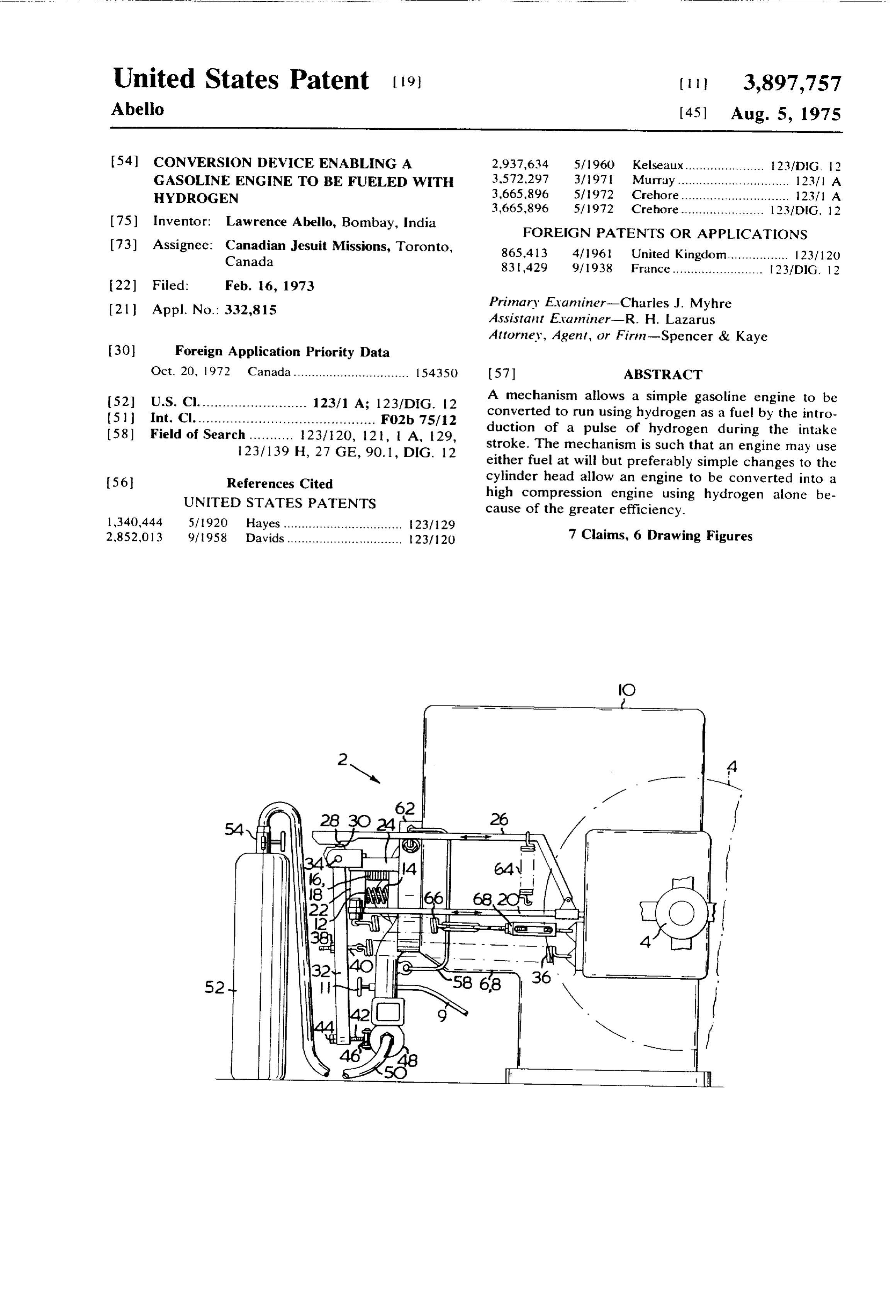
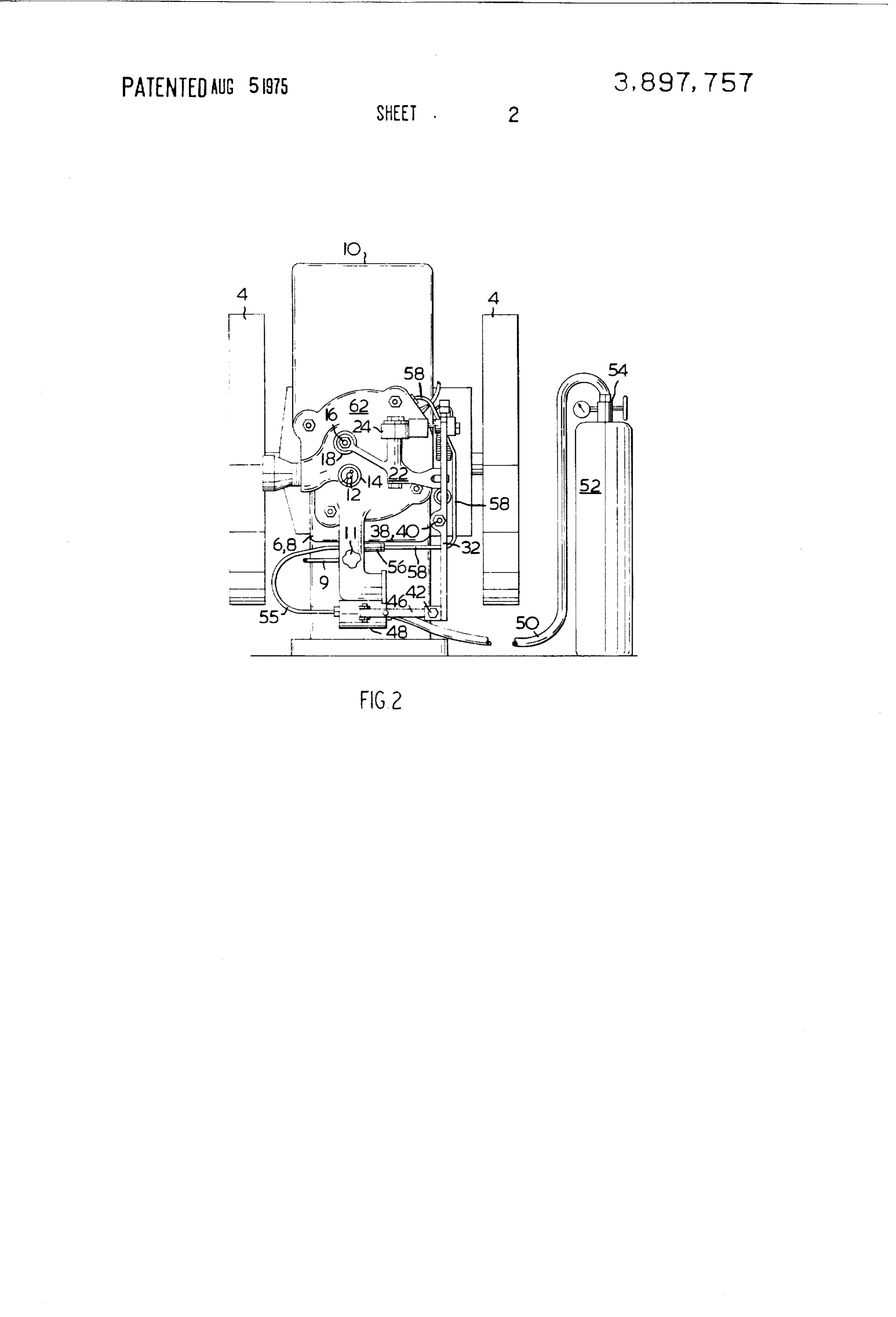
This invention relates to gasoline engines, and in par a rocker arm 22 mounted on bracket 24. The push rod ticular to stationary engines. Such engines are used on is driven by a cam through a 2-to-1 reduction gear from outlying farms for pumping water, generating electric the crankshaft on which flywheel 4 is mounted. ity and like tasks, and are usually of the four stroke, sin Turning to the modification, an operating arm 26 is gle cylinder type. pivotally mounted on the push rod 20. This arm has a It is well known that such engines have disadvantages latch 28 on it which engages catch 30 on the end of although their use is exceedingly widespread. For in O trigger arm 32. This trigger arm is mounted on shaft 34 stance, the hydrocarbon nature of gasoline fuel re which fits into a bracket bolted to the rocker arm quires that such engines be decarbonized regularly; due mounting bracket 24.
also to the hydrocarbon fuel the exhaust is noxious - The trigger arm 32 is functionally a light hammer that is, the carbon monoxide which is inevitably gener with a predetermined impulse given to it by a tension ated can build up to lethal concentrations in enclosed 5 ing trigger spring 36. The setting of this spring can be spaces; thus, exhaust pipework is needed if the engine adjusted to vary the impulse by adjustment nut 38 on is to be serviced while running, as a weatherproof shel eyebolt 40, and is normally such that the impulses re ter is required for ignition protection. Miscellaneous semble tapping rather than repeated hammer blows. hydrocarbons in the exhaust also pollute the atmo A striker bolt 42, with an adjustable nut 44, is located sphere, as is also well known. 20 near the end of the trigger arm 32 and when the latch Many proposals have been made to use hydrogen as 28 releases the trigger arm the striker taps a pivotally a fuel, but these have required such elaborate modifica mounted metering valve depression arm 46, momentar tions as to be virtually specially built engines, typical ily depressing it to operate as by a tapping impulse, a examples being U.S. Pats. Nos. 2, 183,674; 3,471,274 spring loaded metering valve 48. Trigger arm 32 strikes and 3,572,297. 25 the valve depression arm 46 with a force which de
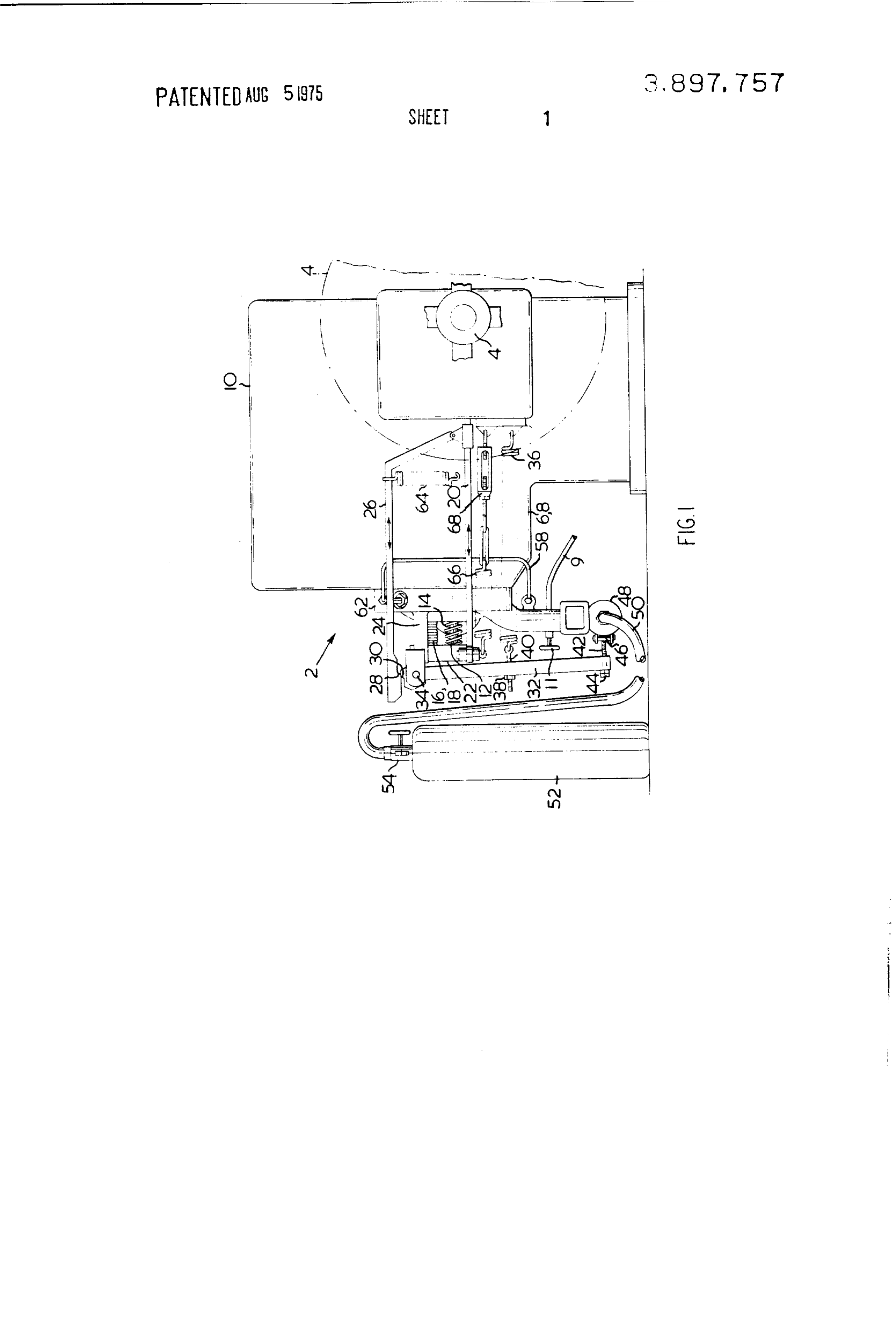
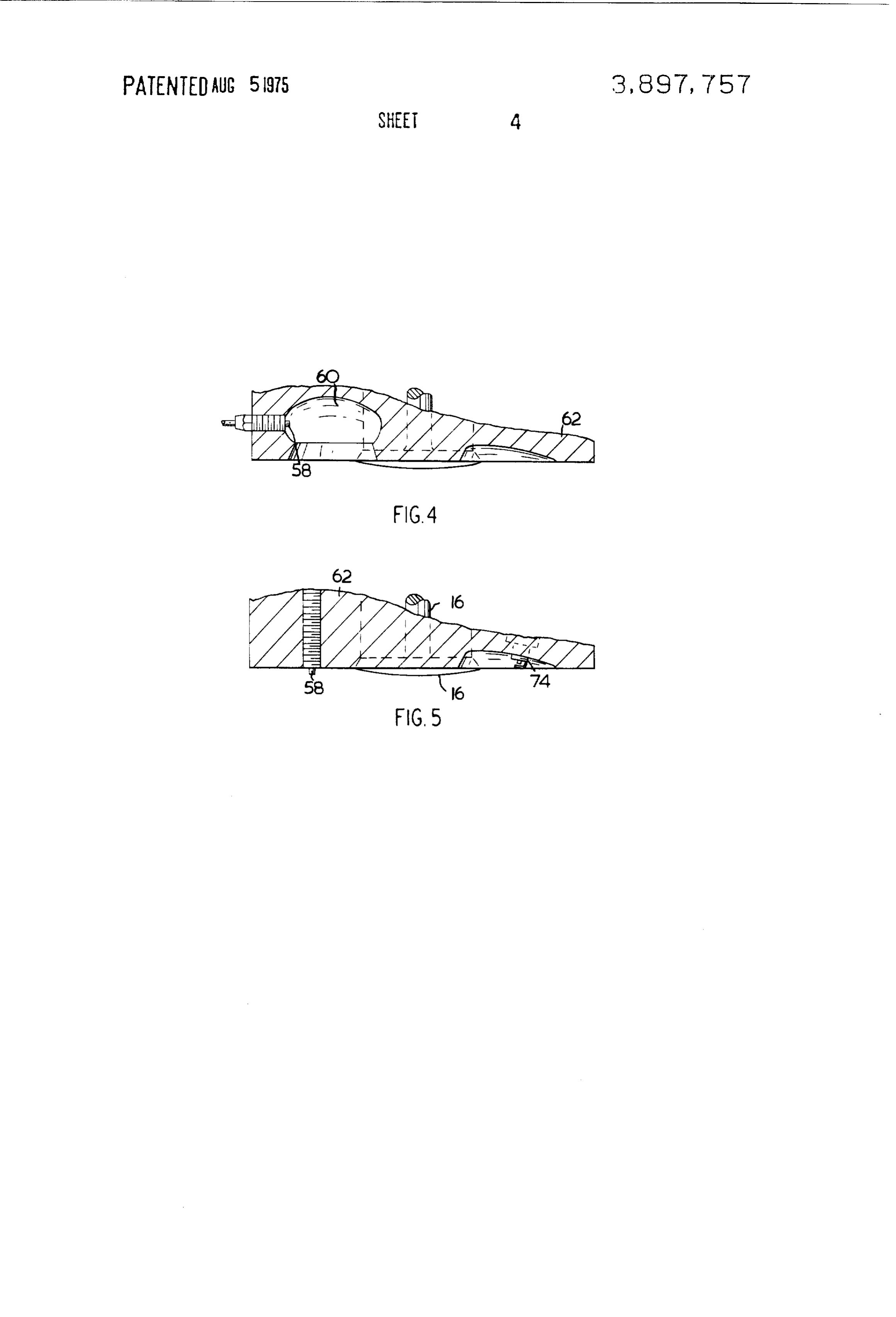
Such prior art so deeply underscores the likelihood pends only on the tension of spring 36 and its own mass of detonation, and the difficulty of efficient mixing that and therefore the impulse which it produces for open the possibility of using hydrogen as fuel in a simple en ing the valve is independent of the engine speed. In this gine would seem to be remote. way, the valve is opened for a brief period which is sub An object of this invention is to solve these problems 30 stantially independent of the engine speed. by injecting a charge of unmixed hydrogen during the This metering valve is fed by a line 50 from hydrogen intake stroke. This not only ensures good mixing and bottle 52, or any other suitable supply of pressurized inhibits detonation and preignition but also allows a hydrogen gas. A pressure regulator 54 is set to 120 psi simple conversion from a gasoline engine. so that a regulated hydrogen pressure is established at A more limited object of this invention is to provide the metering valve 48. When this valve is depressed a dual fuel engine - that is, one that will run on either momentarily, by reason of the impulse behind striker hydrogen or gasoline. bolt 42, a burst of hydrogen passes through line 55, The invention will be more easily understood after non-return valve 56 and line 58, which is a copper tube, reading the following disclosure and referring to the directly into the combustion chamber 60 of the cylin drawings which illustrate, by way of example, an engine 40 der head 62, see FIG. 4.
which incorporates an embodiment of the invention. The basic operation of the engine will now be under FIG. 1 is a side elevation of a typical horizontal one stood. When running on hydrogen is desired the gaso cylinder engine modified according to the teachings of line supply is turned off and the hydrogen supply is the invention, turned on. Preferably the spark is retarded somewhat, FIG. 2 is a front end view of the engine looking on the 45 for optimum operation on hydrogen. When reverting to cylinder head; gasoline the spark should be advanced, that is timed in FIGS. 3a and 3b are an enlarged view of a portion of accordance with the spark timing mark on the engine FIG. 1 with the mechanism in two different positions, flywheel.
F.G. 4 is a scrap section view of the cylinder head, 50 When the engine is cranked to start it, the first move FIG. 5 is the cylinder head of an alternative embodi ment of the exhaust valve push rod 20 towards the ment.
crankshaft of flywheel 4 draws operating arm 26 with
In these Figures the usual components of such an en the push rod and the latch 28 of the operating arm 26 gine 2 will be easily identified. Flywheel 4 is driven by engages catch 30 on the end of trigger arm 32 and is a crank and piston, not shown, because the cylinder is 55 held in place by spring 64; this position is seen at FIG. surrounded by an integral crank case and cylinder 3a.
jacket 6, 8. A header tank 10 holds a reservoir of cool To incorporate the invention in this particular en ing water for the cylinder. The engine is actually a John gine, it happens that another spring 66 is needed with Deere, type 'E' 1/2 horsepower gasoline engine, but a turnbuckle 68 to adjust it. The reason is that the ex the conversion to be described below can be carried haust valve push rod 20 also operates the igniter by fur out on any similar engine. For this reason details of ther travel after the exhaust valve itself has closed, and standard fittings, such as the ignition, the simple carbu the torsional spring (not shown to avoid confusion - retor, manual choke and the like, will be omitted from it fits round about the circular bearing portion of the description. However, the gasoline line 9 with the rocker arm 22) is not strong enough to overcome the carburetor needle valve handwheel adjuster l l have 65 loading of tensioning trigger spring 36. Although this been numbered for easy identification. spring 36 is quite light - it only has to accelerate the In this engine the inlet valve 12 has a light spring 14 trigger arm to provide a tapping type of impulse - it to bias it shut, but does not have an operating rod and acts at such a mechanical advantage that it can hold the
Page 7
push rod 20 off from following the operating cam sur made therein without departing from the invention as face fully; although it is not strong enough to hold the defined by the appended claims. exhaust valve open, it can and does prevent the lighter claim:
torsion spring from urging the push rod further to oper 1. A positive displacement internal combustion en ate the igniter (also omitted for clarity). 5 gine adapted to use hydrogen gas comprising: As the exhaust valve push rod 20 moves towards the means for controlling the admission of air to a com crankshaft of flywheel 4, the elbow 70 of the trigger bustion space thereby defining an air intake stroke; arm catch 30 pushes the latch 28 off the catch and the a hydrogen supply means, trigger spring 36 accelerates the trigger arm so that bolt means for connecting said hydrogen supply to said 42 taps the metering valve depression arm 46 when the O combustion space, inlet stroke has begun and the burst of hydrogen actu means for predetermining a time during the air intake ally enters the cylinder at about 40 after TDC. This po stroke, sition is shown in FIG. 3b. It will be understood that a normally closed valve means in said hydrogen sup triggering the tapping impulse by the exhaust valve ply connecting means;
push rod with its continuing travel beyond exhaust 5 means for opening said valve means for a brief period valve closure allows a range of timing to be achieved. which is substantially independent of the engine It may be necessary to raise or lower the regulator speed; and pressure to ensure that the mixture is neither too rich means connecting said time predetermining means to nor too lean, the trigger arm spring 36 is also provided said valve opening means whereby a pulse of hy with an adjustable feature so that the impulse can be 20 drogen is produced and conveyed to said combus varied, and to some extent these represent alternative tion space, at a predetermined time during the air adjustment of mixture strength. The igniter adjustment intake stroke.
is, of course, independent of mixture strength, and de 2. An engine as claimed in claim 1 wherein the com pends upon which fuel the engine is using. pression ratio is low enough to allow gasoline to be The above describes a dual fuel type of engine - in the used as an alternative fuel.
sense that it can use both types of fuel. However, in an pression 3. An engine as claimed in claim 1 wherein the com other high compression embodiment the engine, al ratio is high enough to increase cycle effi. though only able to use hydrogen, has a greater fuel ef ciency above that attainable in a gasoline fueled en ficiency by the substitution of a high compression head. gine.
By high compression a ratio higher than 12 to 1 is 30 4. An engine as claimed in claim 1 wherein said valve meant and a suitable ratio has been found to be 13:1. means comprises a spring loaded plunger operated me This is achieved by removing the igniter (not shown) tering valve and said valve opening means is adapted to and then filling in the combustion chamber 60. Instead deliverS. an impulsive blow to the plunger of the valve of the igniter which functions as both a spark plug and 5. An engine as claimed in claim 1, wherein said en breaker points, spark plug 74 was provided and the original magneto was replaced by a magneto which gine comprises an exhaust valve and operating means contained breaker points. The low compression head therefor, and wherein the means for predetermining a and the high compression modification are illustrated time during the intake stroke comprises a means con in FGS. 4 and 5. nected to the exhaust valve operating means, whereby Other mechanical adjustments were made which do 40 production of a pulse of hydrogen is initiated by the re not concern the invention directly, for instance, a liner turn stroke of said exhaust valve operating means. was inserted to reduce the displacement. It was consid 6. An engine as claimed in claim 1 wherein said en ered that raising the compression ratio from the origi gine comprises an exhaust valve and operating means nal 4:1 to 13:1 without other modification would therefor, and wherein said valve means comprises a merely invite premature failure of a connecting rod, 45 spring loaded plunger operated metering valve, and main bearings or crankshaft which had been designed said valve opening means comprises a trigger arm hav for the lesser duty. Moreover the 13:1 ratio does not ing a catch and a latch means connected to the exhaust represent the thermodynamic limit as a few tests indi valve operating means, said latch means being adapted cated that the hydrogen did not ignite spontaneously to engage the trigger arm catch as the exhaust waive op even at a 16:1 ratio in contrast with the prior art teach 50 erating production means undergoes a return stroke, whereby the of a pulse of hydrogen gas is initiated.
lings.
Thus, while there has been shown and described what 7. An engine as claimed in claim 6 wherein an elbow is at present considered the preferred embodiment of portion of the trigger arm forms a releasing means for the invention, it will be obvious to those skilled in the releasing the catch. k k xk ck k art that various changes and modifications may be 55
Provenance
- Collection
- Cited prior art
- Original PDF
- patentimages.storage.googleapis.com →
- Filed
- 1973-02-16
- Pages
- 7
- Method
- pdftotext (the PDF's own text layer) + pdftoppm 300dpi page scans
- Source
- Google Patents bibliographic record
- Granted
- 1975-08-05
- Inventors
- Lawrence Abello; CANADIAN JESUIT MISSIONS
- Transcribed from
- patentimages.storage.googleapis.com →