patent · US4127453
Conversion of available energy
28 November 1978
Page 1 — bibliographic record
United States Patent (19) (11) 4,127,453 Radebold (45) Nov. 28, 1978 (54 CONVERSION OF AVAILABLE ENERGY namically useful) is focussed by an inflated, buyont 76 Inventor: Reinhart Radebold, Quastenhornweg reflector for heating lithium circulating through an 14 a, 1 Berlin 22, Fed. Rep. of MHD conversion system. Hydrogen and nitrogen are Germany added to the heated lithium, finely divided iron serving as catalyst to obtain lithium amid. The hydrogen has 21 Appl. No.: 545,133 been produced by electrolysis of water. The lithium (22 Filed: Jan. 29, 1975 lithium amid mixture (liquid) is mixed with pressurized (30) Foreign Application Priority Data nitrogen to obtain a two phase flow in which the liquid is accelerated; focussed into a jet passing through the
Jan. 30, 1974 DE Fed. Rep. of Germany ....... 2405134 MHD converter to obtain hydrazine and additional 51) Int. Cl. ......................... C25B 1/00; C01B 21/16 electrical energy e.g. for the hydrogen electrolysis; and 52 U.S. Cl. .................................... 204/59 R; 204/63; returned to the solar heater. The gas (N2) is separated; 423/407; 423/413; 310/300 subjected to recuperative heat exchange with itself; and (58) Field of Search .................. 423/407, 413; 204/63, low temperature isothermic compression under direct 204/59 contact with a liquid which in turn is, ultimately, air
References Cited cooled. The entire assembly is of elongated construc 56) tion wherein the main active elements are arranged
914,214 3/1909 Acker ................................... 423/413 rounded by smaller tubing which section-wise runs 2,779,661 l/1957 Robell .................................. 423/407 various fluids to their appropriate destinations while 3,034,861 5/1962 Pursley ........ ... 204/59 RUX serving as support frame. The entire process runs on the 3,542,512 11/1970 Honeycutt ........................... 423/413 basis of self-sustaining fluid circulations without mov FOREIGN PATENT DOCUMENTS ing parts; the thermo and hydrodynamics as well as the electromagnetic interactions are explained and mathe 55,144 9/1910 Switzerland ............................. 423/413 matically analyzed. The use of hydrazine as universal 25,891 of 1912 United Kingdom ..................... 423/43 fuel is explained on the basis of compatibility with the Primary Examiner-F.C. Edmundson biosphere. Alternative modes of hydrazine synthesis Attorney, Agent, or Firm-Smyth, Pavitt, Siegemund, including using nuclear reaction as primary heat source Jones & Martella is discussed.
Solar energy (called exergy to the extent it is thermody 50 Claims, 42 Drawing Figures
SOLARAADATION
27s. AIR
Page 2
Drawing sheet — no readable text.
Page 3
Drawing sheet — no readable text.
Page 4
Drawing sheet — no readable text.
Page 5
Drawing sheet — no readable text.
Page 6
Drawing sheet — no readable text.
Page 7
Drawing sheet — no readable text.
Page 8
Drawing sheet — no readable text.
Page 9
Drawing sheet — no readable text.
Page 10
Drawing sheet — no readable text.
Page 11
Drawing sheet — no readable text.
Page 12
Drawing sheet — no readable text.
Page 13
Drawing sheet — no readable text.
Page 14
Drawing sheet — no readable text.
Page 15
these organisms do not receive and take up work proper
CONVERSION OF AVAILABLE ENERGY from their ambience but withdraw energy therefrom BACKGROUND OF THE INVENTION which is stored as exergy as a potential source for work performed by and in the organism. Exergy is transferred
The present invention relates to the transformation of 5 to the respective organism in the form of free enthalpy available energy resulting ultimately from nuclear reac of chemical compounds which are used to be food. tions into free enthalpy of mestastable chemical com Food has essentially two functions. In accordance with pounds. Energy which can be made available will here one function, it serves as the material carrier of exergy, inafter be called exergy. Specifically, exergy is that the other function is that it serves as raw material for portion of energy or heat which can (potentially) be 10 regeneration of the structure. On the other hand, and extracted and used in any form of work. Exergy is, just as one example, warm blooded organisms loose therefore, defined under observation of the second law heat to the usually cooler environment and, by this of thermodynamics. The residual energy is called an exergy. Animals and man however receive energy by ergy. Exergy is in any instance dependant upon the way of non-material carriers (i.e. radiation) only to a environmental temperature. Exergy can be latent if 15 neglible extent. In terms of thermodynamics, any organ stored in a chemical compound and made available by a ism which can receive (or loose) exergy on nonmaterial chemical reaction. energy carriers as well as on material carriers is, an open This invention is an attempt to find a solution to the system.
following problem: is it possible to continue operation In contrast to open systems such as man or animals, of all technical power producing and heat generating 20 their living space, the earth, is not an open system. The systems, and to increase such systems with a supply of transfer of matter between earth and the outer space is such available energy, i.e. exergy, that is independant negligibly small; exergy, therefore, will be transferred from consumption of the terrestrial stock of chemical to earth due to lack of material carriers practically ex (fossil) and nuclear fuels and does not require depositing clusively on non-material energetic carriers, which are of useless or even dangerous reaction products. 25 electro-magnetic fields, emitted by the sun in the form Technical systems, therefore, have to be designed in of radiation. A certain equilibrium exists here as to analogy to botanical organism, which are able to absorb radiation from the earth and storage of such radiation in exergy radiated from sun and to store it in matter as its the form of latent energy.
carrier. The storage of exergy should be carried out It is a problem of primary importance how the zoo under development of functions similar to those per 30 logical organisms being open systems as defined can formed by ATP (adenosine-tri-phosphate) in all living actually exist on and coexist with earth (i.e. within a organisms. Following, therefore, the biological model a closed system) for a very long period of time, independ steady state of dynamic equilibrium between the exergy ant from any open ended source for a material carrier consuming technical systems, on the one hand, and their (matter) of exergy. This problem has been solved by supply systems transforming available energy from the 35 nature through the existence of a second category of sun should be reached and, must be reached, to obtain a open systems known as plants. Plants being botanical steady state in regard to production and technically organisms can transfer exergy from a non-material ener useful consumption of the material carrier. Specifically getic carrier, to matter as carrier; they do store solar here, the same quantities of carriers should discharge radiation (or exergy of the electro-magnetical field) in their exergy in technical power and heating systems on form of free enthalphy of chemical compounds by pho the average, as are being recharged by the transforma tosynthesis, mostly using atoms of C (carbon), of O tion of solar exergy. Moreover, the storage and dis (oxygen) and of H (hydrogen), which they withdraw charge of exergy by and for all technical power produc from air and water to complete this basic cycle within ing and heat generating systems should not interfere the biosphere.
with the various biological cycles or disturb the steady 45 This exergy storage is possible only due to the fact, states of all organisms. In other words, the production that hydro-carbons synthesized are metastable in regard and consumption of technical energy carriers should to O2; exergy has to be provided to initiate their reac coexist with the biosphere. Most present day fuels do tions. Open system requirements of zoological organ not. isms can be satisfied, if in fact, exergy is continuously The reasons for the energy crisis of technical systems, 50 transferred by radiation from the outside, i.e., the sun. their consequences in the long range as well as the The Zoological and botanical organisms can coexist possibilities to overcome the crisis will be explained in under these conditions if for an unlimited period of time, the following. At first I proceed to present an introduc a stationary state is being maintained and kept constant. tion into the energetic principles of biological organ It has to be observed however, that the internal exergy isms. Thereafter I shall describe the dependance of 55 consumption typical for all organisms (as an example, to evolutionary development from exergy supply, fol organize metabolism) reduces the amount of exergy lowed by considerations which lead to this invention. which can be used under optimal conditions to feed men To secure life, evolution and reproduction of any and animals, because plants have their own exergy re organism, two conditions in regard to its ambience have quirements which are consumed irreversibly and cannot to be fulfilled: First, the ambience has to contain the 60 be recaptured.
materials necessary to compose the organism's struc While the exergy radiated from sun will be lost grad ture, to repair and to reproduce it; second, the ambience ually during the numerous transformations - thus caus has to provide the work which enables the organism ing the one-way dependence of men and animals from both to compose, repair and reproduce its structure as plants - matter cannot be lost. It is the matter as carrier well as to overcome external mechanical or chemical 65 of exergy, not the exergy itself, which determines the forces. steady stationary state of coexistence in form of a dy Both conditions are met in the case of Zoological namic equilibrium. In such a case only so many CO2 organisms, such as men and animals, in the way, that and H2O-molecules can be charged per unit time with
Page 16
exergy, serving as building blocks for hydrocarbons as its own evolutionary development (mostly on tech well as for the generation of O2, as are discharged from nologicaleconomical areas) in a way not known before. exergy by reacting under formation of CO2 and H2O The non-equilibrium in regard to other groups and caused e.g. by men, animals or other causes. inbetween this group resulted in world-wide conflicts, The stationary state in the coexistence and interaction On the other hand, the quasi-stationary state of coexis of Zoological and botanical organisms is related to the tence of the biological organisms has been discontinued, biosphere as a whole; this state does not include a dy not only as between the man made techno-sphere and namic equilibrium between individual organisms and its the biosphere, but also among other members of the environment. It is, indeed, in general, a non-equilibrium biosphere, including the human race as a member of which can be found normally amongst the different O that biosphere.
biological organisms. Consequently, each organism has The technical power systems so far developed are a need to participate optimally on the limited exergy designed to consume exergy stored in matter as carrier. supply. As was stated above, individual organisms are The supply of these systems seems to be organized, open systems and a condition of equilibrium between an therefore, in analogy to zoological organisms. While, organism by itself and its environment cannot be ex 15 however, the Zoological systems coexisted in a station pected to occur but the organism is more or less ac ary state with the botanical systems, this situation does tively engaged in establishing or maintaining an ap not hold true for the technical systems. Today the tech proach to a dynamic equilibrium with its environment, nical systems consume at about 95% exergy of fossil resulting in a state of coexistence among the species and fuels, which is exergy stored from botanical organisms participants of the biosphere as a whole. On the other 20 in form of hydrocarbons and O2; the technical systems hand, this condition of non-equilibrium is the driving are fed with this exergy from sources of supply, which force of evolution. Evolution, therefore, is at least to have been accumulated during some millions of years. some extent, the result of the fact that the state within As a consequence, this kind of exergy supply is limited the biosphere is not truely stationary, but, so to speak, in time necessarily.
quasi-stationary only, and coexistence is true only tem 25 The totality of botanical organisms needs and re porarily. ceives a solar exergy flux for the production of hydro Evolution can be characterized by the rise of organ carbons and O2 of about 40.10°W. Compared to this, isms that have an increasingly complex (i.e., more the technical systems consume today (1974) an exergy adaptable) structure. There are two limiting possibilities flux of about 6.10 W. If, however, the entire world for evolution development. The phylogenetic evolution 30 population of about 4.10 individuals were to consume means the reproduction of a structure in a slightly modi in the average, the same amount of exergy of about 10 fied and (at least) better form caused by changes in kW consumed per capita in the U.S., technical and pattern. By this method do not the individuals but spe botanical systems would have the same demand for cies or races evolve from generation to generation. In exergy. Considering the rise in population, increasing case of ontogenetic evolution the pattern of structure, 35 industrialization etc., this may occur in the near future. but not its (natural) disorder remains unchanged. Any In this case, and, due to the low efficiency of photosyn progress is now determined by the individual; for the thesis of about 10%, ten times more of CO2- and HO individual is able (in principle) to pass through a large molecules will be released than plants can reconstruct number of stages of development during his life. Mostly into hydrocarbons and O2. Thus, the steady state in humans (less animals) are involved in the ontogenetic regard to exergy carriers has been destroyed, and the development; that part of their structure, which might discharge exergy carriers, CO2 and H2O accumulate in be changed in the direction of higher degress of order the atmosphere and elsewhere. and complexity is located mainly in the brain. The supply of fossil fuels, such as coal, oil and natural Two different phases of human development are to gas are estimated to be about 200..10°Ws (or approxi be recognized the first ending at the middle of 18, cen 45 mately 200 Q). This quantity is enough to cover a con tury. During this phase mankind constituted a subgroup tinuous demand of 40.101 W fora period of time of of zoological organisms within the biosphere; human 5-10's, equivalent to about 158 years. If, however, man existence was limited in general by all the factors given kind increases up to about 15.10 individuals by the year by the requirements to coexist with botanical and zoo 2050 (as indicated by reasonable extrapolation), and if, logical organisms. Decisive here was that the attempts 50 in addition only half of the fuel can be inade available of humans to exist, did not disturb noticeably the coexis for actual consumption, then the time period will be tence between the human race and the biosphere, nor reduced from 158 to 21 yearst did it disturb the coexistence among other species of the In order to continue human evolution with the assist biosphere. In the second phase, however, a small group ance of technical heating, power and other work pro of human individuals was able to overcome some of 55 ducing systems, as well as information systems, the these limitations in countries which lead up to what dynamic equilibrium in the biosphere has to be restored became known as the industrial revolution and created and the exergy supply of technical systems must be what can be called the techno-sphere. This group suc ensured on a longterm basis but in an entirely different ceeded not only by improving the heat producing sys ae.
tems known so far, but has been able to develop techni 60 Nuclear carriers of exergy such as uranium, pluto cal power systems based on fossil fuels. Use of these nium and deuterium, cannot be used to reach both tar fuels multiplies the forces available to humans by many gets. The deuterium available within the closed system orders of magnitudes, but the use of these fuels and this earth is inexhaustible if compared to uranium; the prob discharge of exergy carriers which have discharged lem, however, is that all discharged carriers (and their their exergy for the benefit of the techno-sphere has 65 by-products) such as tritium as well as the fission prod begun to interfere with the biosphere. S. ucts of uranium and plutonium have to be stored, be There are two consequences essentially: On the one cause they cannot be recharged (with is the principle hand a very small group of humans started to accelerate difference between carriers of chemical and nuclear
Page 17
energy). The accumulation of these highly radioactive each of all technical systems use coal, oil and gas re and long-lived materials is accompanied with an in spectively (Example: USA 1970).
creasing probability for radioactive contamination of Thermal activation is the only possibility known so the biosphere with the result of a deadly interruption of far to make available this exergy in a technical scale; the all steady states. 5 stationary combustion of fossil fuels requires about 35% The only solution for this problem seems to lie in a of their exergy stored for activation. This means that technical system for exergy supply, which is designed in activation cannot be performed without accumulation accordance with the principles of botanical organisms of external exergy. Coal requires, therefore, the longest and can coexist with the biosphere! solar exergy must be 10 ignition period, while natural gas has the smallest period stored on a material carrier which can be used as uni and its exergy is available rather immediately. In highly developed countries, about one-third of the versal technical fuel and which in turn can be recharged material following use without interferring the biological steady carriers of exergy will be discharged in power state. Even a population of 15.10 individuals consum and stations. Specifically, about 35% of the exergy stored ing 10kW per capita will claim only a very small frac transported in some fashion to the power station tion of the solar exergy flux of about 173 10W. A 15 and will be consumed for the thermal activation of carriers, solar based technical exergy supply system following an additional 35% will be used in the subsequent the rules mentioned above is the object of this inven transformation into electrical energy; the (so-called thermal) efficiency of power stations, therefore, will not tion.
The present day exergy utilization in the technos 20 exceed of the much about 30%. As a consequence, about 10% total energy transmitted to all the technical phere should be considered in some detail. Presently, power and the zoological organisms as well as the technical power the form ofheating systems will be available directly in electrical exergy in a distribution network and heating systems are both fed with exergy trans ferred almost exclusively by means of materials carriers, however, only about 43% of this energy, arriving at the and their internal organization is developed to make 25 consumer, are actually available for the various none lectrical consumers.
available the exergy to the various organs and subsys The cost for the transport of electrical energy and of tems respectively; these are the consumers of the ex gaseous, ergy. Both the zoological as well as the technical sys follow theliquid ratio and solid hydrocarbons are estimated to 20: 5: 1 : 10, while the capacities of the tems have developed two identical principles for this usual transportation devices in accordance are related work; on the one side exergy, which is stored on a 30 as 1 : 25 : 500 : 1. Both, material carrier, will be distributed and made available and the extremely high the medium activation exergy amenability of liquid exergy for consumption by the consumers wherever required; carrier to transportation, when compared to the others, on the other side, exergy is made available and transmit have greatly influenced the evolution of technical ted in form of electrical energy ready for immediate power and heating systems predominantly towards consumption along conduction paths. A material carrier 35 liquid exergy carriers: The world-wide shift in regard of exergy is (in some respect) like a storage facility, to these systems from solid to liquid exergy carriers whenever work has to be performed the storage facility (partially to gaseous carriers) as universal fuels cannot must be tapped. As an example, a hydrocarbon of be reversed. This however, has produced a direct and higher degree is an exergonic chemical compound, increasing dependance from oil, but oil constitutes only which appears to be metastable in regard to O2 under 40 about 5% of the supply of fossil fuels. Consequently one normal conditions. However, work for obtaining the must analyze proposals to replace oil by other liquids, discharge of the stored exergy of such a carrier has to be which aspect is the principle concern underlying this exerted and even te accumulated in many cases until a invention.
trigger level has been reached, which is equivalent to Since the coexistence of the techno-sphere and of the the exertion of activation exergy to overcome the meta 45 biosphere must be regarded as an absolute prerequisite stable threshold and being necessary also to increase the for the continuation of both spheres, it is reasonable and capacity for the reaction. In the presence of a catalyst appropriate to match the former to the latter. Thus, it is the activation exergy is diminished. worthwhile to note the fact, that all living organisms Electro-magnetic fields are used as non-material, have developed the identical organization to distribute energy carriers in both biological and technical systems. 50 and make available the exergy which has been received These carriers transmit exergy in technical systems at even though they developed along very different lines low frequencies, guided by metallic conductors avail of evolution. The principle of this organization is appar able for immediate consumption at any place without ently optimal and further development may not be nec any activation. There is a trade off here between the essary or even possible. This principle can be character limited possibilities for storage of exergy of electromag 55 ized (as far as known today) by the following rules: netic fields and the immediate availibility of field ex 1. Higher hydrocarbons are used both to store exergy ergy; the access time for exergy stored in a non-material on a long-term basis and to transfer exergy from the energetic carrier is essentially zero. botanical to the zoological organisms. At the present stage of development the technical 2. ATP (adenosine-tri-phosphate) is the carrier which power and heating systems are fed with different hydro is being used exclusively within all living organisms for carbons, which have almost the same specific exergy, both storing exergy on short-term basis, and for distrib but which differ in regard to phases (solid, liquid, gase uting it internally.
ous). Also, the activation exergy differs in dependance 3. Exergy of hydrocarbons and of ATP will be re upon the H-content. Coal has the lowest H2-content, leased in form of electrical energy; in the reverse, hy less than 7.5% and, therefore, requires the highest acti 65 drocarbons, ATP and other carriers when used to per vation exergy. Oil, which is a liquid with a H2-content form non-electrical work are synthesized by means of of about 15% exceeds natural gas with a H-content of electrical energy. The blocking of the first (exergonic) 33% in regard to the activation exergy. About one-third process is overcome by special catalysts.
Page 18
The transformation of solar exergy in botanical sys pensed with. The following relation describes this par tems and (indirectly) in zoological systems as well as the ticular electron transfer:
coupling between both kinds of systems with the help of hydrocarbons can be explained by these rules as foll lows: 5
ATP plays the decisive role by being the universal even Hydrogen-peroxide can actually be used in a turbine fuel transported in liquid phase within all organisms. without hydrazine due to the relatively large ex The exergy of ATP will be transformed reversibly and ergy released during decay into O2 and H2O when in directly into electrical energy (which appears to be one contact with catalysts. The requirement to feed conven of the long-term targets of development of technical 10 tional systems with the new universal fuel and its liquid oxidant without larger adjustments is, therefore, realiz systems, realized in a first step by fuel-cells). The exergy able stored in ATP is also being used to perform mechanical past. on a technical scale and has been realized in the work in muscles or chemical work by "pumping' ions Hydrazine is today raw material for the production of in the cells of the nervous systems.
Hydrocarbons, however, not ATP do couple the 15 a large number of chemical compounds, such as drugs and nitrogen polymers, and especially poly-amides are zoological to the botanical organisms in regard to ex of great importance in the chemistry and technology of ergy transfer due to the fact, that the atmosphere has to synthetic plastics. It might be useful to consider hydra be used for recycling of all discharged carriers in na ture! The reaction-products of ATP, however, which zine as the substitute for oil in the chemical industry. are ADP (adenosine-di-phosphate) and P (free phos 20 This, however, presupposes that hydrazine can be made phate) cannot exist within an ambience containing gase available for example under direct utilization of solar ous O2 in contrast to CO2 and H2O which are indiffer exergy All biological organisms do replace continuously ent. The external exergy carriers for biological organ large parts of their structure; by this the reliable func isms are at the same time the raw material for the con 25 tioning of the structure is secured twice: The continu struction of the organisms structure; it seems to be nec ous reconstruction essary, therefore, to offer a broad spectrum of different used parts before theis rapid equivalent to a replacement of increase of probability for hydrocarbons.
failures, while on the other hand, the continuous pro
OBJECTS AND PURPOSE OF THE INVENTION duction of identical parts lowers deterministic failure 30 rates substantially. An extended nervous system pro
It is an object of the invention presented here to de scribe a technical system for exergy supply on a solar vides The continuous supervision of the organism.
present technical power and heating systems and basis, to which the present technical power and heating especially the exergy supply systems (power stations) systems can easily be adapted. The basic idea is to find are organized a technological analogon to the internal organization of 35 different fromandboth designed in a manner which is quite the biological organisms and the biological organisms as characterized by the three rules modern technical information systems. Power and heat mentioned above. ing systems as well as power stations are mostly pro In the present stage of technical development exergy duced from parts designed for long life terms; it is carriers do not serve also for the construction of the hardly possible even to define probabilistic failures. The systems to be supplied with exergy. Therefore, techni methods used to avoid deterministic failures include cal, work producing and energy consuming systems supervision during production and sufficiently large should be coupled directly with a new fuel supply sys proportioning. Fail-safe devices, standby equipment tem via a universal liquid fuel which has to some extent and some redundancy have been introduced to reduce analogous functions as ATP. failure and dropout probability as far as overall opera This universal fuel must have the property that its 45 tion is concerned. But cost considerations have more or reaction-products can be recycled through the atmo less left this concept in rudimentary stages. sphere (for rule 1 is still not applicable to the present The rapid increase of exergy demand for exergy in technical systems ); the reaction-products should not the future will apparently result in serious production interfere with the biological cycles and should not dis gaps (for power stations) due to this design and safety turb coexistence with biological systems. N2 which is 50 philosophy provided that nuclear energy will be chosen nitrogen is the only one component of air, except CO2, to overcome the crisis in the near future. In order to which can be considered as a basis for the contemplated keep up with the needs for power just in the European technical energy carrier due to its dominating abun community, an additional 1000 MW nuclear power dance. Hydronitrogens, therefore, seem to be best suit station has to be installed twice a week. to bear the role of a universal technical fuel. The sim 55 The exergy transformer for converting solar exergy plest compound (NH2)2here is hydrazine or di-amide; it into hydrazine due to this invention is designed and is a liquid under normal conditions, has a high specific supervised following the principles of biological organ exergy but is metastable and reacts with O2 or (OH)2, SS which is hydrogen-peroxide, fortning N2 and H2O as This invention to be described in the following gives required fundamentally. an example of how to realize the solutions of problems Hydrazine is a compound which can be used favor mentioned in the foregoing. The specific object of the ably in fuel cells due to the electron transfer when react invention, therefore, is a method and system to trans ing with O2 or (OH)2 in order to transform its exergy form exergy in order to supply the technical work pro into electrical energy directly. In the case that this ducing, power and heating systems, and also systems transformation can be realized in a technical scale, then 65 converting chemical energy directly into electrical en the analogy between this fuel and ATP might be per ergy, with exergy on a material carrier. More specifi fect; as a technical consequence the transmission of cally, it is an object of this invention to use solar exergy electrical energy via extended networks can be dis for producing a fuel which when discharging its stored
Page 19
exergy results in decomposition products and waste from the earth's atmosphere, changes of the climate at which is compatible with the biosphere and will not earth's surface are not produced. Also, absorption of destroy the coexistence between plants and animal on solar radiation and rejection of the waste heat (of trans the earth. It is, therefore, an object of this invention to formation) for very large scale production will not provide for a techno-spheric cycle which can coexist result in climate changes due to the fact that the solar with the biosphere cycle particularly with regard to exergy absorbed will be taken mostly from that fraction inherent mutual traversion of these cycles by each other which is re-radiated into space and will be replaced because of common use of the atmosphere. partially by the waste heat of the transformation process It is another object of the present invention to pro anyway.
vide for a method and system for the synthesis of chemi 10 If H2O, as well as N2, are separated from the air by cal endergonic compounds. An endergonic compound physical methods charged with exergy within the trans is one in which the free enthalpic after formation of the former and conversion systems, in principle, three dif compound is larger than the free enthalpic prior to that ferent processes are involved in order to synthesize formation; in contradistinction to an exergonic com (NH2)2, (OH)2 and/or O2. The first process is the con pound in which the relation as to free enthalpic is re 15 version of solar radiation, reflected and focussed by versed. mirrors, into electrical energy based on magneto-hydro It is a further object of the present invention to con dynamics with liquid metals serving as the working vert solar exergy into different forms of exergy which is fluid; the second process might overlap with the first or includes electrical energy using a novel process one because the same liquid metal is used in this second under utilization of MHD-principles. 20 process for the synthesis of (NH2)2 and consumes a It is a still further object of the invention to provide a portion of the electrical energy generated. The remain new method for obtaining electrolysis in an MHD fluid der of the electrical energy is taken from the trans process energized by means of externally applied ther former system proper and fed to the third process pro mal energy. ducing both H2, as an intermediate product for the It is a still further object of the invention to provide 25 (NH2) synthesis by the second process, as well as for a system which permits the large scale production of (OH)2 and/or O2.
hydrazine from solar energy as an endergonic com More specifically, solar exergy will be transferred to pound using largely self-contained modules which can a working fluid in the first process and converted in be clustered. parts, into kinetic energy of the working fluid. Prefera 30 bly Li and Li(NH2), i.e., lithium and lithium-amide are
SUMMARY OF THE INVENTION used as the liquid phase of the working fluid. The solar In accordance with the preferred embodiment of the exergy thus transferred is made available in the form of invention, a device, called exergy transformer, absorbs electrical energy for and in the other two processes, exergy, preferably in the form of solar radiation and using interaction of the liquid metals with an external converts this exergy first into electrical energy, and 35 travelling magnetic field. About one-third of the electri stores this energy on the components N2 and H2O in the cal energy generated will be consumed directly within way to obtain a liquidous chemical compound (NH2)2 a free, magnetically guided Li - Li(NH2) -jet for the serving as the material carrier of this exergy proper and second process which is the electrolysis of Li(NH2), which may serve as the supply for the technical work using finely dispersed Fe, which is iron, to act as bipolar producing power and heating systems as well as fuel electrodes (in this step) in order to obtain the separation cells, to make this exergy available in form and manner of (NH)2-groups from the lithium, followed by combin which is compatible with the biosphere and coexists ing of respective twos of groups to (NH2)2; the residual therewith fully. solution of metallic Li and Li(NH2) is recycled in the The production of the preferred oxidizer, (OH)2 may process.
accompany the process of forming (NH2)2 while pro The remaining two-thirds of the electrical energy ducing H2 as raw product needed for the (HN2)2 synthe will be coupled out from the exciter coils of the external sis. N2 and H2O will serve as the raw materials of the magnetic field and transferred to another system, apart exergy transformation system as producing (NH2)2 and from the system described in regard to the working (OH)2, and these products are in turn the products of fluid, in order to run the third process outlined above the reaction of (NH2)2 and (OH)2 or O2, and can, there 50 and which takes place chemically in a far reaching fore, be characterized to be the discharged carriers of analogy, and which is comprised of the electrolysis of exergy, which are recycled within the atmosphere from LiOH) (or other alkali-hydroxides), possibly using the exergy consuming technical systems and fuel cells bipolar electrodes, in order to generate OH-groups to the exergy transformers, in a far-reaching analogy to which can combine to (OH)2 in a further step, thus CO2 and H2O as the discharged external carriers of 55 producing metallic Li (or other alkali-metals) at least exergy supplied to biological organisms. ready for reaction with H2O releasing H2 and (OH) Specifically, it is most significant, that the biospheric within a closed cycle.
carbon/ CO2/ water cycle and the techno-spheric hy The first process (converting solar energy into elec dronitrogen/nitrogen/water cycle do not interfere with trical energy) by itself should require and consume a each other. The steady states of technical systems as small amount of exergy. This high internal efficiency using (NH2)2 and (OH)2 and as discharging N2 and H2O will be achieved by a proper development of the differ as exhausted carriers of exergy, including any equilib ent steps compared to those of the well known liquid rium with production of (NH2)2 and (OH)2, will coexist metal-MHD-processes. Specifically, not only are liquid with the analogous steady state of biological organisms and gaseous phases of the working fluid chosen as dif functioning with energy charged hydrocarbons and 65 ferent media, to obtain maximum efficiency of accelera CO and H2O as discharged carriers. In view of the fact tion by optimization in the choice of quality and densi that only limited amounts of N2 (and, possibly but not ties, but the liquid phase is also mixed with finely dis necessarily, as water) are only temporarily extracted persed iron to make it behave like a ferro-magnetic
Page 20
fluid, thus permitting to exert body forces upon the tion, particularly when the field lines are distorted by various droplets at the end of acceleration in order to the increase of cross-section of liquid jet due to its der cause the droplets to conglomerate and to form a com celeration.
pact, free jet, concurring with separation of the residual As a feature of the invention it is suggested to provide gaseous phases. This way, jet guidance and (radial) jet for three linked circulations. The first circulation in compression during deceleration is simplified. volves basically lithium and lithium amid as the liquid As stated above, Li and Li(NH2) is used as liquid phase in a two phase flow for the preparation for the phase for the working fluid. N2 is the preferred gaseous MHD process. The lithium serves additionally as work phase in the working fluid, because N2 is, on the one ing fluid for that process concurring with the function hand, inert in regard to the mixture of Li(NH2) and the 10 as carrier fluid in which electrolysis for the final forma powdered iron, while, on the other hand, N2 leads to a tion of hydrazine takes place. Still furthermore the lith density ratio of about 10 of gaseous to liquid phase at ium is the fluid which is initially heated i.e. which un 800 K, which ratio causes an acceleration efficiency in dergoes the primary heat exchange with externally the jet forming nozzle about 0.7 at qualities about 0.5, as applied and/or developed thermal energy. This liquid has been found emperically. N2 circulates in a separate phase will, in the following be termed more generally circulation through the system. the first magneto-hydro-dynamic fluid or mfd #1 fluid As stated, the working fluid includes ferromagnetic for short.
liquid droplets, which, when leaving focussing nozzles The gaseous phase in the two phase flow is estab following expansion, enter a radial symmetric, but lished by a second circulation of a fluid called thermo strongly inhomogeneous magnetic field just before the 20 fluid dynamic fluid ortfi for short. This fluid has been focussing point of the two-phase flow, given by nozzle pressurized and enters into heat exchange with the liq configuration. Therefore, these droplets are forced to uid phase for isobaric heating, followed by immediate move in the direction of decreasing field strength like a expansion and acceleration so that in turn the liquid diamagnetic body until they form a compact liquid jet, phase is accelerated in a manner known per se. The due to the magnetic momentum induced opposite in the 25 gaseous phase is separated from the liquid phase and direction to the external field within the droplets. A does not participate in the electrolytic process, instead it similar effect, however, can be achieved by another enters into recuperative heat exchange with itself and device, composed from a ring-shaped separator up being isothermically pressurized inbetween. Specifi stream of the focus of two-phase flow, with a Coanda cally, the tfd gas is isothermically pressurized and that lip at its lower end, and used to separate a portion of 30 gas when still having low pressure gives off thermal liquid phase from the two-phase flow, which flows energy to the gas following repressurization so that this along a separator surface, leaves the separator by pass compression can be carried out at lowest possible tem ing the Coanda-lip, and thus, forms a hollow-cored perature without wasting the thermal energy. liquid jet, which enables an electric current to flow in The third circulation is the mfc. i2 fluid enters into axial direction from the ring-shaped separator, serving 35 heat exchange with the gaseous phase (second circula as the upstream electrode. The hollow-core jet is used tion) for obtaining the isothermic low temperature com here as a metallic conductor for the generation of a pression so as to reduce the work needed for that pres focussing (or radially compressing) theta-pinch. surization of the t?id-gas. Thetfid fluid may at some point In both of these cases as outlined in the preceding actually be liquified.
paragraph, the gaseous phase, has accelerated the liquid 40 The mfd #2 fluid serves, basically as heat exchanger phase in expansion nozzles, but has decoupled from the but should have mfd characteristics so that it can be droplets at the end of expansion due to its very low pumped e.g. by an auxiliary MHD-pump. This mfd #2 density. The gaseous phase will diffuse from the con fluid will be cooled externally by means of air. This verging droplets when flowing from the nozzle exit cooling may be carried out indirectly through interposi towards the device for jet generation, even if expansion 45 tioning of another heat excihange circulation, if for vari is not continued here. The decoupled gaseous phase is ous reasons the mfd #2 fluid became "contaminated' caused to enter a heat exchanger. Any residual portion with reaction residue of the mfd #1 fluid and has to be of the gaseous phase will be extracted during magnetic cleaned during its circulation.
compression of the liquid phase, until a compact, ferro The process that is carried out in accordance with the magnetic free jet with high specific kinetic energy has 50 present invention can also be understood on a more been formed. generalized basis. One begins with a concentration of This jet has a high magnetic Reynolds-number. An solar energy as preferred source of heat. That heat is external magnetic, preferably radial-symmetric, travel used (together with a catalyst) to synthesize an amid of ling field is applied to that jet to obtain energy extrac an alkali metal by adding nitrogen and hydrogen. The tion by deceleration. This field is generated by solenoid 55 amid is then caused to give off the NH2 under condi coils and should guide and compress the jet following tions which permit ready and direct formation of hydra the betatron-principle, forcing the jet into the place of zine, while the metal is caused to recycle. The hydrogen minimum potential energy in the coil axis. This jet must is produced separately and the nitrogen is taken from also enter a jet capture device at the end of energy air. In one form of practicing the invention, the hydra extraction in order to make use of its residual kinetic 60 zine is generated by way of electrolysis as mentioned energy for the compression of the liquid (following and on the basis of an MEHD conversion process deriv bernoulli-equation) to obtain its recirculation as work ing its exergy from the solar energy in that a two phase ing fluid (liquid phase) to the heat source, which is system is operated and energized by the solar energy for possible only if the jet retains a compact configuration; : moving the liquid phase through the MHD device. That this jet can be compressed radially by the field lines 65 liquid phase is or includes metal-amid, while the gaseous passing through the liquid jet in axial direction, thus phase is the thermo dynamic working fluid and circu compensating the forces which, under certain circum lates separately. The hydrogen needed for this process stances, tend to blow the jet in radially outward direc is produced for example by a separate, electrolysis of
Page 21
water but powered by excess electrical energy from the and the coils of the magnet system, condensated else MHD conversion, while (OH)2, a suitable oxidizer, where and discharged.
results as bi-product. Alternatively, (as to hydrazine The transformer systems proper, in which exergy production) the metal amid is chemically treated to give storage takes place, are constructed for production in off NH2 for the production of hydrazine. This is accom very large numbers, following the principles of modular polished by adding water to the metal amid so that light weight techniques, and thus, reducing the compo metal-hydroxide, diamid and hydrogen is formed. The nents to parts of very simple geometry, for instance, to production of hydrogen is, therefore, a direct part of the tubes, coils and stamped out sheets; this idea can be hydrazine synthesis and can be used to obtain the metal realized if the principles of construction of vertebrates hydroxide. The MHD conversion process is used also 10 are adapted, which are based on a skeleton, carrying the here to reconstitute the metal by electrolytically de various organs and developed by multiple elastic skins, composing the metal hydroxide. Water and hydrogen is for example, by using a skeleton like frame made from used in this process as the gaseous phase for the two parallel tubes and stiffened and partitioned by equidis phase system necessary to produce the movement of the 15 tant sheets equivalent to bulkheads. Such construction liquid phase through the MHD system. Recuperative takes up on the one hand, all internal and external heat exchange and recompression of the gaseous phase forces, but transports internally, on the other hand, the is used in either case, as thermodynamic process steps. various fluids. The skeleton or frame is mantelled by at In any of these methods kinetic energy of a liquid least two skins; the inner skin is stiffened, in addition, by phase is extracted from solar energy and electrolysis is 20 another, corrugated sheet, and encloses the working obtained by induction in that liquid phase as it moved fluid. The outer skin, due to its lower temperature, through the MHD conversion system. The non-cou compensates the internal pressure of the system, which lombic electric field as induced therein strips off elec is transmitted by the corrugated sheet; the space be trons from the negative OH or NH2 ions and shifts tween both skins is maintained by the corrugated sheet, them to the positive metal ions while iron particles and is filled with a gas at very low pressure in order to serve as bi-polar electrodes responsible primarily for a 25 serve for thermal insulation as well as to permit leak strong electric current in the liquid phase which sustains detection of either skin. Cables, heaters and sensors (as the electrolytic electron transfer in the liquid between an example thermo-couples, pressure-transducers, mi and adjacent the iron particles. The current within the crophones) are located within that space between the fluid interacts with the magnetic field as applied (exter 30 envelopes providing continuously inputs for supervi nal or through self-excitation) and an increased by the sion and control of operation of all the modules e.g., by ferromagnetic properties of the iron particles, to the computer analysis of stochastic signals. In the case thereby guide, focus and decelerate the free flowing of probabilistic failures, indicated quite early, an imme fluid thus taking care of the energy balance. diate replacement of the module by a new one from The transformer system is designed and constructed 35 store can be arranged.
to permit the raw materials H2O and N2 of the processes The light weight modules, as well as all other subsys as well as the intermediate product H2 to enter, and the tems except the mirrors, are produced on line, tested products (NH2)2, (OH)2 and/or O2 to leave, without thereat and operated within the factory in order to impairing the reliability of the total transformer system. eliminate any assemblying on site. As a consequence, On the other hand, the system must be designed to total weight and dimensions due are reduced, permit satisfy the needs of the logistics of the entire exergy ting air transportation. The mirrors are made from foils, transformer system as to reduction of probabilistic fail which are cut, formed and prefabricated, also in a fac ures due to a modular concept and due to an on-line tory, in order to minimize installation site including production in a factory (not on site) with very stringent welding, foaming of structure, stressing foils by gas quality checks. Additionally, redundancy should be 45 pressure and initially filling buoyant storages with H2. introduced, and modules should be exchanged fre Finally, it has to be mentioned, that the storage of quently after a relative short operation time. All of the solar energy is understood to be the long-termed target subsystems as well as the characteristic states of pro and presents the preferred example of invention. How cesses should be continuously supervised. A basic con ever, the energy transformer according to this invention dition must be met namely, that bottlenecks are to be 50 can be coupled directly to nuclear fusion and/or avoided as much as possible as far as production and breeder reactors or to other heat sources, mirrors can be installation are concerned as that would hamper meet omitted in that case.
ing any rapidly increasing demand. BRIEF DESCRIPTION OF THE DRAWINGS The contemplated synthesis of Li(NH2) using metal lic Li, H2 and N2 as raw materials, will be based on 55 While the specification concludes with claims partic forces typical for thermodynamics of irreversible pro ularly pointing out and distinctly claiming the subject cesses, in other words, processes are run by non matter which is regarded as the invention, it is believed equilibria without requiring moving mechanical parts that the invention, the objects and features of the inven (which are necessary when making use of the ammonia tion and further objects, features and advantages synthesis as intermediate step). Running the process on thereof will be better understood from the following the basis of disturbing or preventing locally a thermo description taken in connection with the accompanying dynamic equilibrium can be realized for example if N2 drawings in which:
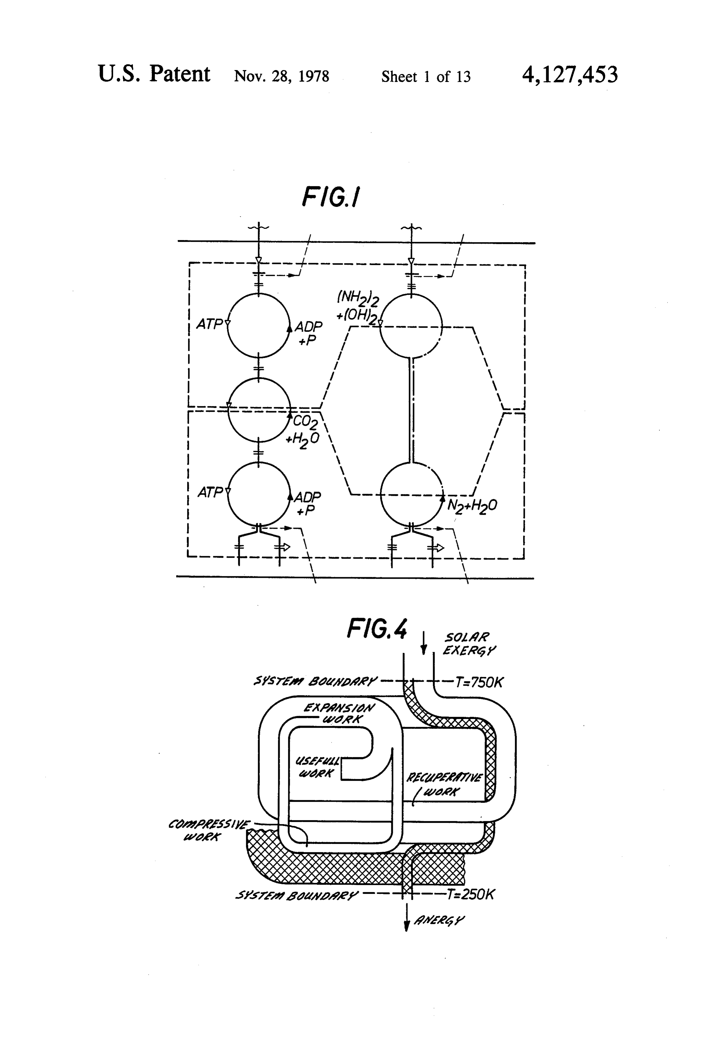
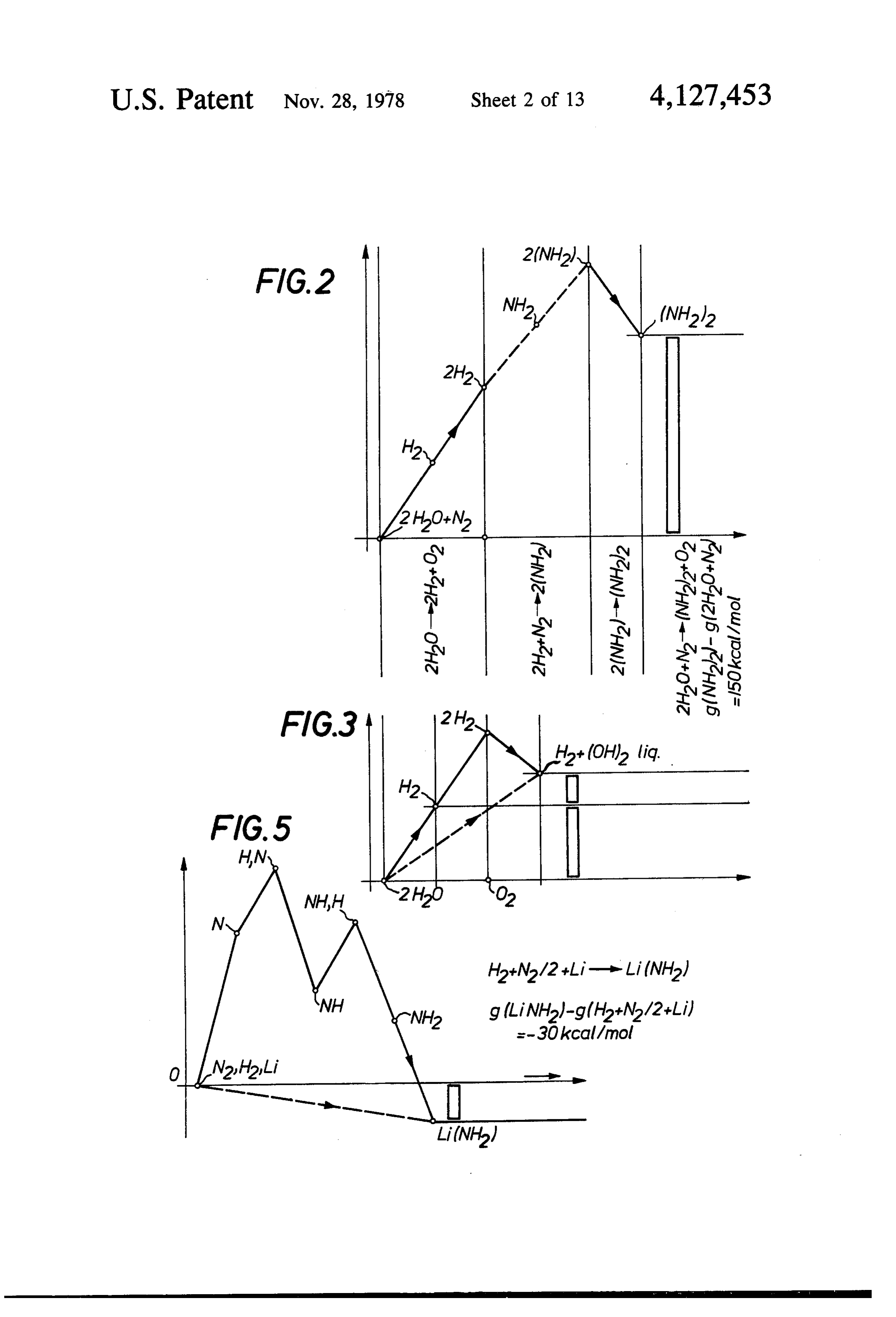
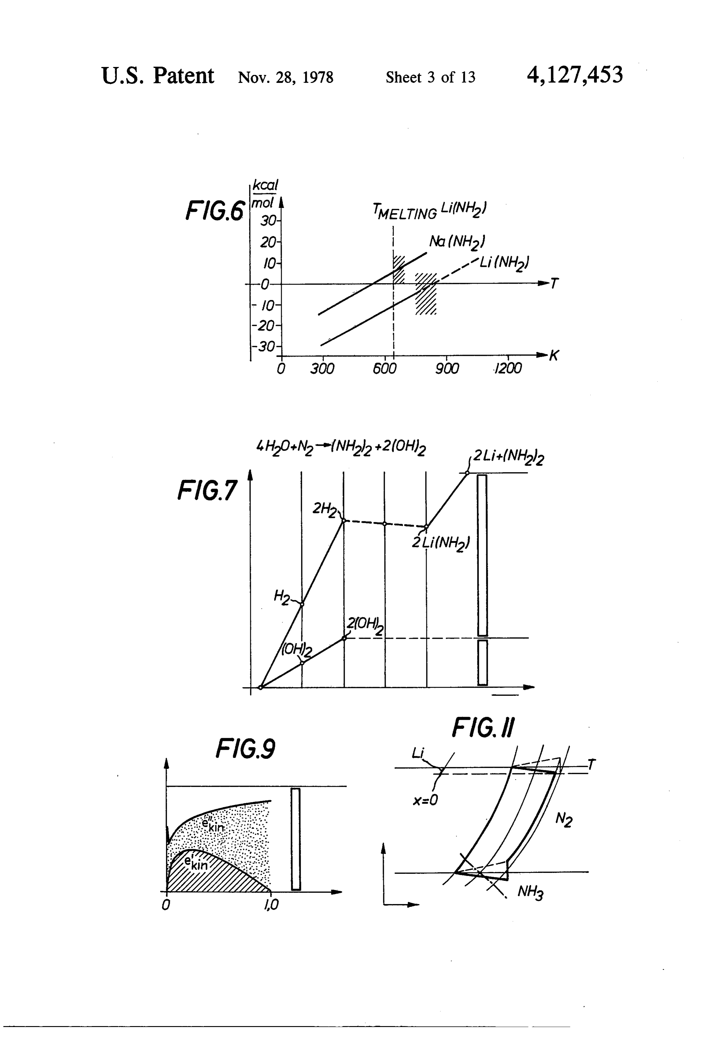
and H2 are introduced directly into the Li as passing FIGS. 1 to 7 describe some details of the scientific through the heat source and are made to react with Li basis of this invention, here in regard to the chemical with the aid of the finely dispersed Fe serving in this 65 process of exergy storage;
instance as catalyst. In a different part of the system, any While the FIGS. 9 to 11 describe some details of the (NH2) that has been produced must be evacuated from scientific basis of invention, here in regard to problems the free jet, passed through the space between the jet of physics of exergy storage;
Page 22
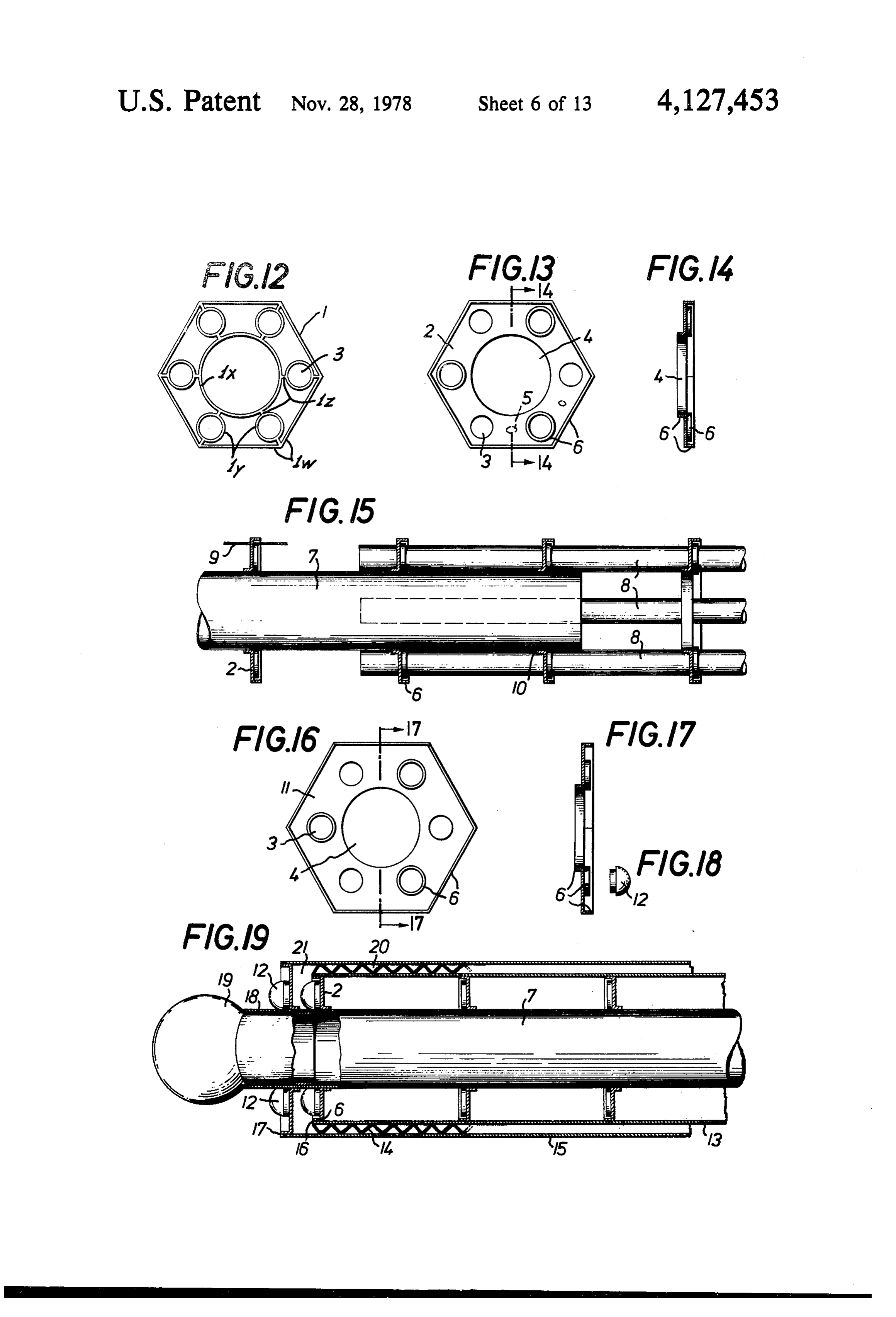
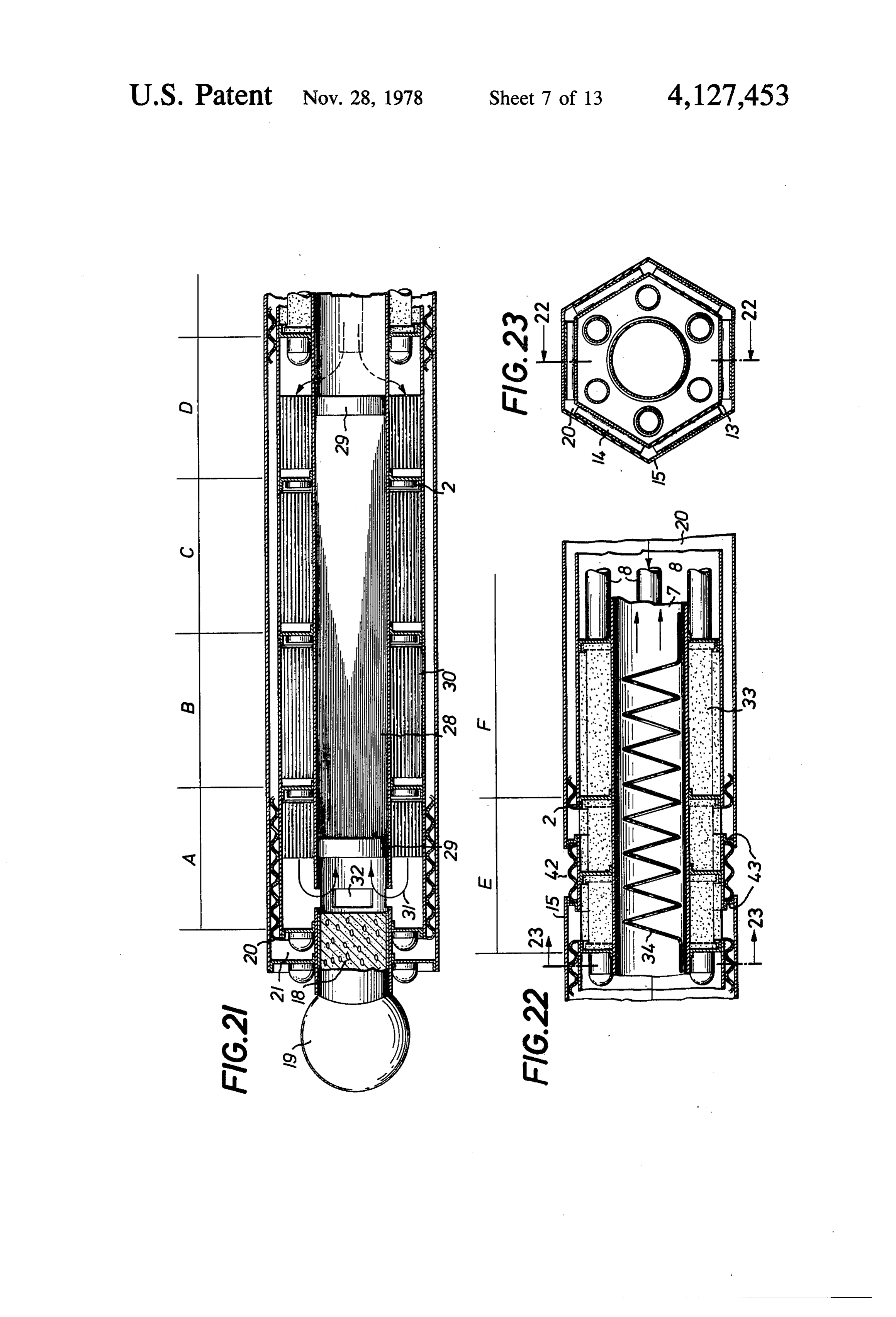
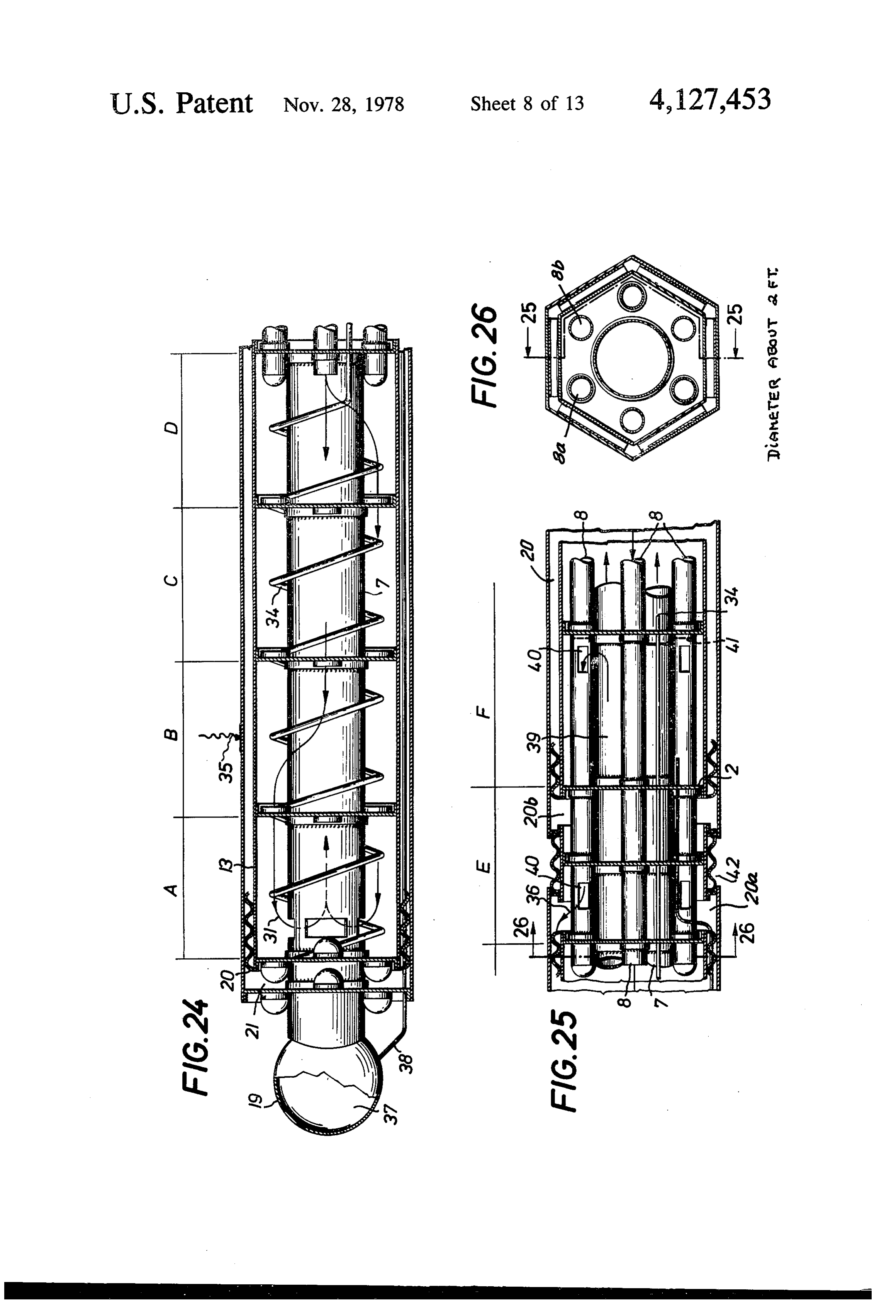
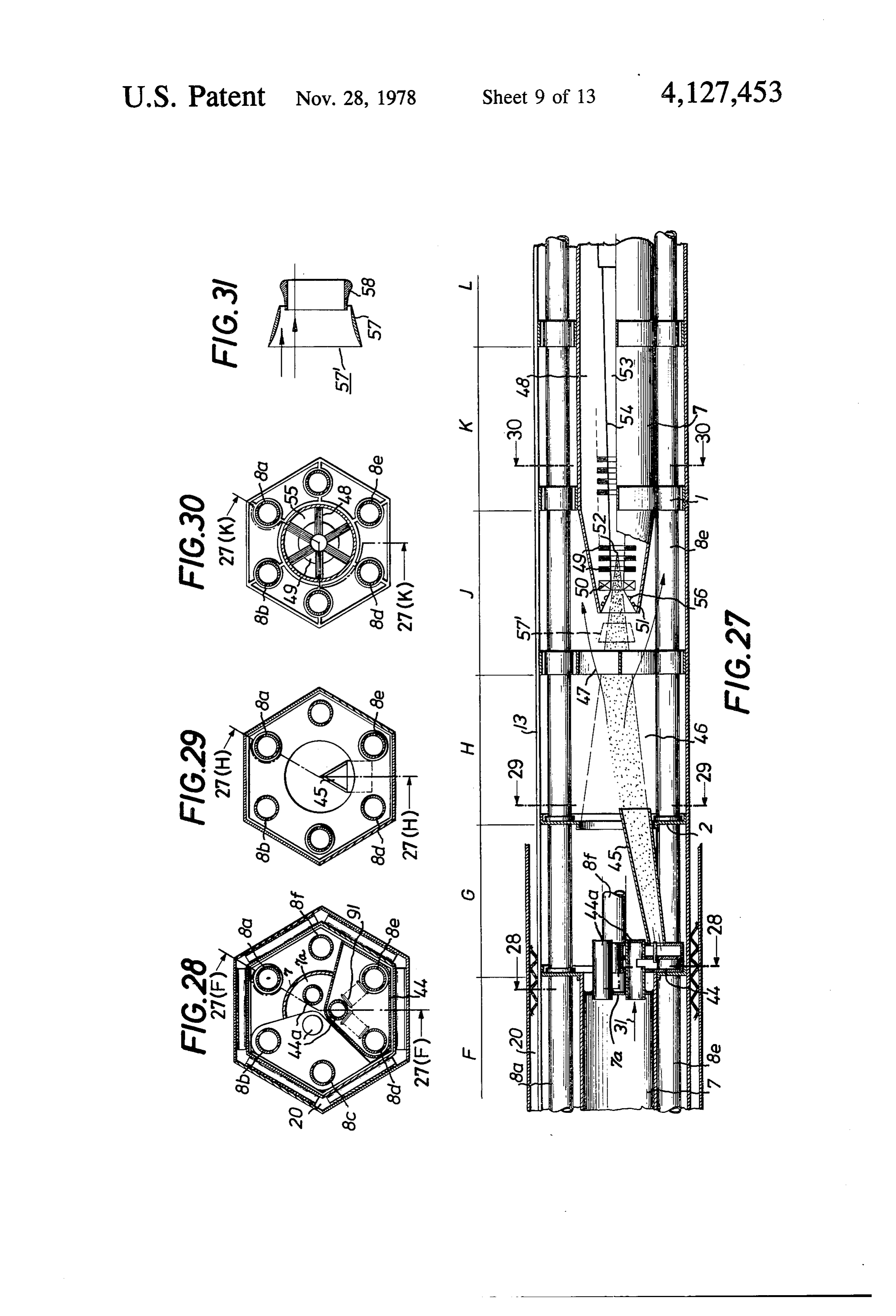
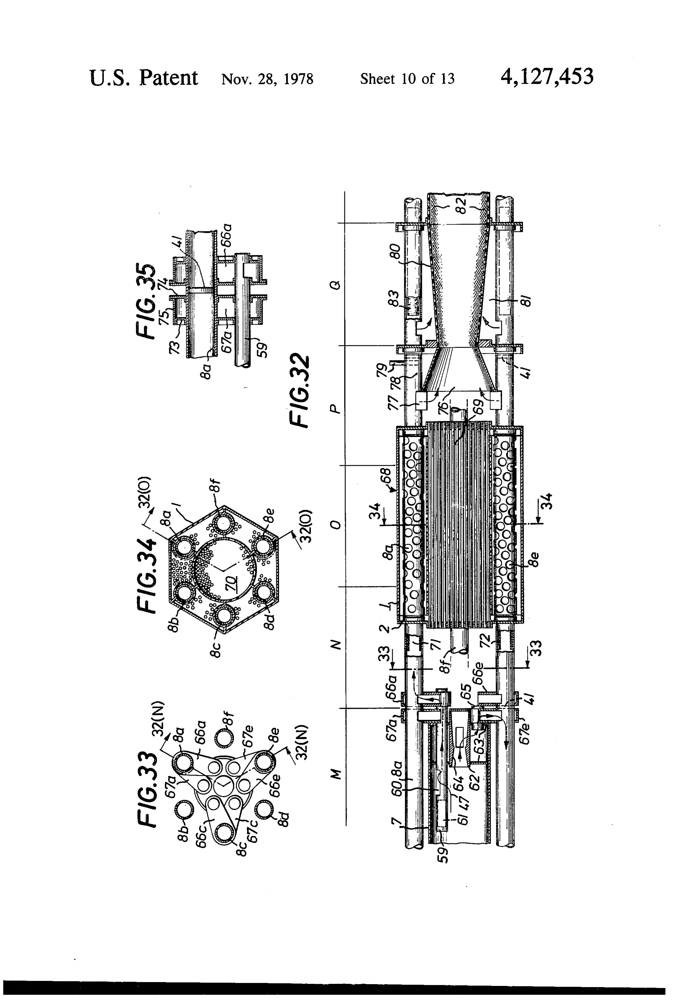
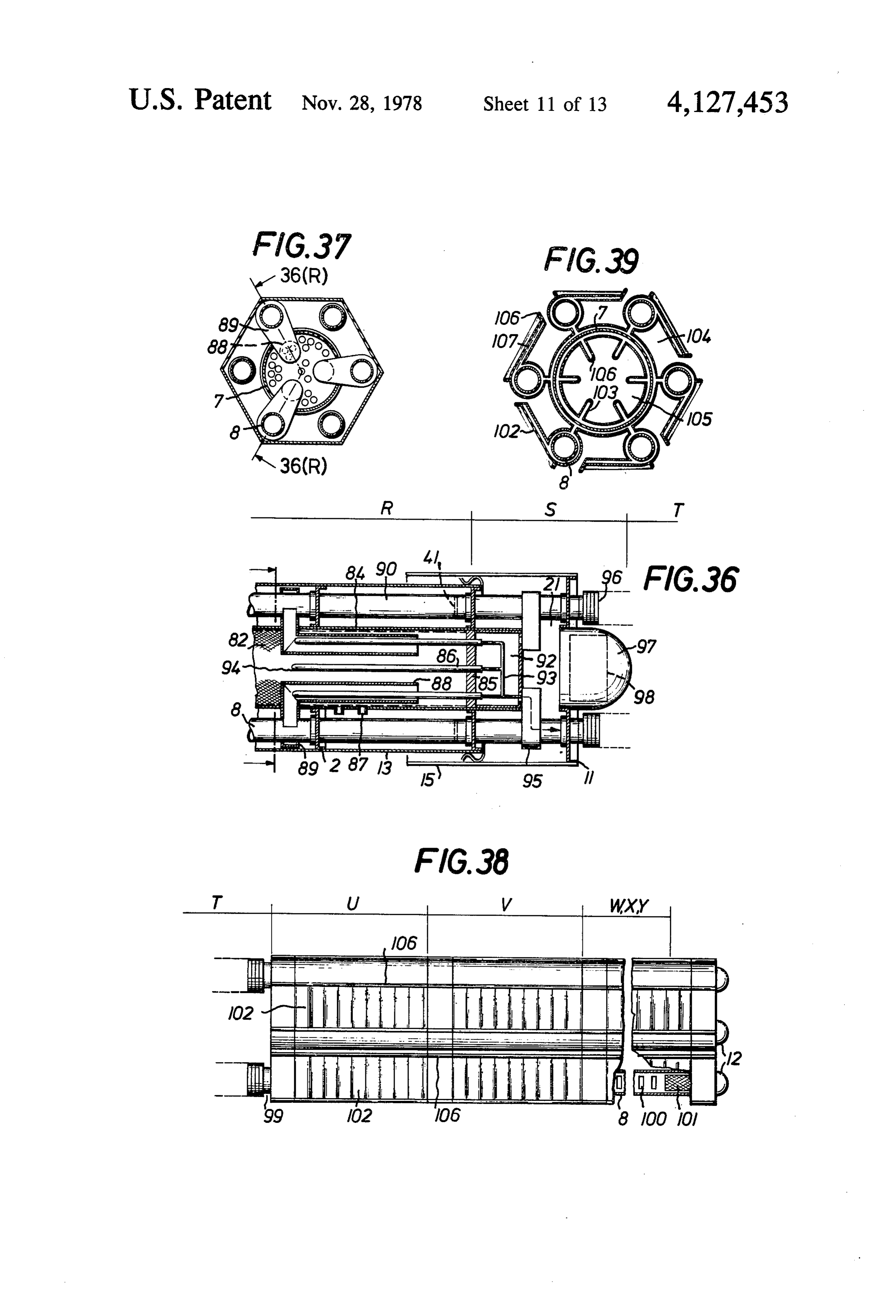
FIGS. 12 to 39 include the principal informations in FIG. 27 is a sectional longitudinal view of the com respect to the engineering design of the MHD-modules partments F, G...L of the MHD-module and continu of the exergy transformer system total, given by differ ing either FIG. 22 or FIG. 26;
ent sectional views and details of embodiments, FIGS. 28, 29 and 30 are correspondingly labelled whereby particularly longitudinal section views, in 5 sections taken from FIG. 27;
overlapping illustration, of FIGS. 24, 25, 27, 32, 36 and FIG. 32 is a drawing of details explaining the ring 38 show one module, and concatenated FIGS. 21, 22, shaped separator with a Coanda-lip for multiphase flow 27, 32, 36 and 38 show an alternative module. in FIG. 26;
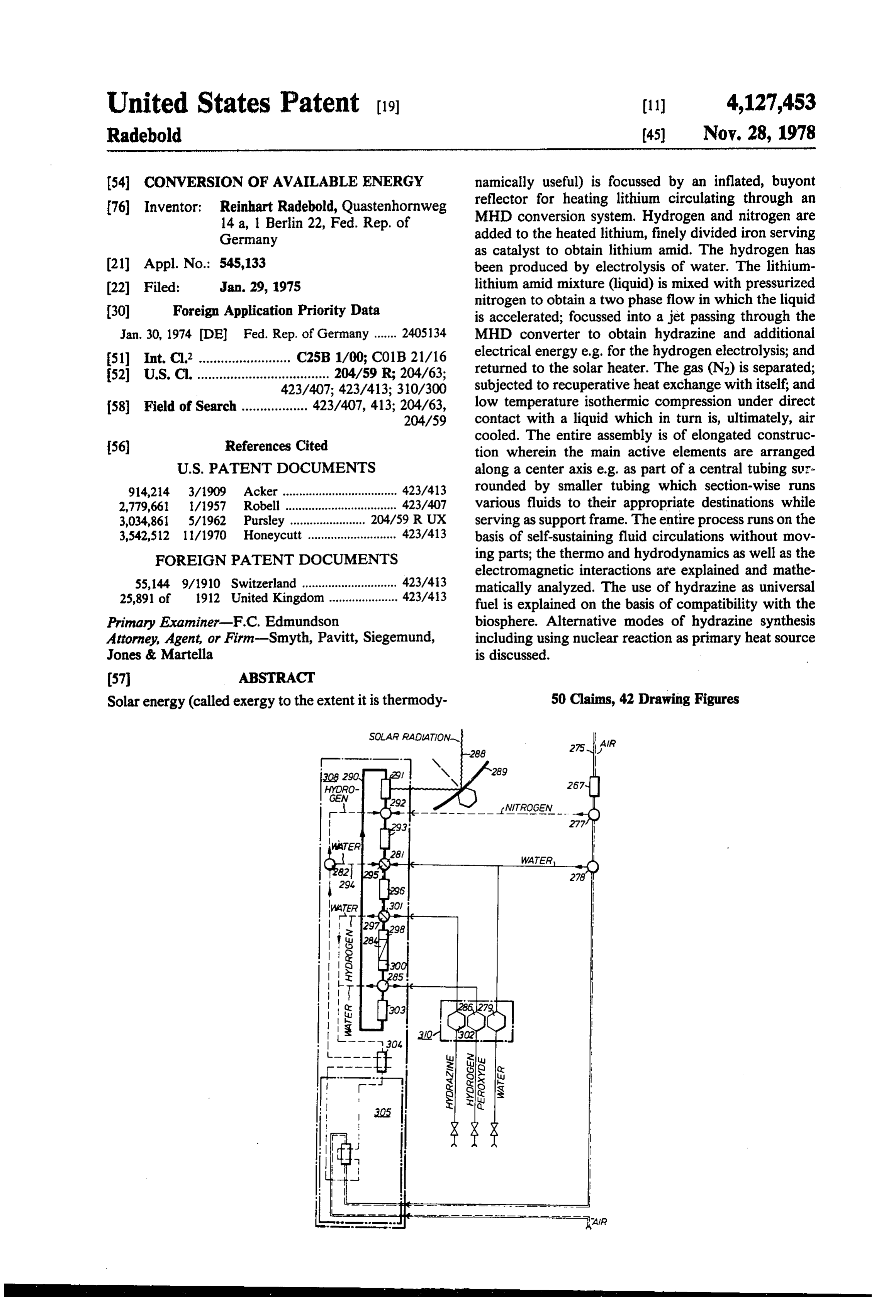
FIG. 1 is a demonstrative illustration for comparing FIG. 32 is a longitudinal section view of the compart the biological exergy transformations with future tech-10 ments M, N. . . Rof the MHD-module and continuing nical exergy transformations on solar basis due to this FIG. 27;
invention; FIG.33 and 34 are correspondingly indicated cross FIG. 2 is a graph showing the exergy required for the sections in FIG. 32;
synthesis of hydrazine, subdivided into the steps forma 15 FIG. 35 is a drawing of details of FIG. 32 explaining tion of H2, formation of amide and combination of am together; a transfer mains made from stamped sheets welded ides to di-amide; FIG. 36 is a longitudinal section view of the compart FIG.3 is a graph showing the exergy required for the production of hydrogen-peroxide, subdivided into the ments Q, R... U of the MHD-module and continuing
steps formation of H2 and formation of hydrogen-perox 20 FIG. 37 is a cross-section along lines 37,37 in FIG. 36; ide; FIG. 38 is a longitudinal section view of the compart FIG. 4 is an exergy-flux diagram of the isenthalpic ments S, T. . . Y of the MHD-module and continuing isobaric process in regard to the thermo-fluid-dynamic FIG. 36;
working fluid;
FIG. 5 is a graph showing the exergy required for the 25 FIG. 39 is a cross-section along lines 39.39 in FIG.38; FIG. 40 is a sectional radial view of a mirror made synthesis of Li-amide from elements using a catalyst;
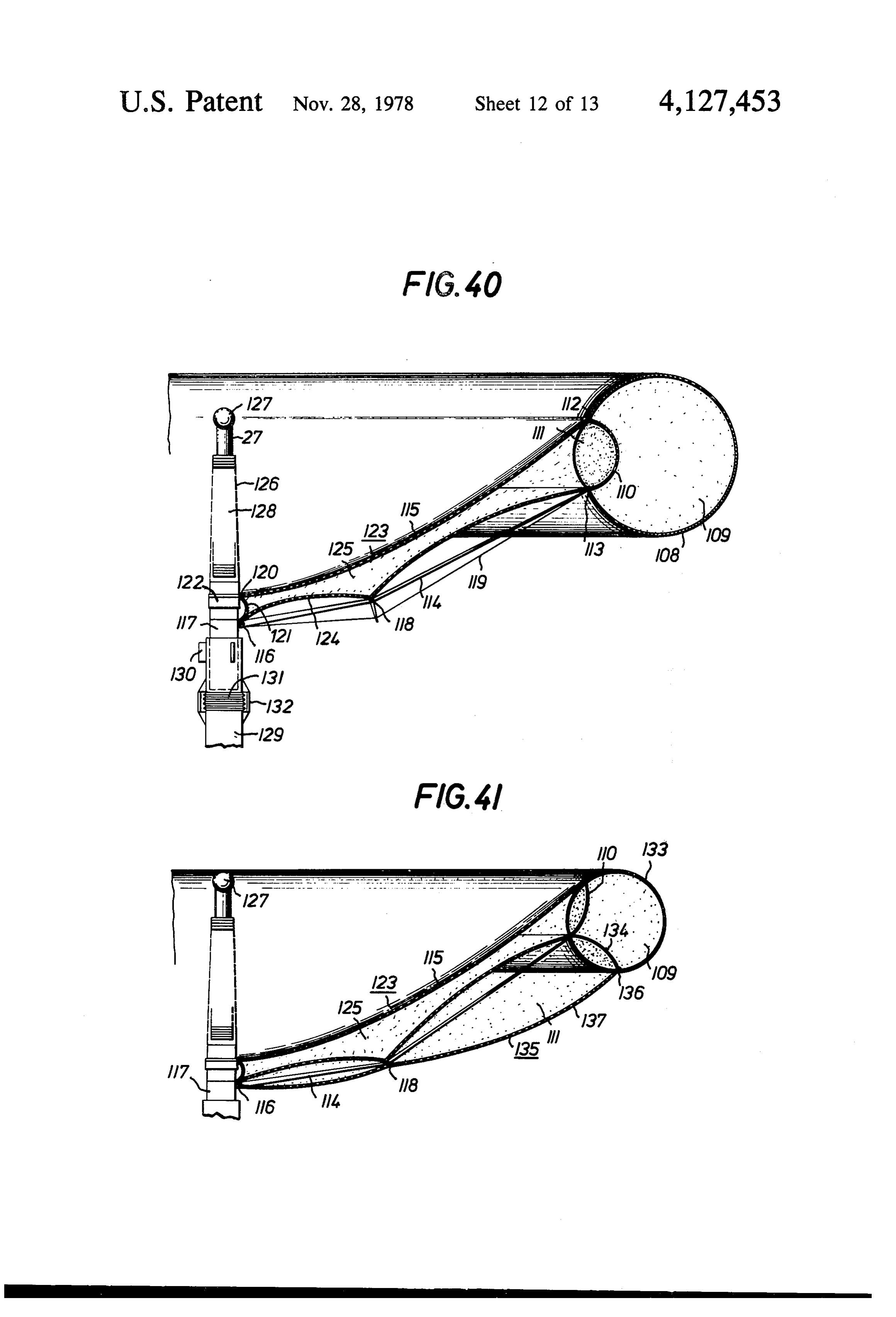
FIG. 6 is a graph in which free enthalpy for forma from foils and stabilized by pressure differences; tion of alkali-amides is plotted as a function of tempera mirror; 41
FIG.
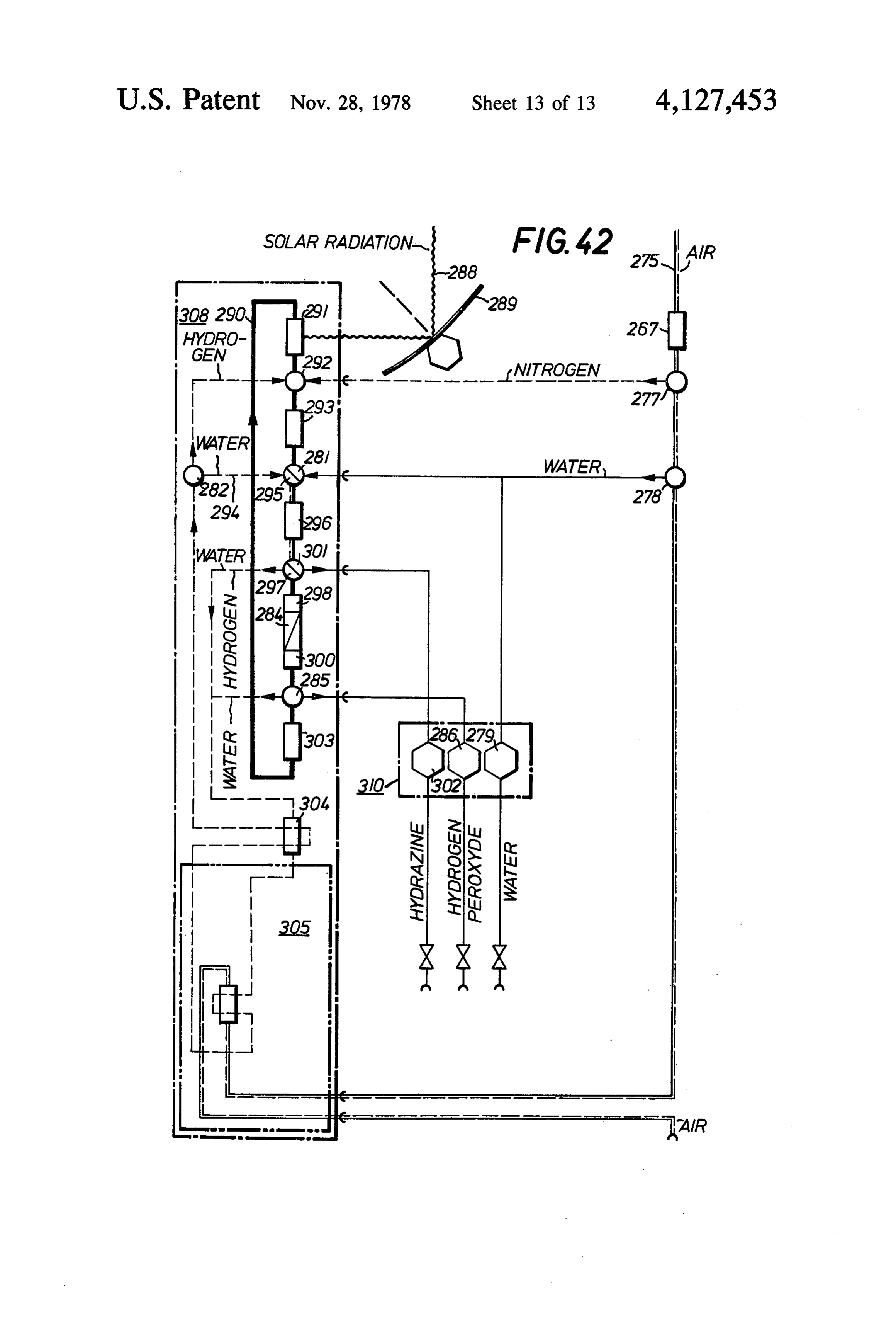
and is a sectional radial view of a different type of ture; FIG. 42 is a flow chart and system diagram, similar to FIG.7 is a graph in which the free enthalpy of forma. FIG.
tion of both hydrazine and hydrogen-peroxide is plotted in a single 8 but combining hydrazone and peroxide synthesis fluid flow system.
in units of process steps;
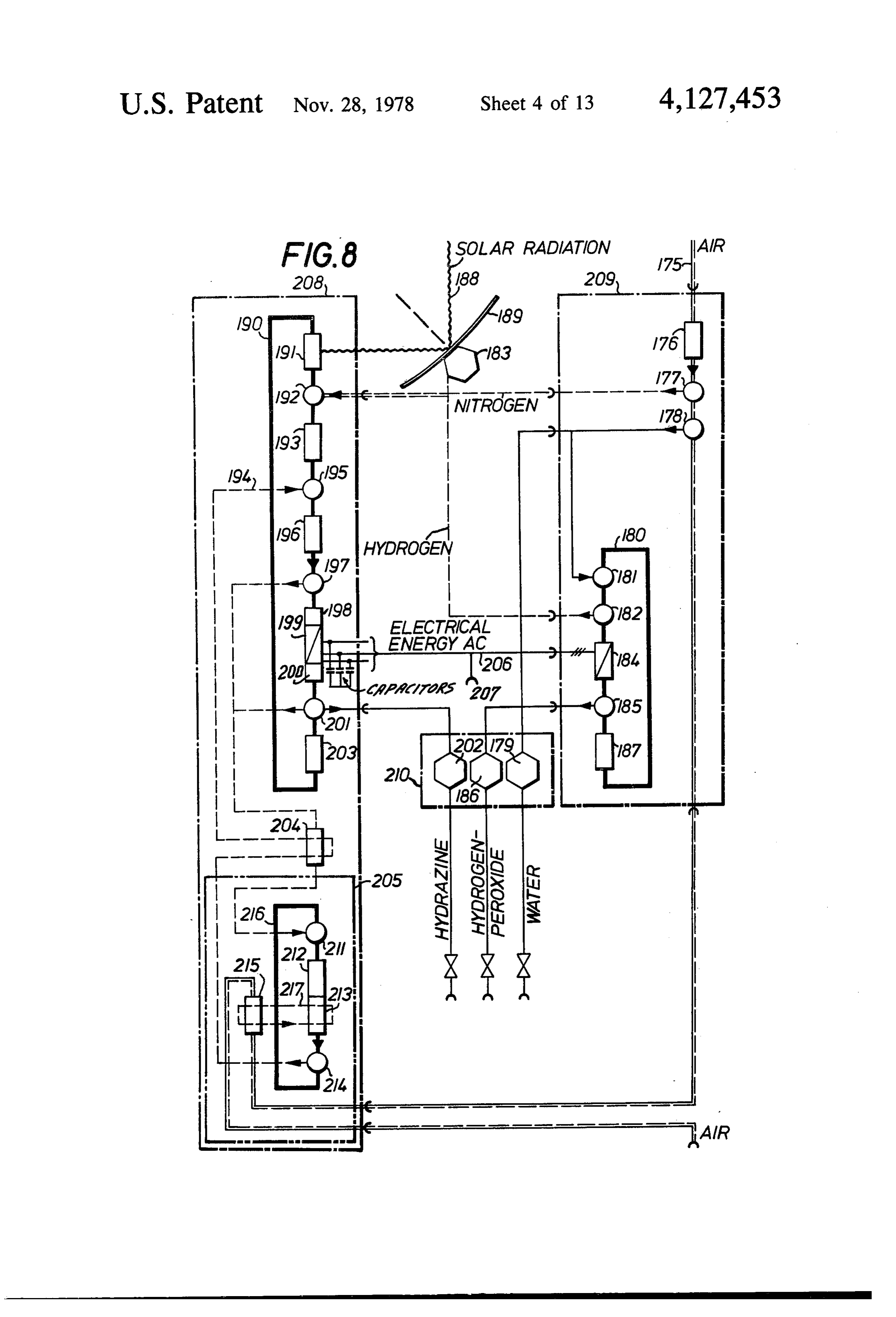
FIG. 8 is a flow and function diagram for the com OETALED DESCRIPTION OF THE plete process in accordance with the preferred embodi PREFERRED EMBODIMENT ment of practicing the invention in a system; 35 The preferred example of the exergy transformer FIG. 9 explains the transmission of exergy during system is based on utilization of solar energy; the solar acceleration of multi-phase fluids in the system of FIG. exergy is released by nuclear reactions on the sun, and
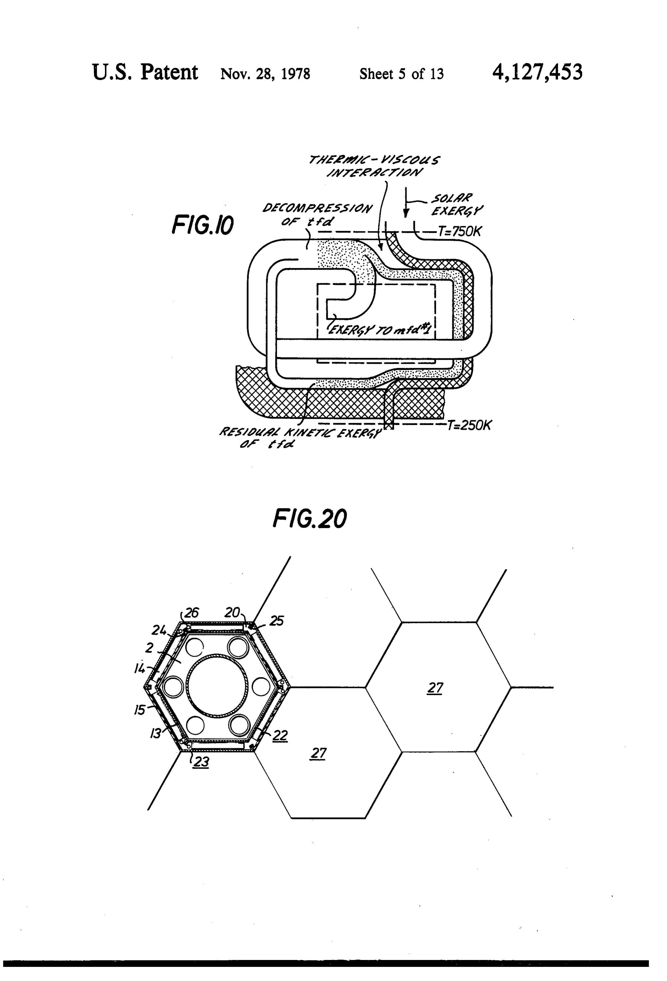
FIG. 10 is an exergy flux diagram of the isenthalpic stored in the form of free enthalpy of two metastable liquid compounds (NH2) and (OH)2, bearing in mind isobaric process in regard to the thermofluid-dynamic 40 that (OH)2 is generated only as a by-product of the working fluid of the MHD-system of the exergy trans generation of H2 which is needed for the (NH2)2 synthe former in accordance with the system of FIG. 8: SS
FIG. 11 presents the MHD-process of the exergy Both, the process of exergy transformation as well as transformer in a temperature-entropy diagram; . the design of the transformer system are determined by FIGS. 12, 13 and 14 are drawings of details of the 45 the physical quantities at the entrance or input and the MHD-module presenting the transverse and the longi exit or output of the transformer. Quantities at the en tudinal bulkheads or partitions; trance are the specific exergy of solar radiation spec FIG. 15 is a drawing of details of the MHD-module trally distributed as well as the flux density of radition; explaining the construction of the supporting skeleton; quantities at exit are the specific free enthalpies of the FIGS. 16, 17, 18 show details presenting an additional 50 two compounds synthesized in the transformer and the type of transverse bulkhead; ratio of both mass flows, respectively of exergy stored. FIG. 19 is a longitudinal section view for explaining The transformer yields additionally electrical energy the principle of manteling the supporting skeleton of an over and above the energy needed to maintain opera MHD-module; tion of the transformer system. FIG. 20 is a sectional horizontal view of a manifold of 55 The specific process envisioned here particularly as MHD-modules; far as the hydrazine synthesis is concerned, is to be seen FIG. 2 is longitudinal section view of the compart in that hydrazine is formed by an electrolytic process ments A through D of a MHD-module using nuclear specifically by forming (NH2)2 out of LiNH2. The en energy; ergy needed to sustain that process is taken ultimately FIG. 22 is a continuation section of additional com- 60 from the sun. The solar energy is used to obtain the partments of such a module; production of that electrical energy needed to sustain FIG. 23 is a cross-section along lines 23,23 in F.G.22; the electrolysis using lithium as or as part of a circulat FIG.24 is a longitudinal section view of the compart ing fluid system. The electrolysis will be produced ments A through D of a MHD-module using solar en within an MHD conversion process in which kinetic ergy; 65 energy of a fluid is converted into electrical energy, FIG. 25 is a continuation of the section view of FIG. including the energy to obtain the electrolysis. 24; The kinetic energy is the result of a two-phase pro FIG. 26 is a cross-section along lines 26.26 in FIG.25; cess in which solar exergy absorbed by a liquid phase is
Page 23
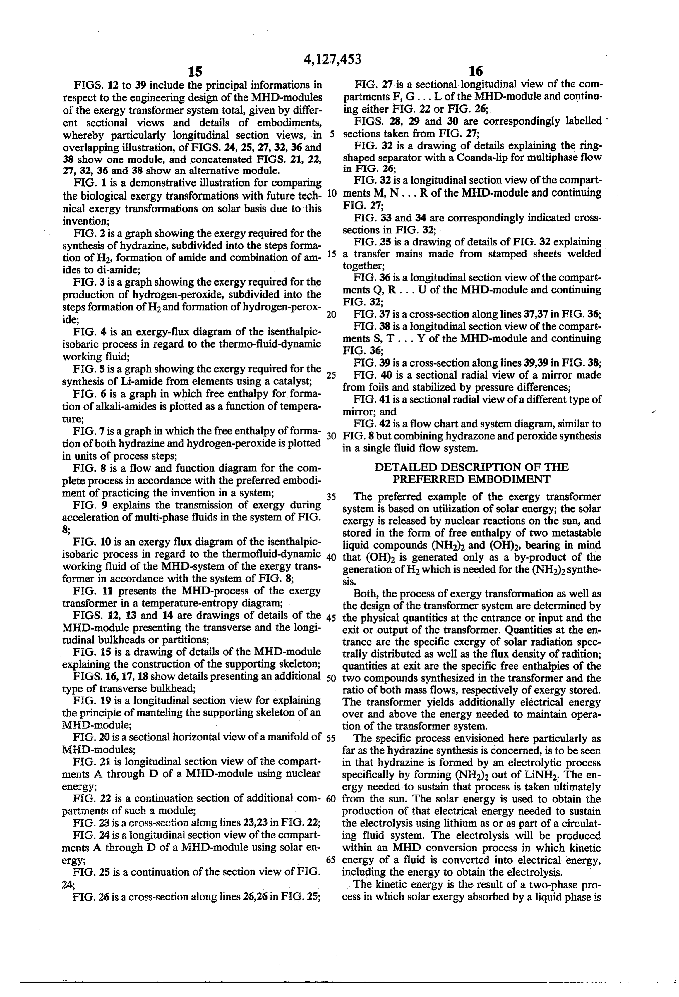
transferred to an isothermally expanding gas as it accel H -- O - (OH)2 erates the liquid phase, and the electrolysis is carried out in that liquid phase, while the movement of the liquid altogether:
phase is used to generate the magnetic field causing the 2 H2O - H -- (OH)2 electric field in the liquid phase to sustain electrolysis 5 therein. Liquid and gaseous phases complete separate The steps 1.1 and 2.1 are similar and O2 appears to be but temporarily linked circulations, whereby the liquid a rest product of synthesis 1 (through not to be pro phase absorbs the solar energy, heats the expanding duced directly), gaseous phase while being accelerated by it, serves as which both can while be
His a rest product of synthesis 2, combined according to step 2.2 to carrier for the electrolysis and returns. The gaseous 10 hydrogen-peroxide. The two synthesis can be coupled phase of the two-phase flow is alternated between low in an overall exergy transformer system performing the temperature compression and high temperature expan following steps:
sion with recuperative heat exchange inbetween.
Turning now to details of certain aspects of this basic SYNTHESIS 1 + 2 COUPLED process, the specific energy of radiation depends on its 5 wave length; it is continuously distributed over the 1) 4 HO -> 4 H2 + 2 O. 'H' spectrum between the limits of about A = 0.8.10 m in 2) 2 H2 + 2 O2 - 2 (O "peroxide" the infrared and of about A = 0.3.10m in the ultravio 3) 2 H2 + N - 2 (NH 'anide' let. The specific exergy es of radiation, therefore, covers 4) NH + Nii, -> (NH2)2 "di-anide'
altogether:
the range of 4H2O + N2 - 2 (OH)2 + (NH2)2
Herein, steps (1) and (2) are only listed separately, in if related to the unit mol of particle quantities. This reality free oxygen is not produced. The FIGS. 2 and 3 quantity is calculated from the equation 25 present the change of free enthalpy g of formation of (NH2)2 and H2 + (OH)2. Generally speaking, if the e = N h cA difference in enthalpie after and before the reaction is positive, the step is endergonic, because the reaction with N = 6.02.10.1/mol (Avogadro's constant), h = can take place only by supply of exergy; exergy can be 6.63.10-3 Ws2 (Planck's constant), c = 3.108 m/s 30 stored by this reaction, if the reaction can be reversed. (speed of light). The fluxdensity d of radiation is de If the enthalpie difference is negative, however, the step fined to be the exergy, which passes through a surface is exergonic, due to the release of exergy, and reaction unit, in normal direction within unit time, and is approx takes place spontaneously.
imately, without taking into consideration any addi A brief estimate will clarify the principles of opera tional absorption in the atmosphere; 35 tion of the exergy transformation: the formation of H according to step 1 of the coupled processes 1 + 2 needs the supply of specific exergy of at least 56.5 kcal/- mol = 235 kWs/mol; the formation of hydrazine re
The process of synthesizing (NH2)2 and (OH)2 can be quires explained, in principle, as being subdivided into the 40 exergyatofleast solar a specific exergy of 630 kWs/mol. If the radiation were used directly for a photo following step: synthesis of these compounds, only the ultraviolet radi SYNTHESIS 1 ation could be employed, while the remainder of solar spectrum could not be used; in addition, the different
(NH2)2 from H2O and N2) reactions needed in that case will be multiquanta pro 1.1: "Formation of H and O, from H2O' 45 CeSSes. .
The exergy conversion and transformation system as 2 HO-> 2 H2 + O. per this invention absorbs actually the total exergy of solar radiation it receives and transfers it as heat to an 1.2: "Addition of N2 to H2 to obtain amide' inert gas (N2). This gas is the thermo-fluid-dynamic 50 working fluid, ortfd for short, of the MHD process and
synthesis and is used thermodynamically to drive a 1.3: "Combination of two amides to di-amide" liquid phase whose resulting kinetic energy can be used in an MHD conversion process and which can sustain
NH2 + NH2--> (NH) an electrolytic process due to interaction with the mag 55 netic field it generates.
altogether: In order to capture sufficient exergy by absorption, it is deemed necessary to increase the fluxdensity of solar 2 HO + N2 - O2 + (NH2)2 radiation by a factor of about 1000, cooperating directly with an exergy absorbing surface at the entrance of the
SYNTHESIS 2 exergy transformer for the transfer of heat into the (OH)2 from H2O transformer. Therefore, the input portion of the exergy transformer will include a focussing reflector, described 2.1 : “Formation of H2 and O2 from H2O' by way of example with reference to FIGS. 40 and 41, see also FIG. 8.
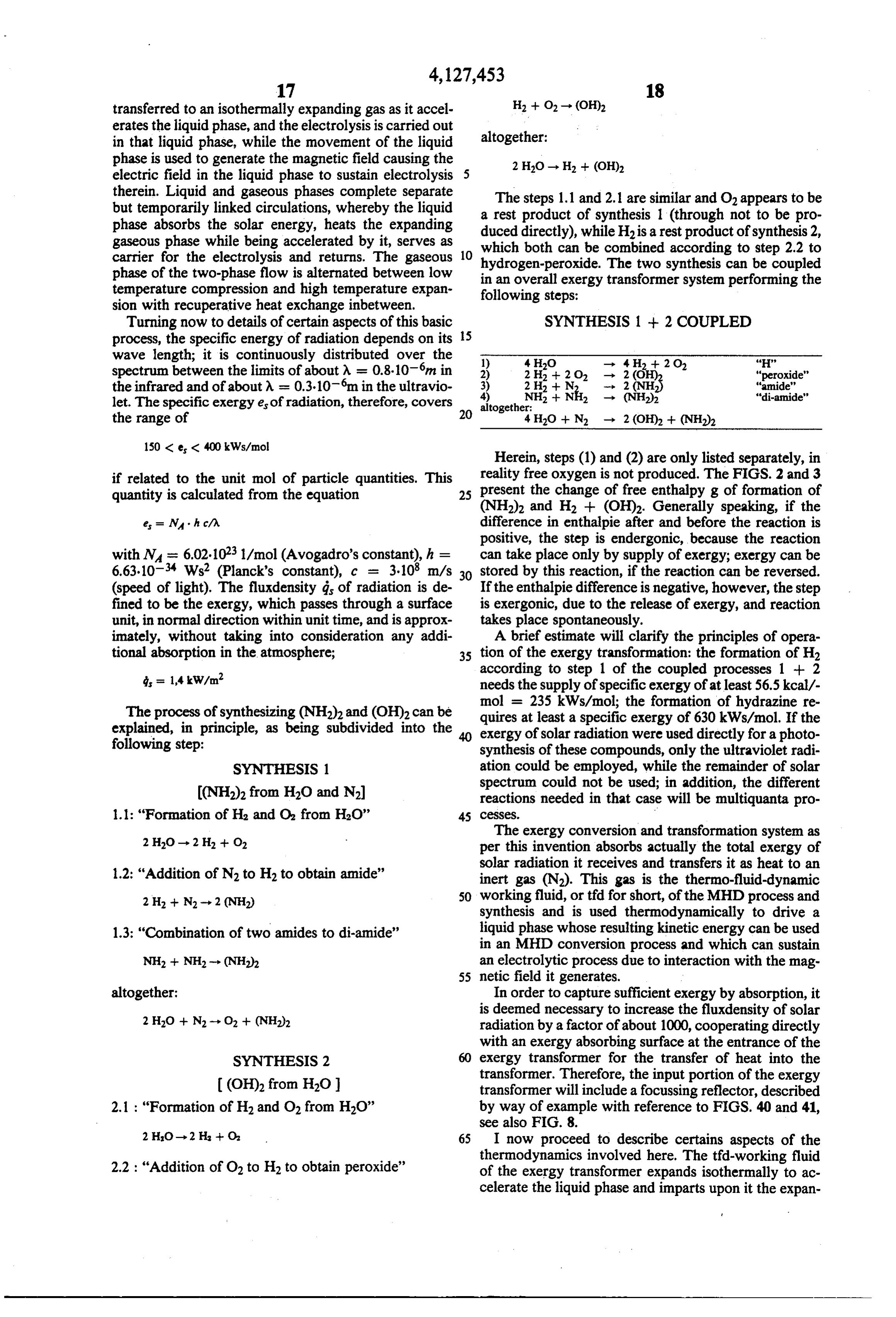
2 HO-2H -- O 65 I now proceed to describe certains aspects of the thermodynamics involved here. The tfd-working fluid 2.2 : "Addition of O2 to H2 to obtain peroxide' of the exergy transformer expands isothermally to ac celerate the liquid phase and imparts upon it the expan
Page 24
sion work as kinetic energy; by this the t?d working considered), the latter depending on the temperature fluid performs work to overcome internal forces, and ratio Tow/Tupper exclusively :
ultimately that work is used is the electrolytic process, conceivably even for both electrolytic processes. Con kin' . . . (8) versely the radiation as absorbed by the liquid phase itself, prior to that acceleration will replenish continu
ously the enthalpy of the gas that was converted into = C (9) work in the transformer. As a result, the enthalpy avail able (i.e. exergy of enthalpy) will not change during the To give an example: for Tre = 750K and for To = expansion and will be constant even at the end of expan 10 250 K is according to equation (8) m = mc = 0.666. sion. This enthalpic exergy must be withdrawn from the The maximum specific network is in this case accord gas (tfd fluid), which has expanded, before the gas will ing to (4) about 14 kWs/mol and is, therefore, lower by be recompressed for circulation within the transformer a factor of about 50 than that required for the different system, and transferred to the gas which is recom steps of synthesis. The net work of the thermo-fluid pressed already. Therefore, this exergy transfer will be 15 dynamic working fluid will be converted ultimately performed by a recuperative heat exchange between the into electrical energy, which is obtained by the intro decompressed gas and entering the heat exchanger at duction of a second working fluid, namely the liquid the lower pressure p = p, but at the upper tempera phase being accelerated by the expansion of the tfd gas ture T = Tier of process, and the gas that has already 20 and serving also as a fluid dynamic medium (mfd #1) been compressed again, and entering the heat exchanger that performs mechanical work in that an MHD con (again) now at the higher upper pressure p = pupper, but version process converts the kinetic energy of that mfd at the lower temperature T = T. #1 fluid into the electrical energy needed for the elec The process of the thermo-fluid-dynamic working trosynthesis. Moreover, the substance to be electrolyti fluid is determined by these two conditions for isenthal 25 cally decomposed must become a part of the liquidous pic expansion as well as for the introduction of recuper phase of the MHD working fluid, as will be discussed ative heat exchange. FIG. 4 shows the exergy flux dia shortly.
gram of this process. The specific work of expansion - The hydrazine (and peroxide) electrolysis requires a a performed by the t?id gas with a mass flow rate voltage of a few volts. Details of this MHD conversion ma, must be balance by the heat flux supplied Qin: 30 process and the generation of the necessary electrical energy will also be described below. Presently it should d = -hyd dep (1) be discussed what energy is actually needed for the electrolytic synthesis of hydrazine and peroxide and
The specific work is given by : what electrochemical reactions are involved. exp = R Tier in (2) 35 The specific work expended on an electric charge, after having traversed a voltage difference of n-volts is:
f = Pupper/Plow (pressure ratio of process), R = 8.3 ael =ney = n.1.6.10'Ws (10) Ws/mol K (gas constant of N). The specific work of compression is given by :
40 or, if one uses mols to define particle quantities, that
value all is given by n-Nev = 100 kWs/mol. The worka is the one needed to obtain the electrolytic pro
Compression should, therefore, take place at as low cess;MHD n is the voltage that will in fact produce that work. temperature Tow Turer as possible, in order to limit 45 The process is designed to furnish that value n; it is but a few volts.
the work to be supplied, for the difference of expansion and compression work is the net useful work provided theThe electrosynthesis of (NH)2 and (OH)2 by means of above mentioned four steps depends on the fact that by the process: there is a similarity in structure in these two compo - anet = - (aerp - 9amp) = R (Tupper - Tow) in nents, namely two groups or radicals are intercon f (4) 50 nected, OH and NH respectively. Moreover, the groups are chemically rather similar. In order to de
The requirement of recuperative heat exchange results velop the desired reactions and the means of obtaining in a limiting condition for the maximum of pressure them, the follow step by step analysis is helpful. ratio, because the available energy of gas which has to The OH groups and the NH2 groups both can be be transferred within the heat exchanger, cannot exceed 55 generated as negatively charged ions in that specifically the network of process : H2O as well as NH3 molecules can appear as hydrogen donors as well as hydrogen acceptors in accordance
(Tupper - T) 2 R (Tupper - Ti) in 7f (5) with the following two reactions, occurring of course in different carriers for solutions.
c = 39.1 Ws/molK (specific heat at constant pressure of N2), k = 1.4 (adiabatic exponent of N2) As a result, NH, + NH, e NH+ NH, (11b) the maximum pressure ratio in is :
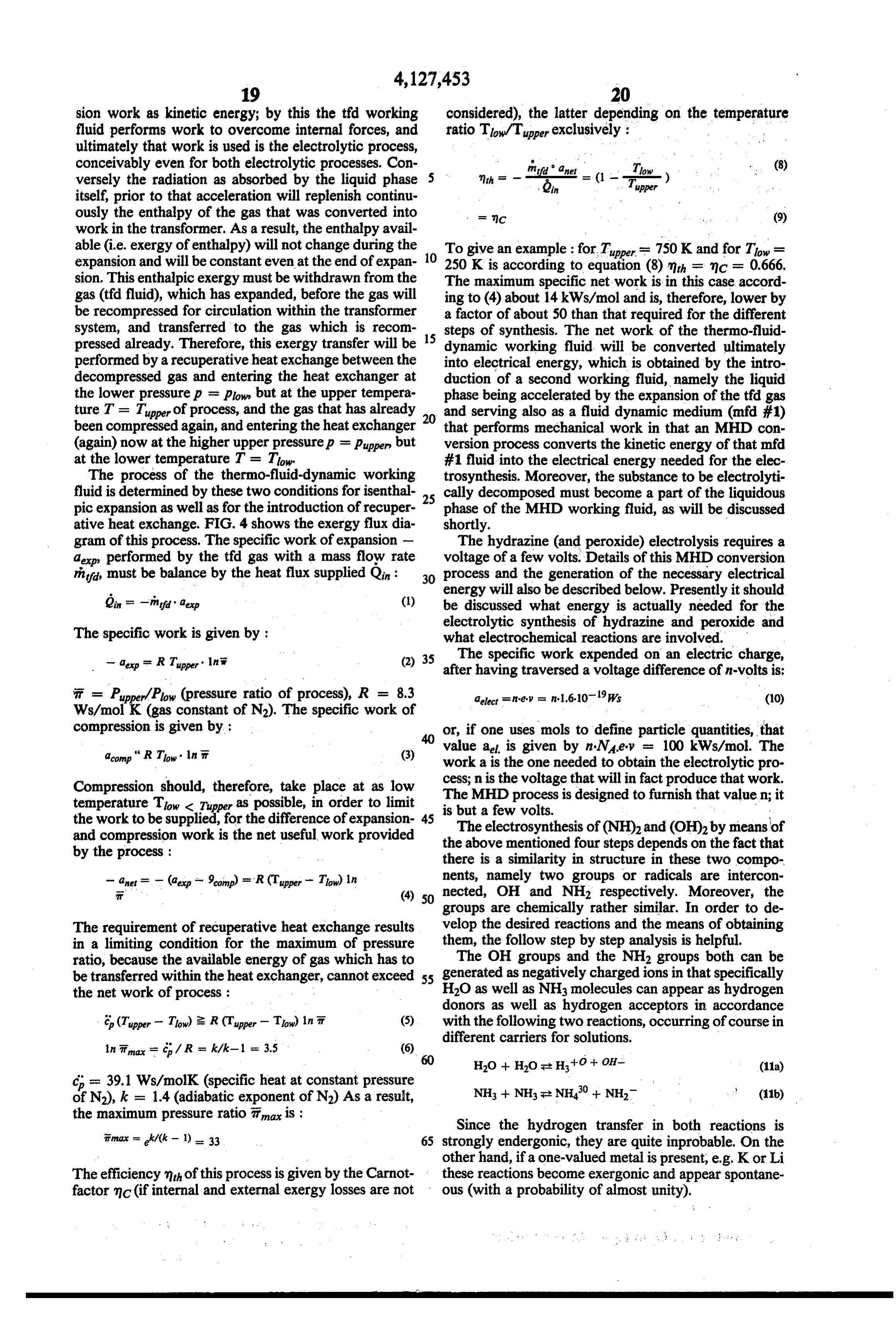
Since the hydrogen transfer in both reactions is timax = k/(k-1). 33 65 strongly endergonic, they are quite inprobable. On the other hand, ifa one-valued metal is present, e.g. K or Li
The efficiency of this process is given by the Carnot these reactions become exergonic and appear spontane factor nic (if internal and external exergy losses are not ous (with a probability of almost unity).
Page 25
energy produces a certain amount of electrical energy.
About 75% of that electrical energy is stored by means li3 + Li-. Htt - H/2 + Lit -- NH of the electrosynthesis of (OH)2 and H2, the remainder
of the electrical energy (25%) are used for the electroly
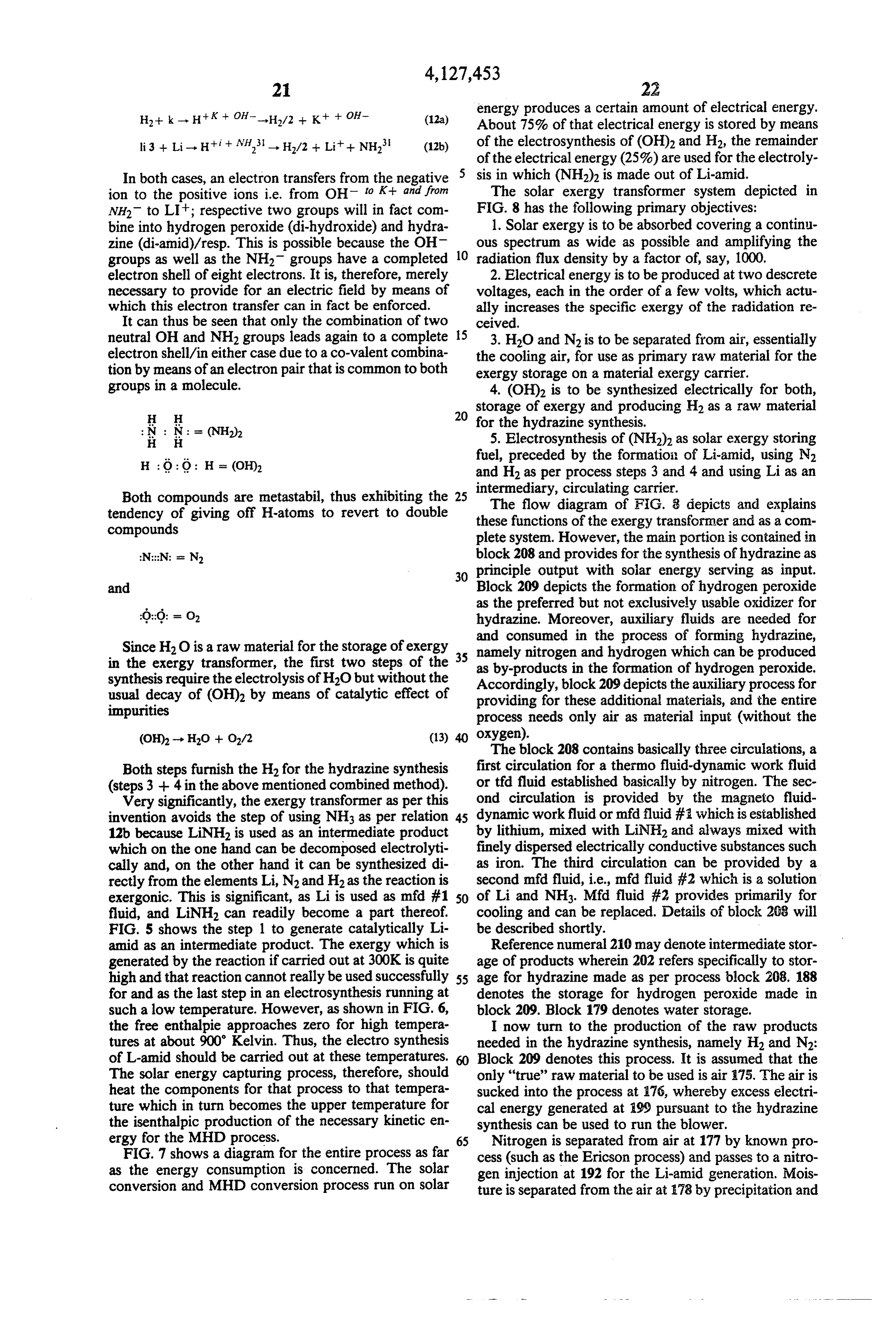
In both cases, an electron transfers from the negative sis in which (NH2) is made out of Li-amid. ion to the positive ions i.e. from OH to K+ and from The solar exergy transformer system depicted in NH2 to LI; respective two groups will in fact com FIG. 8 has the following primary objectives: bine into hydrogen peroxide (di-hydroxide) and hydra 1. Solar exergy is to be absorbed covering a continu zine (di-amid)/resp. This is possible because the OH ous spectrum as wide as possible and amplifying the groups as well as the NH2 groups have a completed 10 radiation flux density by a factor of, say, 1000. electron shell of eight electrons. It is, therefore, merely 2. Electrical energy is to be produced at two descrete necessary to provide for an electric field by means of voltages, each in the order of a few volts, which actu which this electron transfer can in fact be enforced. ally increases the specific exergy of the radidation re It can thus be seen that only the combination of two ceived.
neutral OH and NH2 groups leads again to a complete 5 3. H2O and N2 is to be separated from air, essentially electron shell/in either case due to a co-valent combina the cooling air, for use as primary raw material for the tion by means of an electron pair that is common to both exergy storage on a material exergy carrier. groups in a molecule. 4. (OH)2 is to be synthesized electrically for both,
storage of exergy and producing H2 as a raw material s for the hydrazine synthesis.
5. Electrosynthesis of (NH2) as solar exergy storing
fuel, preceded by the formation of Li-amid, using N2 and H2 as per process steps 3 and 4 and using Li as an
Both compounds are metastabil, thus exhibiting the 25 intermediary,
The flow circulating carrier.
diagram of FIG. 8 depicts and explains tendency of giving off H-atoms to revert to double these functions of the exergy transformer and as a com compounds plete system. However, the main portion is contained in block 208 and provides for the synthesis of hydrazine as 30 principle output with solar energy serving as input.
and Block 209 depicts the formation of hydrogen peroxide as the preferred but not exclusively usable oxidizer for hydrazine. Moreover, auxiliary fluids are needed for and consumed in the process of forming hydrazine,
Since H2O is a raw material for the storage of exergy 35 namely nitrogen and hydrogen which can be produced in the exergy transformer, the first two steps of the synthesis require the electrolysis of H2O but without the as by-products in the formation of hydrogen peroxide. Accordingly, block 209 depicts the auxiliary process for usual decay of (OH)2 by means of catalytic effect of providing for these additional materials, and the entire impurities process needs only air as material input (without the (OH)2 - HO -- O2/2 (13) 40 oxygen).
The block 208 contains basically three circulations, a
Both steps furnish the H2 for the hydrazine synthesis first circulation for a thermo fluid-dynamic work fluid (steps 3 + 4 in the above mentioned combined method). or tid fluid established basically by nitrogen. The sec Very significantly, the exergy transformer as per this ond circulation is provided by the magneto fluid invention avoids the step of using NH3 as per relation 45 dynamic workfluid or mfd fluid #: which is established 12b because LiNH2 is used as an intermediate product by lithium, mixed with LiNH2 and always mixed with which on the one hand can be decomposed electrolyti finely dispersed electrically conductive substances such cally and, on the other hand it can be synthesized di as iron. The third circulation can be provided by a rectly from the elements Li, N2 and H2 as the reaction is second mfd fluid, i.e., mfd fluid #2 which is a solution exergonic. This is significant, as Li is used as mfd #1 50 of Li and NH3. Mfd fluid #2 provides primarily for fluid, and LiNH can readily become a part thereof. cooling and can be replaced. Details of block 208 will FIG. 5 shows the step 1 to generate catalytically Li be described shortly.
amid as an intermediate product. The exergy which is Reference numeral 210 may denote intermediate stor generated by the reaction if carried out at 300K is quite age of products wherein 202 refers specifically to stor high and that reaction cannot really be used successfully 55 age for hydrazine made as per process block 208. 188 for and as the last step in an electrosynthesis running at denotes the storage for hydrogen peroxide made in such a low temperature. However, as shown in FIG. 6, block 209. Block 179 denotes water storage. the free enthalpie approaches zero for high tempera I now turn to the production of the raw products tures at about 900 Kelvin. Thus, the electro synthesis needed in the hydrazine synthesis, namely H2 and N2: of L-amid should be carried out at these temperatures. Block 209 denotes this process. It is assumed that the The solar energy capturing process, therefore, should only "true' raw material to be used is air i75. The air is heat the components for that process to that tempera sucked into the process at 76, whereby excess electri ture which in turn becomes the upper temperature for cal energy generated at 199 pursuant to the hydrazine the isenthalpic production of the necessary kinetic en synthesis can be used to run the blower. ergy for the MHD process. 65 Nitrogen is separated from air at 177 by known pro FIG. 7 shows a diagram for the entire process as far cess (such as the Ericson process) and passes to a nitro as the energy consumption is concerned. The Solar gen injection at 192 for the Li-amid generation. Mois conversion and MHD conversion process run on solar ture is separated from the air at 78 by precipitation and
Page 26
injected at 181 in a flow of a mfd fluid #3 circulating certain electric conductivity and ferromagnetic charac along a path 180 for an H2 producing electrolytic pro teristics. This second medium when moved in an exter cess. Excess water as separated may be stored and/or nal magnetic field interacts therewith electromagneti discharged at 179. cally by means of the so called Lorentz-force. These Hydrogen is separated from circulation 180 at 182 i.e. two media can additionally interact fluid mechanically it sucked out of the system for injection at a point 192 by operation of their viscosity, for one fluid drags the into the flow of mfd fluid #1 of the hydrazine synthesis other. Together they constitute the two phase MHD process 208. work fluid wherein the tfd fluid is the gaseous phase and An MHD conversion process with hydrogen perox the mfd #1 fluid is the non-gaseous (predominantly ide synthesis takes place at 184 whereby electrical en 10 liquidous) phase.
ergy for the electrolytic process is furnished by the An MHD process operates as follows: the tfd work solar MHD conversion system 208 via line 206. The fluid (gas) performs work when expanding, that work is process 184 therefore, runs as MHD motor under elec not expended against external forces but on the mfd #1 trolytic generation of H2 and (OH)2. The peroxide is work medium. Rather than moving turbine blades, pis extracted from the circulation at 185 by evaporation 15 tons or the like, work is expended on the basis of local (using e.g. excess heat from unit 208) and after conden imbalances, and specifically for the case of viscous in sation of the (OH)2 will pass for storage to 186. teraction work is performed by one medium on the FIG. 8 is actually drawn for illustrating functional other by operation of speed differentials and by the separation; the physical H2 separation i.e. the outflow of tendency to equalize such speed differentials as between hydrogen as a gas from the mfd ar3 fluid occurs right in 20 the two media. The mfd work fluid works against exter and from the conveter 184, so that 182 should actually nal forces, but not mechanical ones with varying system be superimposed upon 184. The situation is different, boundaries; rather the accelerated mfd #1 liquid works however, as to (OH)2. This perioxide is flushed out of against a retarding, outer magnetic field (across rigid the converter 184 and rapid physical separation from mechanical boundaries) which field in turn results from the H2 is essential, because otherwise (OH)2 will sepa 25 the movement of the electrically conductive liquid adja rate again into H2O and O2. The (OH)2 separation from cent energizing coils.
the mfd #3 is liquid at point 185 is carried out by evapo There is a certain lack in consistency in the known ration. MHD processes, namely that the compressing work The mfd fluid #3 with hydrogen passes through a performed on the t?id gas is carried out by means of prime mover 187 for sustaining the circulation (that 30 compressors having mechanically movable parts and may be a MHD pump) to complete the circulation. system boundaries. The novel process avoids this ap The fluid circulating through path 180 is a watery proach.
solution of potassium hydroxide. The MHD motor 184 Proceeding now to details of the hydrazine synthesis sets up a circular electric field in that solution. Specifi as outlined in FIG, 8, solar radiation 188 is collected by cally, the coil system in the converter 184 is excited by 35 a reflector 189 and focussed for absorption and heating electrical energy extracted from the hydrazine genera at 19 of the mfd fluid #1 which is lithium mixed with tor and solar energy converter 208. The watery solution finely divided Fe and moves in a circulation flow path of KOH with finely dispersed iron interacts with the 190. The heating process 191 may be carried out via a field generated with a slip S >O as between phase and separate circulation of sodium, the latter absorbing ther liquid velocity to originate toroidal current which are mal energy more readily and heating the lithium to a ultimately instrumental in the generation of the electrol temperature in excess of about 750 Kelvin. Nitrogen ysis. The Reynolds number (see definition below) is low and hydrogen are injected into the mfd #1 fluid at 192 due to the low electrical conductivity of H2O and the to obtain LiNH2 in 193 by catalytic reaction, the Fe interaction is rather weak. particles serving as catalyst and at a sufficiently high The negative OH ions and positive potassium ions 45 temperature. The functions 191,192, and 193 are carried sustain the current flow through the mfd liquid as a out in compartments A to D of FIG. 24. result of the electric field set up in KOH + H2O liquid The tifd working fluid (gas - N2) is mixed with the nfd as pumped through unit 184. Electron transfer results in #1 fluid at 195. The tfd gas circulates along a separate the generation of electrically neutral potassium as well path 94, but the mfd fluid #1 circulation as well as the as in the formation of (OH)2. The metallic potassium SO tfd fluid circulation are temporarily combined at that combines with the water to form (i.e. to restore) KOH point 195. The tifd fluid is pressurized at that point and with the result of formation of H2. upon mixing with the mfd fluid assumes its temperature, It should be noted, that the finely divided iron parti (compartment G in FIG. 27).
cles serve as principle electron conductors within the The combined fluids constitute a two phase flow, circular electric field set up in the liquidous mfd #3, so 55 whereby the mfd fluid #1 is predominantly the liquid that throughout current conduction is carried out pre phase and the tfd field is the gaseous phase. The gaseous dominantly by electron flow within the iron particles phase is decompressed isothermally at 96 so that a and through ion flow inbetween the particles bearing in portion of its enthalpie is converted into kinetic energy mind that the external energization is an alternating which in turn is imparted upon the droplets of the liquid field and the passing solution of KOH, water and (OH)2 mfd phase. The decompressed tifd fluid is separated will not undergo electron exchange with the electrodes from the nfd #1 fluid at 197, and the mfd #1 fluid is so that (OH)2 will not separate again into H2 and O2. focussed at 198. In reality, the focussing of the liquid The primary function of the exergy transformer 208 is phase is part of the separation from the gaseous phase - to convert specific exergy of the thermo fluid dynamic tfd fluid, N2 (compartment J of FIG. 27). The focussed working medium (tfd) into electrical energy under utili 65 liquid continues as a free flowing liquid jet riding on a zation of the liquidous magneto-fluid-dynamic work gaseous cushion and being subjected to an MHD con medium (mfd #1) which is basically a liquidous metal version process 199. In particular, the jet passes through and which includes finely divided iron so as to assume a a self-exciting coilcapacitor system, connected electri
Page 27
cally analogous to an asynchronous motor with capaci exerted by the t?id gas upon the two liquids whenever tor load for self-excitation. The interaction of the fast being mixed or combined therewith. The tfd gas does moving conductive-ferromagnetic jet with coils pro not have any access to any heat exchange with the duces a travelling magnetic field and interaction of the environment, except through the mfd #1 and #2 fluids. latter with the jet on the basis of the Maxwell equation 5 The interaction between the t?id gas and the two mfd curl E -- B = O produces an electric field so that the fluids (liquids) is predominantly but not exclusively LiNH2 in the jet is subjected to electrolysis. The iron based on viscosity. Rather, a generalized thermody particles serve as bipolar electrodes in the electrolytic namic force is effective being in the nature of a tempera process which sustain a current flow in the liquidous jet ture difference between the t?id gas and either of the mfd as a whole. Any electrical energy not consumed in the 10 liquids. This temperature differential enforces the heat electrolysis is externally available at 206, 207, driving, flow needed respectively for isenthalpic decompression for example, the MHD converter 184 in which the and compression.
water electrolysis takes place as outlined above. In particular, the mfcd fluids both serve additionally as Following the electrolysis the mfd #1 fluid is passed heat transfer and storage media. The mfd #1 liquid through an emergency jet spoiler 200 (jet shut off) and 15 stores solar energy and heats the tfd gas upon mixing block 201 represents the hydrazine separation from the and during decompression thereof. The mfd #2 fluid lithium, the residual LiNH2 and the iron particles. ensures low temperature isothermic recompression of The liquid jet is captured and recompressed at 203 the tifd gas. This function dominates as to mfcd #2, a (diffusor action), so that it can be returned via circula MHD pump keeps only the circulation going for that tion 190 to the zone of heating (191) completing the 20 liquid. The mass flow is lower by about a factor of 50 as path for Li and Fe, including residual LiNH3. Please compared with mfd #1 due to evaporative cooling of note also here, that the functionally separated steps 200, that mfcd #2 fluid.
201, 203 are realized in a combined structure (compart As a consequence, the technical system does not only ment M - FIG. 32). have rigid system boundary but the size of the system The decompressed gaseous t?id fluid was separated 25 boundaries have no influence on the process and work from the two phase flow at 197 and passes through a performed by the tfd work medium. In either case, t?id recuperative heat exchanger 204 in which it gives off and mfd fluids mix almost homogenially so that very thermal exergy to the tfol gas as leaving an isothermal large surface areas are available for the heat transfer, compression stage 205. A recuperative heat exchanger and the average depth of heat penetration is very very is shown in FIG. 32, compartment O. 30 small, so that this transfer occurs almost instantaneously The cooled t?id fluid enters 205 and is mixed with a on contact and mixing of the fluids. second mfd (or mfd #2) fluid at 211, to undergo heat As stated above, mfd #1 is a solution of Li and exchange so that the subsequent compression of the tfd LiNH2, the latter being in effect an intermediate prod fluid, box. 212, is carried out under isenthalpic condi uct for the synthesis of (NH2)2 from N2 and H2. The tions (compartment Q in FIG. 32). The mfd #2 fluid is 35 heat capacity and thermal conductivity of this solution condensed at 213 and separated from the tifd fluid (N2) (which includes some iron particles), permits full utili at 214 from which it is returned to the recuperative heat zation of the concentration of solar flux density by exchanger to receive thermal energy from the tfd fluid means of reflector 189 up to 125 W/cm2. The mfd #2 before the latter is recompressed. The pressurized and fluid is fully analogous thereto and tuned to a lower reheated t?id fluid is now returned to point 195 for mix operating temperature of, in cases, T = 250 K. It is a ing with the mfd fluid. About 10% of the pressure is solution of Li and HNH2 having a high electric conduc needed to sustain the return flow of the t?id gas to the tivity even at such low temperatures. Moreover, an mixing point 195. LiNH2 residue (from mfd #1) that may have been car The mfd #2 fluid following separation from the t?id ried over by the tfd gas to the mfd #2 liquid, can go into fluid is returned to mixing point 211. The condensation 45 solution to permit chemical regeneration, recovery and of the mfd #2 fluid as per function box 213 is actually return to the mfd #1 fluid. Mg and Ca are suitable part of the separation of function box 214 as far as im reactants to separate the LiNH2 from the mfd #2 fluid. plementation is concerned (compartment Rin FIG. 36). Before describing construction and layout of the The condensation is the result of heat exchange with a MHD system 208 in greater detail, I refer to an impor fluid in function box 213 circulating along path 217. 50 tant feature of this system, namely the reflector which is That heat exchange fluid is cooled by ambient air (box used for focussing the solar radiation. The radiation 215), whose flow is indicated by 216. density must be increased by about a factor of 1000. A FIG. 8 demonstrates the central position of the t?id rigid reflector may prove to be impractical and expen work fluid and the interaction of it with the two fluids sive. Moreover, it is advisable to provide a reflector mfd #1 and mfd #2. These interactions are limited in 55 which is in fact buyontly supported. Such a feature time and space and concern exclusively isothermic and facilitates the orientation of the mirror including fol isenthalpic processes. One is the isothermic decompres lowing the sun and a buyont construction may even sion of the tifd fluid in 196 under acceleration of the mfcd permit the mirror with centrally disposed MHD trans #1 liquid and carried out at the upper working tempera formation unit to be positioned at some distance from ture T = t the other process is the isothermic com 60 ground.
pression in 212 at the lower working temperature, T = FIG. 40 shows a modular MHD system (= 208) T, with mfd #2 serving as coolant, while being at shown as an elongated tube 27. One of the units shown least in parts caused to circulate by the decelerating t?id in detail in FIGS. 24 through 39 may be contained in or gas as it is being compressed. constitute module 27, or a cluster thereof will be ar The gaseous t?d work medium circulates through the 65 ranged as shown in FIG. 21 and may be contained in system without receiving or expending any work via unit 27. The front portion of each such module (com movable system boundaries. Both liquidous media, mfd partments A to D of FIG. 24, or portion 191 of FIG. 1) #1 and mfd #2 are driven by means of dragging forces is contained in the focus 127 established either by the
Page 28
exposed outer skins 15 of the modules or by a "black" tensioning cushion 135 rather than the cable 119 of FIG. absorber covering that skin. The modules or tube 27 is 40 are provided. Thus, one does not need mechanical held via tube 126 for support and protection. Reference operation of such cable.
numeral 128 refers to the air gaps through which air can The cushion 123 is deployed by inflating cushion 135 enter into heat exchange at the low temperature side of 5 through injection of hydrogen 111. Since that cushion the modules (see compartments S through Y, FIG. 38). adds buyoncy, bead-hose 13 can be made smaller in The reflector is established by a reflecting foil 115 deed. The tensioning cushion 135 is established on its which constitutes the inner surface of the concave mir upper side by lower foil 124 of the reflector cushion, ror as well as the top foil of a buoyancy support struc while a tensioned foil 137 forms the lower side of cush ture. The periphery of the reflector is established by a 10 ion 135. Foil 137 is connected to tube 133 along a joint hollow toroidal bead, hose or tube 108 with a diameter seam 136. Cushion 135 is stabilized additionally by a of 200 meter of the annulus and 30m diameter of the compartment 134, and as to central pipe 117 the connec circular cross-section of the toroid. Tube 108 is filled tion to foils 124 and 121 is made thereat. Pivot joints 118 with hydrogen 109 for establishing the main buoyoncy. are still needed in arms 114; the latter run through the Tube 108 is strengthened on the inside by a chamber 110 15 inside of cushion 135 and are protected by the H2 filled with H2 under higher pressure. Welding seam 113, therein. .. between the wall of chamber 110 and tube 108 serves as After having described the reflector in which the anchoring points or line for the outer ends of support MHD unit or units as mounted, I proceed to the de arms 114. A seam 112 is the boundary and connect point scription of construction details of the MHD modules. between mirror foil 115 and hose or bad 108. 20 A unit 208 as per the system and method diagram of Support arms 114 are pivotally mounted on a central FIG. 8 is designed to be for elongated construction. support tube 117 by means of pivot joints 116. A second Such an MHD unit should be amenable to mass produc joint 118 of each arm is provided in about the middle tion and easy to transport; light weight construction is thereof and is connected to a bottom foil 124 which preferred. Thus, the essential structure parts of a MHD connects also to joint 113. Arms 114 center the bead and 25 unit constitutes similar pipes, tubes, and preshaped and are tensioned by cable 119. punched sheets of about 3.0 mm gauge or less to be A welding seam or connecting line 120 fastens the interconnected by welding.
coil 115 to an annulus, ring or sleeve 122, a foil 12 is An MHD unit has uniformly hexagonal crosssection also fastened thereat. Annulus 122 is slidible positioned throughout its extension (see FIGS. 22 et seq., particu on tube 117 and can be moved up and down e.g. by 30 larly the several cross-sections). This way, they can be means of a suitable drive and positioner for adjusting clustered in honeycomb fashion (FIG. 20) to permit the reflector 115 in relation to the outer tube 108. parallel operation of many units. In order to compell reflector foil 115 to assume the Each MHD unit is, as far as construction is con desired contour (parabolic), foils 115, 121 and 124 to cerned, comprised of a supporting frame; the specific gether constitute a cushion and pneumatically elastic 35 components for the MHD generator proper not being backing 123 for the reflector foil. The connections 116, part of that frame; and an outer skin structure with as 118 and 113 support this cushion 123. Relatively low small a leakage rate as possible. If the MHD unit is not pressure therein sucks the foil 115 towards the inside. run on solar energy, nuclear fission and breeder materi Points 120, 116, 118, 113 and 112 are all fixed position als must be included.
points in relation to which the foils curve inwardly. The frame is the basic support structure into which As stated, central pipe 117 holds the MHD system 27 are reacted all forces that are not transmitted to, the in a holder 126. The air exit and thermodynamic low outside or act from the outside onto the unit. The sup temperature of the MHD system is established through port frame is set up by six parallel tubes 8 and by parti air conduction through slots 128 of central pipe 117. tioning and stiffening sheets traversed by and secured to Pipe 117 is placed into a pipe 129 to which one can 45 these tubes. A central, but sectionalized tubing 7 tra connect the several inlet and outlet ducts for the fluids verses these sheets and constitutes also a part of the needed to operate the generator, e.g. water and/or support frame. The skin structure is secured to the parti hydrogen, while hydrazine is discharged therethrough. tions.
The connection between 117 and 129 is a releasible FIG. 12 shows a first partition 1 which is more in the one, so that the mirror can be collapsed and for example 50 nature of a subframe having a central sleeve 1.x (opening replaced by a different one, in case of damage and for 4) surrounded by six small sleeves 1 y (opening 3) and repair or replacement. Bolts 130 permit the release. In held by struts 1z, while bars 1 w provide for an outer order to orient the reflector towards the sun, tube 129 hexagonal frame. This construction is provided primar has a bellow like section 131 interposed. Spindles 132 ily for transmission of forces. The length (transverse to bias the bellows axially but to a different extent thereby 55 the plane of the drawing) can be variable. This subframe. causing the entire assembly to tilt. 1 provides for maximum free cross-section of flow in The reflector assembly including annulus 122 will be axial direction.
placed in position over the pipe 129, but central pipe 117 FIGS. 13 and 14 show a transverse partition 2 with a (to which the joint 116 and lower foil 114 is fastened) is central opening 4, peripheral openings 3, and, optional, inserted into and secured to pipe 129 by means of the openings 5. The openings 3 receive tubes 8 (FIG. 15) bolts 130. Next, tube 108 is inflated by introducing H2 and opening 4 may receive sections of the central tubing whereby the arms 114 are unfolded and the cushion 23 7. If such tubings are inserted, a partition 2 provides for is deployed. The final contour of reflector foil 115 is a true dividing partition as to the space outside of tubing established by means of adjusting ring 122. 17 and around inserted tubes 8. The edges 6 of sheet FIG. 41 shows another version of the reflector con 65 partition 2 are flanged and the openings may be beaded struction which is actually preferred. Features common to obtain stiffening and to serve as welding flange. to both assemblies have been omitted. The difference FIG 15 shows by way of example a plurality of parti arises from utilizing a smaller tube or hose 133 while a tions 2 and central tubing 7 while being also traversed
Page 29
by the tubes 8. In addition, this FIG. shows a small pipe The gap 20 between the two skins as well as the space or tube 9 (traversing an opening 5) serving as auxiliary 21 at one front end serve for enhancing reliability of the fluid duct without, however, constituting a portion the system. For example, space 21 may be held under low basic support frame. For this, partitions 2 are either pressure which can be monitored and supervised to seated on and welded to tubing 7 or partitions 2 receive 5 detect any leakage. Space 2 communicates with gap and hold the light tubes 8, or both as shown in the cen 20. In parts the gap will serve as duct for circulating a tral portion of the Figure. The Figure shows also that a heat exchange medium, such as liquidous metal. If the partition sheet 2 when not on a tube 7 permits flow of unit is run on nuclear energy with fission and breeding sustained inside of the unit, gap 20 serves as thermal the same medium in the central area or zone (not occu insulator.
pied by tube 7) as well as in the zones around the pipes 10 As stated, the basic elements for the construction of 8. Reference numeral 10 denotes welding seams. the supporting frame are sheets, used for its transversal FIGS. 16 and 17 show a modification of the partitions to be used in those cases where the MHD unit is to be stabilization, and tubes. In detail, there are sheets, ex tended in longitudinal direction, thus forming longitudi partitioned beyond the inner skin so that the radial di 15 nal partitions or subframes 1 as well as sheets extended mensions of this end wall 11 are enlarged. FIG. 18 shows a plug element 12 for closing any of the openings in vertical direction, thus forming vertical or transverse partitions 2; there are, in addition, the central tube 7, the that receive tubes 8, or the tubes themselves, are to be closed and partitioned. These plugs are also welded and tubes 8 of smaller diameter located outside of the cen their cap like configuration permits placement of sen 20 tral used tube as well as the small tubes 9 of lowest diameter for internal connecting piping.
sors and/or adjustment and actuating equipment. All these elements are also used to construct the main FIG. 19 shows by way of example placement of such plugs as well as the enveloping of the frame by a double components of the MHD-module, enclosed the various compartments F, G, H. . . Sandi T, U, V . . . X, Y, infra skin. The inner skin 13 is made of sheet metal which is corrosion-proof as regards contact with the several 25 and connected with the supporting frame and construc materials e.g. lithium, particularly for the quite elevated rule asalsodescribed.
tion As a rule for supporting frame, it is a for the components, that only punches, de temperatures that will occur. This inner skin is stiffened formed (shaped) and flanged sheets are used but major by means of welded-on corrugated sheet material 14 lathe work is not required; the aim is to permit the which transmits also any forces to the outer skin 15 one-line production of MHD-modules with a very high seated thereon. The gap between skins 13 and 15 is 30 output capacity.
denoted 20 and performs important functions to be The MHD-converter, however, is the one exception described shortly. from this rule; for this component coils have to be The inner skin 13 is, so to speak, continued at the one wound, stator blocks to be assembled and cois must be ends by a partition 2 and also inwardly, wherever com insulated as well as inserted into the stator blocks. The partmentalization of the interior space, outside of tubes 35 MHD-converter, however, is installed as a single unit in 8 is desired; the partitions are welded to the skin at a central tube (7) section and can thus be removed or flanges 6. The welding seam will be removed if the replaced easily in case of module replacement, which inner skin has to be removed for access to the interior might be necessary when the permissible number of thereof. The same or other skin material is welded on, operations hours was reached (due to corrosion, for following e.g. repair, replacement or the like. The caps 40 example). This central, MDH converter can be reused 12 close out openings 3. The other partitions 2, not in the same way nuclear fuel pins or the MHD-working serving as true space dividers for compartmentalization fluid, composed from both the tfd- and mfd-working need not to be welded to the skin 13. fluids, can be reused in another module. The outer skin 15 is loosely seated on the corrugated The first step of production is the construction of the sheathing 14, the latter being welded only to the skin 13. 45 supporting frame, while the second step consists in the The outer skin is axially terminated by connection to a leak detection of the skeleton; in the third step, there (larger) partition or axial end wall 11. The respective fore, the various components have to be fixed and are welding seam 17 is also removable and restorable for connected with the supporting frame. It is a useful ap access and its openings 3 are also plugged by caps 12. proach to assemble the modules on turntable which in The central tubing 17 can be closed e.g. by means of 50 turn is mounted on a carriage. Normally the module is a cylindrical plug 18. This plug 18 carries a ball 19 at its positiond horizontally on that carriage; in the fourth end, serving e.g. as suspension element, for adjustment step, however, when the module is jacked by means of particularly when the unit is combined with others, and the inner skin, the module on the turntable should be as storage space. shifted into an upright position. This upright position is A module as such is identified by numeral 27. FIG. 20 55 needed also for the fifth step of production including shows a plurality of such units in honeycomb assembly. leak detection of inner skin, fixing of sensors, cables and One of them is shown in cross-section next to a partition heaters. During the sixth step, when the outer skin has 2. One can see inner and outer skins 13, 15 as well as the to be attached, the horizontal position is preferred. corrugated stiffening 14. Specifically, each of the skins (This car for module assembling is not shown in any is made from three segments such as 22, 23 which are 60 drawing).
welded together. The welding flange 24 of the inner FIGS. 21, 22 and 23 show the entrance section (in skin 13 projects into the axial gap 20. Flange 24 is instru regard to the exergy) for an MHD-module with an mental in adjusting the disposition of outer skin 15 as internal nuclear power reactor as heat source. The well as for mounting control and sensor lines or heating space between any two adjacent partitions of the sup cable 26. These lines and cable run to the several caps 65 porting frame of the skeleton construction, is named a 12. The welding flange 25 of outer skin 15 is shown in compartment, and these compartments are respectively inward extension but could project outwardly. In the identified by A, B, C . . . . . Nuclear fuel elements 28 as case of butt welding, no such flange is needed. provided in the form of the well known fuel pins or rods
Page 30
are located inside of a central tube 7 of the skelton and As one can see from compartment D in FIG. 25, the supported therein in the usual way by means of a grid space outside of tube 7 is closed by one of the partitions 29. The breeding material 30 is located outside of the 2, and that space receives mfd fluid through the exits of central tubing 7 within the compartments A, B, C and D tubes 8a, c, eas stated. The chamber to the right of the thus forming the blanket, fixed at the partitions 2. partition 2 separating compartments D and E is filled The coolant, which is at the same time the mfd-work with sodium 16. The same is true with regard to the ing fluid, passes first through the balnket 30 and will be space or chamber around central tube 7 in compartment reversed in its flow direction while entering slots 32 in F, denoted 39 and being separated on both sides (i.e. the central tube 7 and flows along the fuel pins 28 thus from compartments E and G) by means of partitions 2. passing through the grid 29. For radiation shielding in 10 Tubes 8b, d.ftransport the sodium between these cham axial direction a neutron absorber 33 forming layers of bers in compartments E and Foutside of central tube 7. small pebbles and preferably being flooded by the cool The sodium enters the gap 20 of compartments A ant, is located within a large plug 18 as well as in the through D through slots 40 in tubes 8b, d, fin compart central tube 7 and in the free space between the external 15 ment E and through an annular slot 20a in skin 13 in the tubes 8 in compartments E and F. same compartment. The sodium advances all the way to The gap 20 and the cavity 21 covering over the entire the left of the lefthand partition 2 of compartment A to length of compartments, are filled with a protective gas fill space 21. This way, sodium surrounds the mfd fluid in compartments A through D for transferring absorbed of low pressure for thermal insulation. The outer skin 15 solar is discontinued within the compartment E and substi 20 energy to that mfd fluid. It should be mentioned that chamber 39 (space around 7) is filled predomi tuted by a relatively short segment 42 of the inner skin. nantly
Both of the welding seams 43 can be removed easily in sodiumwith in pressurized N2 during daytime to force the the chamber in compartments E and F into order to facilitate any partial dismanteling of the mod ule, especially for purposes of replacement of the nu theDuring gap 20 of compartments A to D. daytime operation, the righthand portion of clear material. The compartment E is, for this reason, compartment E i.e. the chamber around tube 7 and to subdivided in a nuclear and a non-nuclear halfcompart 25 the ment by the additional partition 2, serving for a distinct as well as to thecentral right of the left of portition 2 of that compartment the partition 2 separating com reliability control. Details concerning the circulation of partments E and F is under vacuum (or low pressure the mfd fluid will be discussed shortly when explaining N2). The same is true always with regard to the portion the preferred embodiment. 30 of gap 20 adjacent to compartments F, G, H etc., for FIGS. 24, 25 and 26 shows the, in the alternative, purposes of thermal insulation of these compartments. input part of an MHD-module wherein energy input is The purpose thereof will be described shortly. provided from an external heat source, such as, in this As can be seen from FIGS. 24 and 25, a helical tube preferred example, from the sun. The gap 20 between 34 loops outer skin 15 and inner skin 13 is, therefore, used in 35 the otheraround tube 7, traversing the space occupied in daytime for the transmission of heat from the outer skin. adjacent the dividing linebybetween compartments tubes 8 (the latter terminate compartments D and
Skin 15 is directly exposed to solar radiation 35 over the E). This tube 34 has small lateral openings to disperse a entire length of compartments A, B, C and D, and ab mixture of N2 and Hinto the mfd-fluid within the annu sorbs the radiation. The gap 20 adjacent compartments lar space between skin 13 and tubing 7. As stated A to D is filed by a circulating heat exchange medium 40 this liquid is composed of Fe, Li and Li(NH2).above, such as a liquidous alkali metal, e.g. sodium which is Li(NH2) content thereof has been lowered (and theThe Li heated through direct contact with the outer skin and content has been increased) by process to be described heats the inner skin 13, which in turn is in direct contact as that fluid returns to compartments A to D via tubes with the non-gaseous phase of the mfd-working fluid 8a, c, e.
composed from Li, Li(NH2) and Fe-particles. At night 45 The solar-heated lithium reacts with the N2 and H2 as time, gap 20 has to provide the thermal insulation. supplied via tube 34 and as dispersed into the fluid to In the daytime, the circulation of the mfd-working form Li(NH2) under catalytic reaction, using the dis fluid for purposes of heat exchange and receiving solar persed Fe particles as catalyst. The chemical process energy is as follows. The non-gaseous phase of the mfcd has been described above, presently I describe the phys working fluid 31 returns from its magnetohydrody 50 ical set up as to how to obtain that reaction. Tube 34 namic work functions and arrives at compartment D actually ends in compartment A, it enters compartment through tubes 8a, 8c and 8e, after having traversed com E as straight tube of small dimensions and is run to that partments M, L, Ketc. The fluid leaves the three tubes point as straight tube from compartment S, traversing 8a, c and eat compartment D and enters the free space all the compartments inbetween. The connection of between the central tube 7 and the axial, inner skin 13 in 55 tube 34 to external supply for N2 and H2 (see FIG. 8) is order to undergo heat exchange with an alkali metal made at that compartment S.
such as sodium which circulates in gap 20 between skins At night, due to the lack of solar radiation, the gap 20 13, 15. The circulating sodium absorbs solar energy, or, at compartments A to D has to be emptied from the more accurately is heated by the outer skin which has liquid metal (sodium) for obtaining thermal insulation of absorbed the solar radiation 35 adjacent to compart these compartments. In this preferred example given ments D, C, B and A. here, flooding of the gap 20 with a liquid metal and The nfd-fluid coolant then enters the central tube 7 emptying takes place automatically by making use of via the slots 32, and the central tubes guide the fluid the ballshaped reservoir 19. During daytime, ball 19 is through tube 7 towards compartment G and to further also exposed to solar radiation pressurizing the protec components of the MHD-module located in the com 65 tive gas 37 (N2) therein. The reservoir 19 is connected partments G, H . . . At night, the central tube 7 is the by a thin pipe 38 with the reservoir 39 for the heat main heat reservoir of the module as far as the mfd-fluid exhange liquid metal 36 (sodium) located at compart is concerned. ment F. In case the gas pressure in reservoir 19 de
Page 31
creases due to lack of radiation heating, the gas con closed off by an axial end partition 7a traversed only by tracts and sucks the liquid metal 36 out of gap 20, three inlet pipes 44.a for three mixing chambers 44 being through the slots 40 within the three tubes 8b, d, fof provided for mixing the t?d- and mfd-working fluids, compartments E, F and will enter the reservoir in com Specifically, chambers 44 combine hot, Li(NH2)en partment F. Both, the three tubes 8 as well as the space 5 riched mfd fluid from tube 7 with pressurized tfd fluid 39 of compartment F are hermetically separated from N2 arriving in tubes 8b, 8d and 8f(to the right of plugs the other compartments and from the corresponding 41 in dividing plane between compartments F and G). parts of tube 8, respectively, by welding the partitions The mixing chambers intercept these tubes; the sodium to the inner skin 13. Additionally, plugs 41 are inserted flow in these tubes is blocked off by these plugs 41. into the three tubes 8b, d, fin the level of the righthand 10 Each chamber 44 has two nozzles, there being six partition 2, separating compartment F from compart nozzles 45 accordingly; only one of the nozzles 45 is ment G. These plugs permit utilization of pipes 8b, d, if shown in FIG. 27 and 29 for the sake of clarity; the to the right as conduits for other fluid (namely, high others are disposed in corresponding positions. The pressure N2). nozzles 45 are provided inbetween respective adjacent It should be mentioned, that upon emptying space 21 15 tubes 8; the mixing chambers intercept them as stated and gap 20 adjacent to compartments A to D from above.
sodium, an insulative gas may be used as replacement. These mixing chambers are of course respectively Also, some of the openings 40, either those in E or those connected to tubes 8b, d, f to receive high pressure t?id in F may be closed by means of valves to confine the gas N2. They are partitioned and the partition runs right sodium to chamber 39 in compartment F. 20 in the plane of the section view of FIG. 28. Pressurized The gap 20 surrounding compartments F, G, etc. is tfd gas (N2) enters the portion of the mixing chambers always used for thermal insulation, and, therefore, filled to the right of that partition while hot nfd #1 liquid is with a very low pressure protective gas; this section of to the left of that partition. Small tubes traverse the gap 20 is separated from the gap 20 at compartments. A partition as well as the chamber portion to the right through D by the additional (central) partition 2 in 25 thereof and run the hot mfd #1 liquid right to the en compartment E. The respective subcompartments trance of nozzles 45 (two per mixing chamber). The around tube 7 communicate separately with these gap pressurized t?id gas flows directly to the nozzle en 20 portions respectively, to the left and to the right of trances. The tubes 8a, c, e just pass through the cham compartment E. The outer skin 15 is interrupted here bers 44 without connection as return of the mfd liquid but there still is present a short segment 42 of the inner 30 towards compartment D.
skin isolating the annular gap 20a and 20b from the two The nozzles 45 provide for the acceleration of both of chanbers of compartment E into the portions of gap 20 the two working fluids as they mix in the entrance of the to the left and to the right. The welding seams thereat nozzles and beyond. As outlined above, the pressurized can be removed easily to permit partial dismanteling of tfd fluid (gas) is heated upon being mixed with enriched the module when needed. 35 mfd fluid and expands isenthalpic in nozzles 45 thereby The FIGS. 27, 28, 29 and 30 show the compartments accelerating the mfd fluid (see equations (1) and (2), F through L as continuing compartments A, B, ... F. supra). The mfd liquid is broken up into droplets, being Compartments F and G, shown again in FIG. 27 and to hurled towards and through compartment H, in which be taken in conjunction with FIG. 28, depicts the con two working fluids are decoupled. As a consequence, nection, so to speak of two major components. The one 40 the entire space of compartments G, H and I inside of major component is the solar energy absorber, mfd fluid skin 13, but with the exceptions of tubes 8, is filled with heater and Li(NH2) synthesizer as established by com depressurized N2. This depressurized N2 follows then partments A through F and as described in the preced generally (arrow 47) a flow path along tubes 8 and on ing paragraphs. The other major component is the two the outside of the continuation of tube 7 which contains phase fluid portion of the system as continued in the 45 the MHD generator in compartments J, K, L and M. MHD device. The linkage between these major compo The liquid phase of the mfd fluid is ejected by the noz nents is as follows: zles 45 towards the entrance for the MHD generator in The partition 2 separating the space around tube 7 compartment J for being focussed therein to establish a and of compartment F from the analogous space of free flowing jet. The kinetic energy of that jet has, of compartment G, separates therewith the sodium reser- 50 course, resulted from acceleration by the isothermally voir 39 from space occupied by low pressure N2 (com decompressing t?id fluid in nozzles 45. In the MHD partment G). That N2 is separated from the N2 supply generator the kinetic energy of the nfd fluid jet is con through tube 34 and is also separated from gas 37 of verted into electrical energy causing the jet to deceler reservoir 19. In fact, the N2 in chamber G is the decom ate.
pressed gaseous phase of the MHD working fluid. FIG. 55 As already mentioned, the MHD-converter proper is 25 shows only the continuation of tubes 8 in compart installed in a segment of central tube 7. This segment is ment G; plugs 41 in pipes 8b, d, fprevent flow of sodium connected to a longitudinal partitional, being a parts of into compartment G; the same pipes will receive high the supporting skeleton so as to transmit the large forces pressure N2 (tfd) arriving in compartment G from from the free jet, due to its deceleration, to the tubes 8 chamber R. Pipes 8a, c, e continue to pass mfd fluid (Li, 60 of the system. The central tubing 7 is also used to sepa Fe and some Li(NH2)) towards compartments Djust rate the MHD-converter proper in regard to the traversing compartments F, G, H etc. on their return tfdworking fluid 47, which flows along the central tube path from compartment M. Compartment G in FIG. 25 7, on its outside, after expansion and upon separation shows these pipes only, additional equipment for that from the mfd-working fluid 31.
compartment is shown in FIG. 27. 65 It should be mentioned, that the magnetic focussing Central tube 7 feeds hot mfcd fluid, enriched with affects the liquid phase only (Li-Li(NH2) - Fe) and Li(NH) into the end of compartment F. Tube 7 is inter is appropriately effective in front of the entrance to the rupted in compartments G and F, and particularly MHD generator. The gaseous phase (N2) upon leaving
Page 32
nozzles 45 experiences a sudden enlargement in cross reinforce the focussing. Actually, either device may section and looses momentum. Sheets (not shown) in suffice by itself in principle.
compartment N could provide for diffusor effect to A central, axial duct 53 is formed by the annular slow the flow of tfd-gas, Moreover, this N2 is not af. arrangement of stator blocks which duct is enlarged in fected by the focusing. Hence, the N2 will be separated diameter downstream; the duct is sealed hermetically from the liquid phase in compartments H and J by the and physically established by a thin walled tube 54, dynamics of the process generally, and by focussing of which should have very low electrial conductivity. the liquid phase in particular. The nozzles 45 direct Tube 54thus separates the jet from the stator blocks 48, generally the flow of fluid towards a focal point 52, but and coils 49 and 50.
the gaseous phase separates while the liquid droplets are 10 The free space 55 between stator blocks and coils or, guided towards that focal point. For this, a separator 57 to put it differently, the annular space between tube 7 of and Coanda lip 58 is disposed ahead of the MHD en the MHD generator and tube 54 is filled with a coolant, trance enhancing fluid-mechanically the coagulation of preferably N2, bypassed from the t?d-working fluid the liquid droplets as well as focussing thereof; the 15 after its isothermal compression; the piping necessary is gaseous phase flows along a different path. Specifically, not shown here. This particular coolant leaves the coil liquid droplets in the two phase stream hitting separator space of the MHED-converter at elevated temperature 57 on the inside form a film on the inner surface. The six through the slots 56 and pours into the duct 53, along jets are in fact combined and the common film contin the mfd inner wall of tube 54, between it and the free jet of liquid. Thus, the free compact jet of the mfd-work ues along the outside of Coanda lip 58 with a radial inward component for leaving the lip as a hollow jet 20 ing fluid is guided and held apart from the wall of tube lamina which becomes a "solid' core jet on focussing 54 by a residual fraction of the tfd-working fluid to by the magnetic coils in the MHD device. The hollow shownasinbearing serve the or cushion. The free jet is not directly
Figures, but can be understood to coincide core and converging film collects liquid droplets still with the axial center line in compartments K and L. inside while the residual gaseous phase is squeezed out. 25 By operation of the movement of a free flowing con The segment of central tube 7 housing the MHD-con verter proper, is deformed conically in compartment J ductive jet (liquidous Li, Li(NH2) and, primarily the iron particles therein) through the coils 49, the coils are to establish the converter entrance. The MHD-con inductively energized. The coils are connected with verter includes stator blocks 48, and ring-shaped or capacitors as stated above and the interaction with the annular coils 49 are disposed for magnetizing this stator 30 moving conductive core. Specifically, the stator blocks are of comb con coil-capacitor systemjettoacts as stimulus for causing the oscillate and its resonance fre struction being arranged along the center axis, around quency is e.g. 2.5 Khz. As a consequence of the oscilla that axis whereby the teeth of the combs point radially tion, and due to the three phase and periodically re inwardly. The coils 49 are annular coils arranged in the peated connection and disposition of the coils 49 along gaps between the teeth, looping around the center axis. 35 the jet path a travelling magnetic wave is produced by The coils are for example interconnected analogous to a these coils. Since there is a relative movement between three phase asynchronous machine, the connection pat jet and travelling magnetic field, i.e. there is a finite slip tern being repeated along the axis so that upon energiza s, the oscillation is not attenuated but amplified. The tion a travelling wave is produced with a flux vector d work for this amplification is taken from the kinetic B dt in and along the center axis, coinciding with the energy of the jet and the latter is retarded. axis of the jet of mfd-1 fluid. As a consequence of this magnetic field set up by the The inner diameter of the comb-coil structure in coils 49 and interfacing with the mfd fluid, a circular creases in the axial direction of jet flow and the axial electric field vector (looping around the central axis) is spacing between comb teeth decrease in that direction. established therein, and the resulting voltage in the jet The arrangement operates at constant frequency, but 45 causes electrolytic decompositioning of the Li(NH2), the jet looses kinetic energy and widens to some extent. separating the lithium from NH-2, whereby the dis As stated above, the stator coils are connected to capac persed Fe particles serve as bipolar electrodes. The iron itors to obtain a self-exciting oscillating system tuned to particles should have dimensions of about 102 to 10 the desired frequency of the travelling wave produced cm. Nevertheless these particles readily float and move (e.g. 2.5 Khz). Since the machine operates as generator, SO with the jet.
electrical energy can be taken from the coils e.g. to run The electric field vector being closed around the axis the H2 electrolysis (see FIG. 8). Additionally, the jet of the jet is of course an oscillating one, and the iron functions analogous to a short circuited rotor and con particles serving as electrodes move within the jet. sumes electrical energy in the electrolysis for splitting Hence, the electrolysis performed is not carried out in Li(NH2) into Li and NH2. 55 relation to fixed electrodes establishing surfaces of con A particular coil 50 is disposed right at the entrance stant electro-potential vis a vis a potential difference and is separately energized. Coil 50 energizes particu relative to the electrolyte. Rather, the electric field larly pole-shoes 51 for magnetically focussing the the strength is constant along a closed field line and is not a liquid phase in the focus 52 on the central axis of the gradient of a potential field. The oscillatory, closed loop module. The magnetic field at the entrance and as set up field when sufficiently strong causes a displacement of by the coil 50 and pole shoes 51 is strongly inhomoge electrons i.e. from the NH2 ions to the Li+ ions, ev nous but of radial symmetry to cause the droplets to erywhere along a field line and per se independently converge towards the center axis. The magnetic field is from the existence of these electrode - iron particles. that of a magnetic lens and induction causes a magnetic The Maxwell equation, curl E. - B = 0, yields a field to be set up in the droplets forcing them in direc 65 voltage by integration along a closed field line, pro tion of decreasing field strength to obtain a compact jet. vided of course B A 0 which is true due to the oscilla Any residual gas is forced out of the jet. It should be tory energization by the resonating exciter coils which noted that magnetic focussing and Coanda lip mutually produce the time variable inductance B. That voltage is
Page 33
not taken in relation to the electrodes, but is the effec tions 67a, c, e which run the liquidous phase, i.e. Li-Fe tive voltage acting on an electron that finds itself on a with residual Li(NH2) into the three pipes 8a, &c, 8e closed loop field line. (compartment M) which return this exhausted mfd liq The electrodes have a different function. They pro uid to the compartment D.
vide for electric conductivity in the mfd #1 liquid as a The jet capturing tube 62 is subjected to very large whole which perse is a poor conductor except for the forces which have to be reacted into the skeleton; this iron particles. The chemically produced electrons (as will be done by the central tube 7, which supports the split off the NH, ions) are moved as far as electron capturing tube 62 by the two sheets 63. The free space conduction and current flow is concerned, primarily between the tubes 7 and 62 defines the chamber in through the metal of these electrode particles. Since the O which the liquid mfd is collected and has the same inter metal of the electrode particles dominates in the elec nal static pressure as the end of the capturing tube has, tronic conduction, a strong (instantaneous) current will which is equivalent to the jet stagnation pressure. In flow indeed in the jet, in effect transporting electrons order to approach as much as possible the theoretically from NH2 to Lit in the otherwise poorly conductive maximum stagnation pressure, which results from the mfd #1 liquid. That current is of course an oscillating 15 residual kinetic energy of the free jet when leaving the one and is representative of the electron transfer in the magnetic field, the capturing tube 62 is contoured by an liquid from the NH, ions to the Li+ ions. The oscillat insert to reach optimal diffusor function. Accordingly, ing nature of that electrolysis producing current does diffusor tube 62 repressurizes the mfd fluid for its return not cause alternation between electrolysis and decom to the heat absorption chambers of compartments A to positioning, because the jet flows rapidly as a liquid D.
stream and the NH2 will cmbine into (NH2)2 which is an The three pipes 8a, c, e returning the pressurized mfd exergonic reaction and occurs spontaneously. There is fluid to compartment D are provided with plugs, i.e. the possibility of re-separation of the hydrazine into internal portions 41 right in the dividing plane for com NH2 ions, however, hydrazine is a gas at the operating partments M and N (actually establishing this division). temperature (800 K) and will tend to leave the liqui 25 These same three tubes or pipes, 8a, 8c, 8e receive the dous mfd fluid. Thus, the newly formed hydrazine will mixture of hydrazine and N2 from the interiolr of tube 7 separate from the liquid jet and interposes itself as a gas as surrounding the jet, but not having entered capture cushion between the jet and the tube 54. The metallic tube 62. The N2-hydrazine mixture is evacuated from lithium that remains just enriches the lithium content of the interior of MHD tube 7 via the suction type tubes 59 the mfd f1 fluid. 30 which connect to tubes 8a, c, e via tubes 66a, c, e, The As we leave FIG. 24, a somewhat expanded Li slots 60 in the suction tubes can be closed by movement Li(NH2) - Fe liquid jet leaves along the axis. The of (internal) pistons operated by servo-mechanism 6. lithium content was increased and the Li(NH2) content The suction closing device is powered by an internal has been depleted. That jet is surrounded by a cushion pressurized gas system and rendered operational if the formed by a mixture of N2 and hydrazine (gaseous), but 35 non-gaseous phase in form of the free jet does not meet still flowing in the diverging tube 54. It should be noted, completely the jet capture tube 62 or fills the MHD that the field induced in the jet is actually carried out of duct 54 to such a degree, that liquid overflow could the MHD coil systems and decays relatively slowly cause mfd liquid to enter the ducts 49. This may occur, thereby sustaining further electrolysis which is particu for example, during exergy transformer start up proce larly conducive at this point to prevent recomposition dure.
ing of Li and NH2 in the hot fluid, bearing in mind that It should be mentioned that valves are provided in catalytically effective Fe particles are still present. the connection between tubes 8b, d, fand chambers 44, Outside of tube 7 decompressed N2 (tfd) flows paral which can be closed whenever the two phase-operation lelly thereto, also to the right. The six tubes 8 of course is to be interrupted. This may occur in an emergency transport separately returning mfd fluid and pressurized 45 when, for example, power is not extracted (for reasons tfd fluid to the left for use as outlined above. of output failure) from the liquid jet in the MHD con The FIGS. 32, 33 and 34 present the compartment M, verter so that the jet would hit with its full impact the which contains the exit of the MHD-converter com baffle 7a. That would produce a dangerous shock. bined with structure for the jet capture. At this place, a However, upon interrupting the flow of pressurized tfd further separation takes place. The residual gaseous 50 gas into the chambers 44, the acceleration of the liquid phase, which accompanied and cushioned the liquidjet, phase is interrupted. Please note that this emergency is at the same time (chemically inert - N2) the protective equipment was termed jet spoiler 200 in the block dia gas for the hydrazine formed within the jet. The portion gram of FIG. 8. Closing of slots 60 by mechanism 61. of tube 7 in compartment M does not contain any coils. takes also place in this case and the latter equipment is At some point in compartment L. a partition between 55 part of the jet spoiler 200.
tubes 7 and 54 confines the pressurized N2 gas in the As stated, the tubes 59 lead through the jet capturing annular space between these two tubes, right at the end chamber (in sealed relation) established by partitions 63 of the coil arrangement of the MHD generator in com and into compartment N. Radially extending connect partment L. That also is the end of tube 54, and tube 7 ing tubes 66a, 66c, 66e discharge tubes 59 into pipes 8a, is now filled with a mixture of N2 and gaseous hydra 8c, 8e as they extend to the right from the partitions 41 zine, still surrounding the liquidous but significantly in these pipes along the M/N dividing line to run the slowed down jet. hydrazine - N2 mixture out of the MHD generator The jet is captured in a venturi pipe, jet capture tube portion. The low pressure N2 - tfd working fluid 62. This tube is held inside of tube 7 by means of two which separated in compartments Hand J from the mfd partitions 63, defining a chamber into which the cap 65 liquid and flows along the outside of tube 7 containing tured liquid phase - mfd flows, through lateral ports the MHD generator, around tubes 8 and enters com 62a in tube 62. This particular chamber has three outlet partments N, surrounding here all of the pipe and tube pipes 65a, c, e respectively connected to radial connec sections 66 and 67.
Page 34
The high pressure tfd gas passes through pipes 8b, 8d, MHD generator. By passing through the heat ex 8f and through and along the MHD generator without changer section 70 in tubes 8a, c, e, both gases will also participation until reaching the mixing chambers 44 in be cooled. These three tubes are, therefore, to be under compartment G as described, except that a small por stood to serve as hydrazine condensers and are, there tion may be tapped to feed the annular space between fore, covered at the inner surface with a wick-like struc tubes 54 and 7 in the MHD generator chambers J, K, L. ture 72 for sucking the hydrazine already condensed as The pressurizing of the decompressed tfd fluiding arriv well as for enlarging the condenser surface. The heat ing in N so as to close the circulation of the gaseous exchanger will be fixed on the supporting frame by phase of the MHD system is carried out in the compart welding.
ments to the right of N. 10 The liquidous hydrazine as caught by the wicklike It should be noted that the jet capturing function is layer 72 is thereby prevented from following the flow actually reinforced by the tubes 59 for the hydrazine of the residual N2 in tubes 8a, c, e and is collected in and residual tfd-working fluid suction as well as by the reservoirs 78 at the righthand border of compartment P. tubes 65 for the mfd-working fluid leaving the capturing From there it can be withdrawn via tube 79 for flowing device. The radial fluid transfer means 66, 67, which are 15 into a collection tank (not shown). The residual tifd gas used in mixing chambers 44 are, in principle, the same as N2 which also arrived in pipes 8a, c, e in compartment P used here to conduct the exhausted mfd and t?id fluids to is passed through connectors 77 into the central portion the tubes 8 of the supporting frame of skeleton construc of compartment P in which end also the tubes 69 fol tion. The transfer means 66 and 67 for both fluids are lowing heat withdrawal in chamber 70. arranged in two's and are designed to compensate, in 20 Compartment Pis, therefore, provided for (a) hydra addition, the jet's thrust. zine collection and withdrawal and (b) collection of the The compartment N could best be described as the colled low pressure t?id gas N2. The additional function, transition connection and isolation zone between the namely feeding the high pressure t?id gas into the heat MHD generator (and hydrazine synthesizer), and the exchange chamber 70 from tubes 8b, d, f was described equipment for recuperative heat exchange and repres 25 earlier.
surization of the tifd fluid. The recuperative heat ex Before continuing with the functional description and change is contained basically in compartment O with particularly the pressurization of the t?id fluid, it should input/output sections in compartments N and P. The be mentioned, that FIGS. 32, 33, 34 show further exam repressurization of the t?id gas - N2 occurs in compart ples for the application of the three standard tubes 7, 8 ment Q. 30 and 9 as well as of the two standard partitions 1 and 2 The heat exchange in heat exchanger O occurs be within the compartments N, O, etc. Both, the recupera tween the low pressure t?id gas before compression, and tive heat exchanger as well as the MHD-converter are the same but compressed gas (N2). The heat exchanger units, have been integrated into the supporting skeleton serves additionally to serve as hydrazine condenser. which includes tubes 8; the outer jacket 68 of the heat The heat exchange chamber 70 proper is established 35 exchanger is made by using two vertical partitions 2 for inside of skin 13 with a particular internal jacket 68 and the front sides, which are welded with a longitudinal between two partitions 2. These partitions run, of partition 1 thus forming a hexagonal prismatic embodi course, the tubes 8 through the chamber, whereby par ment. Before inserting the six tubes 8 of the supporting ticularly, tubes 8b, 8d, 8fhave a certain section plugged skeleton in this embodiment, the numerous small diame by plugs 41a, b while ahead and behind of the plugs, but ter tubes 69 have to be fixed in the vertical partitions 2 still inside chamber 70 openings discharge the pressur thus completing the heat exchanger; the small diamter ized t?id gas, N2, into chamber 70 and collect it again. tubes are the standard tubes 9 normally used for internal The high pressure t?id gas arrives in pipes or tubes 8b, 8d connecting piping, and are here used to conduct the low 8fin compartment P, enters chamber 70 and circulates pressure t?d-working fluid through the heat exchanger. therein as indicated by the helical line, while leaving 45 The vertical partitions 2, and the bottom plate covering chamber 70 into pipes 8b, 8d, 8f through the lefthand the large middle-opening of the transition are perfo openings to the left of the lefthand plug 41a. rated by holes with beaded edges necessary to affixed While circulating in chamber 70 the high pressure tfd the small diameter tubes 69 by welding. gas N2 undergoes heat exchange, i.e. is being heated by In FIG. 35 the construction of module components the low pressure t?id gas N2 which has arrived in com 50 from punched and deformed sheets is demonstrated in partment N and is run through heat exchange chamber detail at the transfer portions 66 and 67. The same prin 70 by a multitude of thin tubes 69, only one being shown ciple is used for the nozzles transfer mains 44, which in FIG. 32, the multitude is denoted by dotting in FIG. are, in addition, mixing chambers for both the working 34. That low pressure tfd was separated from the liquid fluids. The transverse sheets 73 and 74 are beaded at phase ahead of the MHD generator and flowed around 55 edges in the same manner the partitions 2 are made, and tube 7 thereof until reaching the compartment N. The they will be welded first on those edges which touch high pressure t?id gas N2 thus flows around tubes 69 in tubes entering and leaving the transfer mains; in a sec chamber 70 to receive thermal energy from the low ond step the sheet 75, which plays the same role the pressure tid gas before the latter is compressed. longitudinal partition 1 does on other place, will be The three tubes 8a, 8c, 8e are normally used to con stripped over and connected by weldings. duct the mfd-working fluid, but not in the compart Continuing now with the system description, com ments upstream of the compartment M. A plug 4 to the partment P contains also the entrance to the compres left of compartment N closes these tubes; so that these sor, provided as a nozzle downstream and formed by tubes, 8a, c, e, can be used downstream of compartment sheets 76 (shown only in one case). It should be men M for other purposes, the one of which is to conduct the 65 tioned at this point, that the low pressure t?id fluid when hydrazine and residual t?d-working fluid as already flowing from compartment. M to compartment N is described. That residual tift fluid served initially as subjected to a diffusor action because of sudden en cushion between the liquid jet and the tube 54 in the largement in cross-section. In M, gas N2 flowed around
Page 35
the MHD converter containing tube 7 which ends at the from wire gauze, and the mfd-2 liquid discharges there dividing line between compartments M and N. Some from into the diffusor interior for evaporative cooling sheets, similar to 76 could be provided here to provide of the compressed tfd gas N2 while intimately mixing a more gradual transition to the larger flow area and therewith. This cooling of the tfd fluid establishes its cross-section in compartment N. low temperature so that the compression work is mini The nozzle is formed by reducing the crosssection for mized (see equation 3 - supra). This cooling process tfd-working fluid flow in compartment P until the en leads to the lowest temperature of the tfd fluid, but trance cross-section of the isothermal diffusor 80 of involves comparatively little heat transfer in the steady compartment Q is reached. As stated above, the residual state, as the low pressure t?id fluid has lost recupera tfd-working fluid having accompanied the hydrazine, 10 tively heat exergy to the high pressure t?id fluid in heat flows via the discharge outlets 77 into the main flow of exchanger O.
the low pressure t?id gas in compartment P. The hydra The mfcd-2 fluid arrives at compartment Q from com zine, already liquified, is protected from being carried partment R via tubes 8a, 8d, and 8e. Please note that further by means of the wick-like structure, and as these tubes are not used otherwise in compartments Q stated, will flow into the reservoir 78 to be emptied 15 and R, plugs 41 in the dividing plane between compart through the tube 79. ments Q and Pretain the hydrazine - N2 flow in these The diffusor 80 for obtaining at least approximately pipes 8a, d, e in compartment P (arriving there from N isothermal compression of the t?d-working fluid N2 is and O). The mfd-2 coolant will be pumped either by located in compartment Q. In order to obtain isothermal MHD-pumps, not shown here, or moves by capillary compression of the tfd gas N2, it is caused to undergo 20 forces into these pipes 8a, d, e and in compartment R. heat exchange inside of and while passing through the It will be recalled, that the pressurized tfd gas N2 is diffusor. Before however describing that heat exchange, collected in the central chamber of compartment R. the completion of the circulation of the t?id gas N2 (clos Actually, the compressed gas N2 is subjected to strong ing of the loop of the gaseous working fluid) shall be baffle action when entering compartment R and hitting described first. 25 cold wall 85 so that liquidous or condensing compo The low pressure t?id gas N2 as entering nozzle 76 of nents (including e.g. carried along (NH3) drops off and the diffusor is compressed in diffusor 80 and leaves it for is not returned. The mfcd-2 fluid arrive in the same compartment R, inside of a continuation section of cen chamber. This coolant mfd-2 precipitates on the surface tral tubing 7. Three suction tubes 88 (FIGS. 36,37) suck of cold fingers 86 and is caught by the wick-like gauze the pressurized t?id gas out of that chamber and transfer 30 layer 82 and seeps through ducts 87 into the space, pipes 89 connect these three suction to the three tubes outside of tube section 7 around tubes 8 in compartment or pipes 8b, d, f. These tubes transport the pressurized R. From there, the mfd-2 fluid is pumped, as stated tfd gas N2 to the heat exchanger where it leaves these above, by means of MHD pumps or by capillary forces pipes temporarily for circulation in chamber 70 around into tubes 8a, d, e for return to compartment Q. This tubes 69, and returns to tubes 8b, d, ffortransport to the 35 then completes the circulation of the mfd-2 fluid. mixing chambers 44. This then completes the circula The primary function of the mfd-2 fluid (Li(NH3)) is tion of the tifd fluid - gas N2. to provide for isothermic conditions for the compres The particular portion of the tubes 8b, d, fused other sion of N2 in diffusor 80 - compartment Q. The mfd-2 wise for N2 gas recirculation, are closed with a plug 41 fluid receives heat in this process which is to be re in regard to the compartments S, T, . . . ; this section moved from that fluid in a manner described shortly. houses the valves and their servo-mechanisms, not Presently however, it should be described that mfd-2, shown here, for shutdown of recirculation. This way i.e. the Li(NH3) performs an additional function. these particular tubes 8, reserved otherwise for gas The tfd-gas N2 following its separation from mfd-1 recirculation, can be used at night as reservoir for al fluid in compartment I and also in compartment M will ready pressurized tfd-working fluid. Appropriate 45 carry certain portions of the mfd-1 fluid as non-gaseous valves are installed within the transfer ducts for the gas, component, and here particularly, Li(NH2). That com coupled in action with the valves of the duct for the ponent is carried along, enters even diffusor 80 and will mfd-working fluid 1, which is the central tube 7. The go into solution in the dispersed mfd 2 fluid. Other FIG. 28 shows bellows 91 of the valve drive mecha substances, e.g. may have been removed from the t?id nism. The internal pressurized gas servo system is not 50 flow by baffle action in compartment R, as the pressur shown here, as this is optional equipment not needed in ized t?id gas N2 was being returned and any precipitation principle. was collected and removed in the lining 82 in compart The t?id fluid N2 while being subjected to compres ment R along the wall of tubing 7 and discharged there sion in diffusor 80 is additionally chilled through inti from through openings 87. All accumulated liquid is mate contact with a fluid termed in the following mfd-2. 55 then pumped from compartment R back to compart The reason for referring to this fluid as a magneto-fluid ment Q, through tubes 8a, 8c, 8e. dynamic fluid is to be seen in that it is or at least could These particular portions of tubes 8a, 8c, 8e in com be pumped as a coolant by means of a MHD type pump. partment Q are used also to house a regeneration device The mfd-2 fluid is preferably Li(NH3) and enters the 83, in which the carry over of mfd-working fluid 1 in flow of compressing t?d-N2 in diffusor 80 of compart form of Li(NH2) should be eliminated. This device 83 is ment Q. In particular, the walls of diffusor 80 are porous made from sheets or sintered components of the ele in order to permit the mfd-working fluid 2 to leak from ments Ca or Mg and absorbs by chemical reaction the its reservoir 81 in the back and around the diffusor 80 NH2-groups dissolved within the mfd #2 coolant into the flow of N2, for intimate mixing therewith. Li(NH3). By the action of this regeneration device the Droplets of mfd #2 are actually carried along by the 65 Li-content of the mfd-2 liquid increases continuously. flow of gas, thereby causing this mfd #2 liquid to be Preferably at night, when the exergy transformer is accelerated and moved. The inner surface of the diffu not in operation due to lack of exergy supply, the trap sor is actually enlarged by a wick-like structure 82 made ping material of regenerator 83 has to be regenerated;
Page 36
for example, by thermal dissociation of the metal gers 86 thus penetrate the interior of the said separating amides formed during the daytime operation, into NH3 chamber in compartment R and are cooled from the and N2. In addition, the deposited lithium has to be inside by evaporation of the secondary coolant flowing flushed out. The regeneration device 83 is connected therein. The secondary coolant can also be Li(NH3) or for this reason not only with the reservoir 81 for mfd-2 any other suitable coolant which will evaporate on heat (=LiNH3) but connection is to be made also to feed the exchange with the mfd-2 fluid but can be condensed by excess lithium back into the reservoir for mfcd 1 fluid. heat exchange with ambient air. For this, one can use the tube 34 which passes N2 and It was mentioned above that all surfaces of the sepa H2 into the system but is not used in the night time. ration chamber are covered with a wire gauze 82 of Thus, tube 34 will be connected with regenerator 83 10 wick-like structure; the primary coolant, when con during the night to feed the Li into compartments A, B, densed at the cold fingers, leaks within the capillaries of C, D. The regeneration device 83 has to provide both, wick to pass through the suction slots 87, and then to the recirculation of NH3 formed in excess as well as the MHD-pumps, not shown here, which pump the now recirculation of Li accumulated in the coolant mfcd-2 liquidous mfd-2 coolant through the regeneration de liquid (LiNH3), back into the mfd-working fluid 1 as 15 vice 83 into the reservoir 83.
resting at night. Both components are dissolved at low The central tube 7, forming the separation and heat temperature and will be transported in liquid phase via exchange chamber in compartment R, is extended into the line 34 into the mfcd-1 reservoir; the reaction of the the compartment S and has a cylindrical, hollow insert NH3-component with Li to form Li-amide and H2 takes 92, serving as recipient chamber for the evaporated place at higher temperature, in the morning. 20 secondary coolant. This insert 92 is closed by the bot This double use of line 34 does not interfere with the tom sheet 85, which in turn is penetrated by the hollow injection of N2 and H2 along the same line 34 for the cooling fingers 86 communicating with the interior of synthesis of hydrazine, for these processes take place insert 92. These fingers are welded onto beaded edges only at daytime. of holes in the bottom plate 85. FIGS. 36 and 37 show the separation-chamber and 25 Insert 92 constitutes a structural unit and will be heat exchange chamber between primary and second shifted into and welded to the cental tube 7 at their ary coolant and contained predominantly within the respective righthand ends. The secondary liquid cool compartment R; this component, again, is composed ant Li(NH3) is supplied via the pipe 83 from the com from the standard tubes and partitions. partments T, U. . . and distributed to the various hollow The primary coolant is the fluid mfd-2 and the sec 30 fingers 86 for evaporation therein. As shown for one ondary coolant is provided for external heat exchange, finger, but is valid for all, an inner coaxial tube 94 in for example, with air. The reason for this separation is each finger leads the coolant to the tip of the finger 86, to be seen in the necessity of removing spurious compo where it leaves the respective tube 94 in order to wet nents of mfd 1 fluid from the t?id-gas as outlined above the internal surface of the finger for evaporation. The and the mixing of the latter with the coolant (mfd-2) 35 vaporized coolant is collected in the gas chamber of necessitates provisions for the cleaning process. This insert 92 and is passed by means of three radial ducts 95 particular circulation of mfd-2 fluid should be held as into three of the six tubes 8 in chambers S, T, etc. and short as possible to prevent the mfd-1 residue from running through an air cooler therein. clogging the circulation ducts. This is the reason for not It should be mentioned at this point that all of the six using mfd-2 also in direct heat exchange with ambient tubes 8a through fare plugged by means of plugs 41 air (requiring large areas and zones for flow). Basically, along the dividing line between compartments R and S. however, the cooling process undertaken by mfd-2 is The tubes 8a, c, ehold primary cooling fluid (mfd-2 = the primary one and determinative of the low point in Li(NH3) to the left of these plugs, and tubes 8b, d.fpass temperature for the tifd gas N2; the other coolant is pressurized tdf fluid - N2. All tubes 8 to the right of merely provided as heat transport and decoupling agent 45 these plugs in the dividing plane between compartments due to the aforesaid additional function of the mfd-2 R and S are available for passage of gaseous secondary circulation (mfd-1 residue capture). cooling fluid (evaporated Li(NH3). Only three of the The recompressed t?d-working fluid N (leaving the tubes 8 are actually used for feeding the evaporated isothermal diffusor) is reversed in flow direction in the secondary cooling fluid into the cooler (compartments central tube 7 inside of compartment R and distributed 50 U et seq.); the other three tubes 8 are used as store for into the three tubes 8b, d, f of the main frame. The liquified secondary coolant, and pipes 93 return the chamber wall 84 is made of a section of the central liquified secondary coolant to the fingers 86. tubing 7, and is welded into two vertical partitions 2, The free space 21 between insert 92 and the vertical constituting therefore a part of the support frame. In partition 11, holding the righthand axial end of outer addition, the coolant fluid, called mfd-2 and providing 55 skin 15 communicates with the gap 20 in axial direction. for the isothermic compression of the tfd-gas, is sepa Due to the fact that the outer skin 15 will not be ther rated from the compressed tfd gas N2 as was outlined mally extended and contracted to the same extent the above and pumped back through the regenerator 83. inner skin 13 will probably be, the vertical partition 11 Still in addition now, the mfd-2 coolant is to be cooled is not directly welded to the tubes 8, but indirectly itself by means of the secondary coolant, circulating 60 through interposed, length compensating bellows 96. through compartments R through Y. The bellows, however, are placed between compart In order to obtain immediate heat exchange between ments S and U, and the righthand end of bellows are mfd-2 (primary coolant) and secondary coolant - hol fixed to the tubes 8 at the end of compartment T by low fingers 86 are inserted into the chamber defined means of welding seams 99. The gap 20 (filled with inside tube section 7 of compartment R. These fingers 65 protective gas at very low pressure) is continued within extend from a bottom plate 85. Fingers 86 are also made the bellows.
from the thin standard tube 9, which were also used in All parts, including the tubes 8 of compartments T, U the recuperative heat exchanger (69). The hollow fin ... are not covered by skin and are, therefore, exposed
Page 37
to ambient air. The central opening of a particular verti aspects of the operation and of the process as a whole cal partition 11 is normally used for receiving the cen shall be discussed and here particularly the interaction tral tube 7, but that opening is closed in compartment S of the fluids and of the magnetic fields as well as the by means of spherical deformed sheet 97, positioned for overall MHD conversion process. It will be recalled exposure to the surrounding coolant air flow. In this from the description of FIG. 8, that the gaseous medium half-sphere, the ion-getter-pump 98 is installed, which tfd-fluid, N2 has a central position. From the description has to provide the very low pressure for the gas circu above it can readily be deduced how the gaseous phase lating in gap 20 between the inner and outer skins 13, 15 and medium called t?id actually drives the two liquids, respectively. mfd #1 and 2. In one case (mfd #1) the liquid is acceler The heat exchanger in FIGS. 38 and 39, operating as 10 ated out of the mixing chambers 44 by means of the between the secondary coolant Li(NH3) and ambient nozzles 45, in the other case, the t?id gas actually causes air occupies all of compartments U, V, W, X and Y, as the mfd #2 liquid to evaporate and to otherwise mingle well as the air flow outlet in compartment T. The heat with the gqs in the diffusor 80 thereby actually driving exchanger is likewise made from the standard parts the liquid (mfd #2) as part of and within its circulation. employed throughout and will be installed as a unit and 15 In both instances there is a generalized thermodynamic connected to the main portion of the MHD-module by force as a result of a temperature difference between the the welding 99. tfd gas and the respective infd liquid; in both cases there The heat exchange unit is composed from the six is isenthalpic pressure change, expansion in one in standard tubes 8, the central tube 7 and from modified stance, compression in the other.
longitudinal frame parts 1. Three of the tubes 8 are used 20 The three essential properties of the interaction be for the transfer of the gaseous secondary coolant; slots tween t?d and mfd fluids, particularly the tid gas and the 100 permit the gas to pass through and to touch the mfd liquid are depicted in FIG. 9. There is a close anal inner surfaces of the heat exchanger for condensation. ogy with the electromagnetic interaction between the The other three tubes 8 are used as a reservoir for the magnetic field as set up by the coils 49 and the selfcon liquified secondary coolant, pumped into by a MHD 25 sist or eigen field of the mfd #1 liquid jet. These interac pump 101. The tubes 93 take the liquidous secondary tions are interactions via forces resulting from local cooling from these tubes. non-equilibrium. These forces require certain energy The longitudinal transition 1 is shown slightly modi which is lost otherwise. The interactions can be weak or fied. It is composed from the segments 102 and 103, strong which depends on the ratio of transferred exergy which serve here as outer and inner skin, respectively, 30 by operation of the interaction in relation to the total of heat exchanger; both these segments are deformed in exergy content of the media (or fields). The strength of a way resulting in channels 104 and 105 offering a maxi the respective interaction is adjustable by means of mum surface area to the coolant air. The segments are, adjustment of some of the parameters that determine the for this reason, as well as for stabilization, corrugated process.
(in the same manner as the corrugated sheet 14 for the 35 The work ability ae (exergy content) of the t?d gas reinforcement of inner skin 13). Both segments are is transferred by means of the viscous interaction with joined at lips 106 by weldings. The segments will be the mfd #1 liquid in mixing chambers and nozzles (44, covered before assembling on their inner surfaces with 45) as follows: kinetic energy as imparted upon the mfd a wire gauze 107 with wick-like structure providing #1 droplets; kinetic energy of the t?d; internal losses to enlargement and also wetting of the surface. sustain the interaction. The forces X; of the interaction The coolant air is supplied from the compartment Z. result from local imbalances or non-equilibrium such as (not shown here), which is coupled to the air duct. The the velocity differences of the two fluids. As a conse air leaves the MHD-module at compartment T. The quence, a (flux) I is produced by operation of thermody hoods 12 house the sensors for control of continuous air namically irreversible processes. The products of forces flow. 45 and flux (or momenta) is the loss of exergy needed to One condition for the exergy transformers operation sustain the interaction.
is to focus solar radiation on the entrance heat ex E changer of MHD-module resulting in an increase influx eelgen, viscous-sili - eey (14) density by a factor of 1000. A second condition is to supply the MHD-modules with cold air in large quanti 50 The exergetic efficiency of the viscous interaction in the ties for removal of the waste heat of MHD-process; a two phase nozzles 45 as the sum of the respective effi third condition is to separate both N2 and H2O from the ciencies for either fluid results in coolant air (in cases where no water is available at ground level) to be the ducts for exergy storage. Ckin
There are two solutions to the problem, depending 55 (nozzle = - exp - dhozzleh Hozzle upon the location of the exergy transformation: if the transformer is to be used in the arid or tropical hot zones between, say 30' and the equator, then the prob -i.)
( l X' dep lem is to a lesser degree the availability of solar radia tion, due to the climate, but the availability of water if 60 wherein the single () refers to the mfd #1 liquid and the the transformer is to be used in the moderated zones double (") refers to the t?id gas. between say 30' and 60' latitude, then the availability of The viscous interaction in the exergy transformer as solar exergy is the more dominant problem due to fre described is adjusted to be strong (in contradistinction quent clod covers. In either case, the solar exergy must to known MHD process) operating with a plasma or a be focussed. 65 liquid metal-gas emulsion as MHD work fluid. Spe After having described the equipment by means of cifically, the exergy transferred from the (expanding) which to use solar (or other nuclear) exergy for obtain tfd gas to the mfd #1 liquid is so large that both media ing the synthesis of hydrazine, several of the critical assume comparable specific kinetic energy following
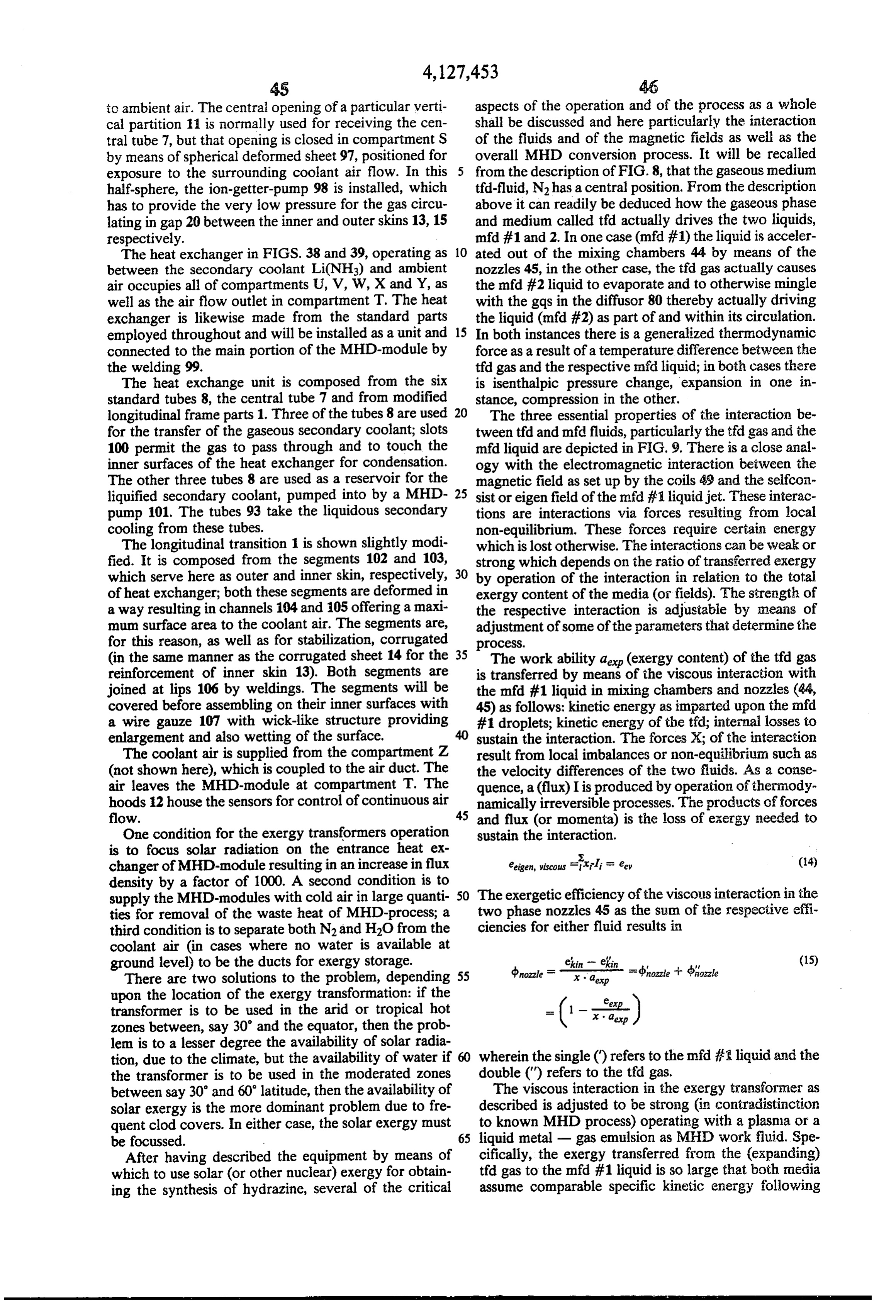
Page 38
interaction in the nozzles 45. The decisive parameter in energy from the mfd-workind fluid #1 and to transfer it FIG. 9 is the relative proportion X of the t?id fluid in (via the systems boundary) in form of electrical energy. relation to the total mass flow. The MHD-converter is composed from numerous an x = rhya /hifa +mma (16) nular coils 49, which surround the mfd-working fluid #1 flowing free, concentric to the center axis of the for 0.2 < x <0.3, i.e. to the right of the maximum of the thesystem. The entrance of the coil system is located near specific kinetic energy e' of the mfd #1 fluid, one region, point 53 of convergence, upstream thereof and in a obtains the strongest interaction. For X-> 0 (gas-metal in which the free flowing mfd-working fluid is emulsion) as well as for X -> 1 (plasma process) the 10 betweenathecompact not yet jet. As stated above, the distance different coils 49 decreases in flow direc interaction approaches zero.
The two fluids employed here are predominantly Li tion while their diameter increases. The coils are in and N2. They interact in a temperature range between serted into statorblocks 48 formed of comb like con 750 K and 850 K. One can in fact obtain a ratio of d'= struction so that, on the one hand, the magnetic field is e'kin/x-ae = 0.5 and d"= e"kin/x.ae = 0.3with a 15 and on the travelling guided for along but outside of the free jet, other hand forces are transferred from the total nozzle efficiency is nozzles= 0.8.
Usinge' and e' separately is the logical result of free jet to the exergy transformer coils.
a strong viscous interaction. Since the t?id gas (N2) has The coil system is a three-phase system, in general transferred in nozzles 45 the maximum possible exergy excited with the same constant frequency f, and is cou and is "exhausted' in this respect, it would not serve pled with a capacitor bank to be able to oscillate self. any purpose to run both fluids through the MHD con 20 excitedly. Electro-magnetic energy is shifted periodi verter process. This is quite different from MHD pro cally between the coils and the capacitors; the magnetic cesses with weak viscous interaction. It is for this reason field generated by the coils forms in total a magnetic that one separates the fluids in compartment J. This in wave or travelling field with a phase velocity decreas turn permits the utilization of e"ki of the tfd gas for ing in direction of motion:
obtaining the isothermic compression in compartment 25
Q, at low temperature. The specific kinetic energy ekin phase = (a/k) = (2at f). (W217) (17) of the mfd-working fluid 1 is extracted in form of elec A is proportional to the distance of coils, c) = 2alf, k = trical energy in the course of the electro-dynamic inter 27t/N(wave-number).
action in compartments K and L. FIG. 10 shows the 30 The electro-dynamic interaction caused by this de transfer of compression work. vice, is essentially an interaction between two magnetic In analogy to the viscous non-equilibrium interaction fields, which are the field Beer of the coils and the between thetfi and mfd #1 fluids, I now proceed to the field Been carried along with the mfd-working fluid 1 at description of the electromagnetic interaction in the the velocity of fluid fluid. The exergy transferred dur MHD generator. ing interaction is energy of the electro-magnetic field. The working fluids of the exergy transformer are 35 The reason for including coils as well as the mfd #1 separated in compartment by means of two steps. In liquid in the interaction is to be seen in that both of them the first step the homogenous distribution of both fluids are the conductors for electric currents which in turn - as can be found within the two-phase nozzles - will generate the magnetic fields. The mfd-working fluid, in be disturbed downstream of the nozzle. This has been addition, supplies the exergy to be transferred during achieved by the parallel operation of the several nozzles interaction at the expense of its kinetic energy. The 45 all oriented towards an axis and to point of conver interaction is based - in the same way as does the viscous gence 152, common to all nozzles. The non-gaseous and thermal interaction - on a local non-equilibrium, phase has a much higher density and, therefore, higher given by the relative velocity ('fluid-phase) between inertia than the gaseous phase; it tends to maintain the 45 both magnetic fields. At the origin of the second field, initial direction concentrating itself in the neighborhood within the mfd-working fluid #1, an electrical field E is of the axis common to the nozzle system upstream of generated (due to the transformation the point of convergence, while the gaseous phase ex nous Maxwell-equations for an inertialofsystem the homoge
pands to fill the empty space of compartments H and J tion):
around the free jet being formed. Within the area of jet formation X-> 0, outside of the free jet in being X-> 1; 50 as
in both these regions the strength of viscous interaction decrease continously. The electrical field exerts a force on the electrical Due to the components of velocity of the converging charges within the fluid, and it is this force, which is the stream normal to its (desired) flight direction, and due generalized force of interaction - not the Lorentz to some residual weak viscous interaction a compact force. The resulting (generalized) flux is the electric liquid mid-free jet will not be formed spontaneously; the gaseous phase, at the other hand, will be expanded fur current, mfd #1 given by the electrical conductivity or of the working fluid; the specific current density j is ther as caused by the decrease of cross section (com (due to the fact, that the velocity vectors are parallel in partment J) for flow towards to the suction channels.
The second step of separation results by electromag 60 this interaction):
netic interaction. Kinetic energy of the mfd #1 working J = gE = - as 'hasek Bextern (19) fluid is extracted and re-supplied in form of electrical s is the slip defined by - s = (vtuid-vphase)/phase energy; by this, forces are exerted on the different drop The specific internal consumption for sustaining the lets performing work to stop motion normal to the bulk interaction, eigenconsumption of interaction, is given (axial) flight direction, causing them to coagulate. 65 by:
The MHD-converter proper can be defined as that ms -s.
area of the energy transformer, in which the electrody eeigen MHD - (j.E) = 92 v2B2 extern (20) namic interaction takes place in order to extract kinetic
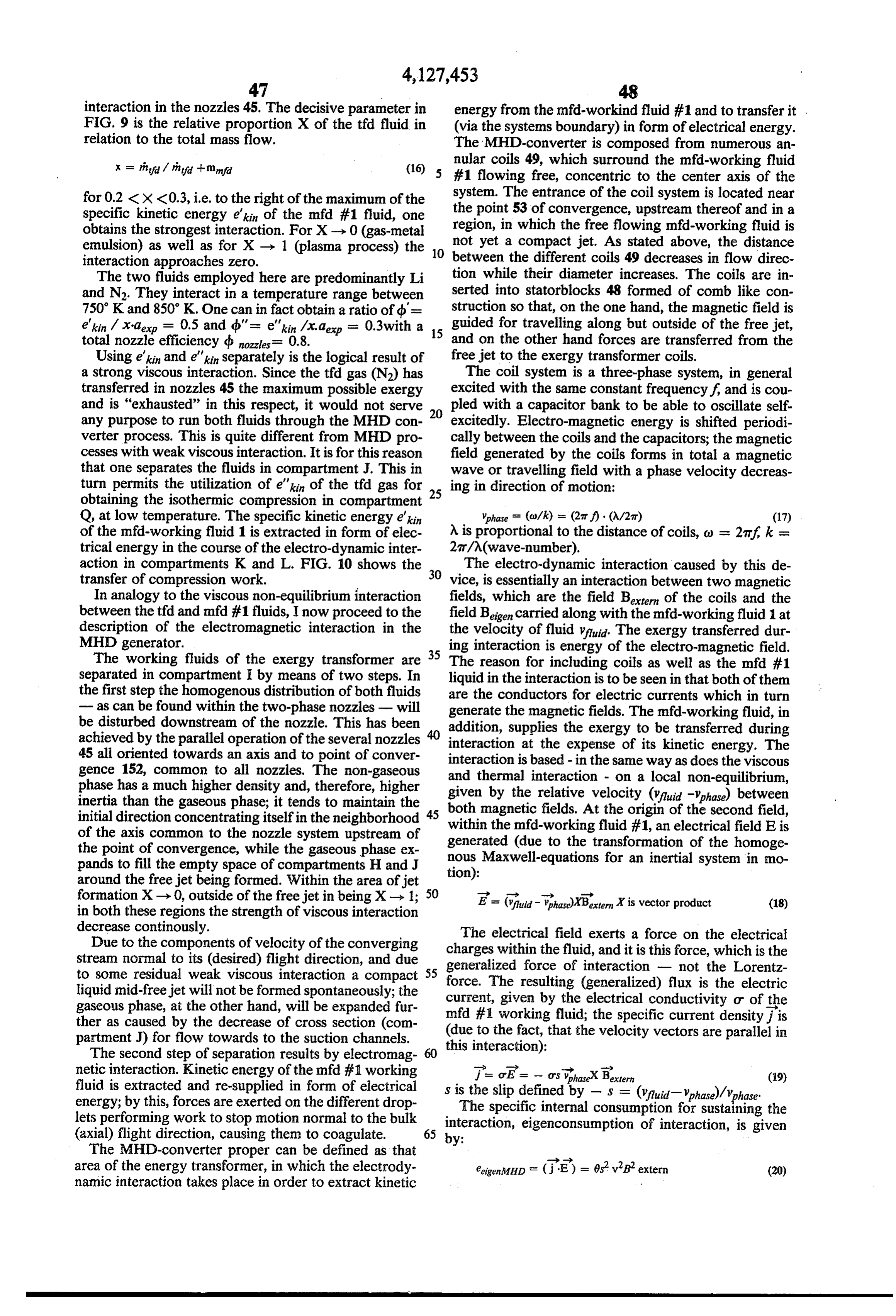
Page 39
Exergy for extraction is transferred during interac tion by the field Been. That field Beigen can be calcu (29) lated from the inhomogenous Maxwell-equation with j to be the source-term. Beigen is shifted in phase in regard 5 to Bextern by a phase angle of T/2. This is the reason, one can calculate the amplitude Been from the other amplitude Ben without considering the total field This electro-magnetic interaction as described thus Botaf. far does not include the stabilization of the free jet - Batal : Brian +j |Beni focussing of mfd #1 working fluid to obtain a compact (21) 10 jet, guidance and focussing when flowing within the
P = -1) The ratio of both amplitudes is: coil system - nor does it include the electro-synthesis of hydrazine. All these different processes consume exergy for the work to be expended on and in the jet;
Peigen e S . ( 1 5 this work must be performed also by making use of the k, base ) above discussed interaction, because the jet flows freely Bextern and is not in contact with any wall. For this purpose,
with Rn = Otuuoy phase/k being defined as magnetic additional generalized forces according to equation (18) have to be generated by local variation of the slip-s and
Reynolds-number. u = t4 loVs/Am, u = relative permeability of the liquid. 20 of the external Bextern. The exergetic efficiency disconverter The stability of interaction leads to the condition: of the non-idealized interaction is always lower than dbMHD, for this number is related to an infinitively ex his-RS 1 (23) tended undisturbed field and a constant slip. It should be noted, that the slip -s of the MHD-con it s-R = 1 is the condition for maxipal strength of tion ofisjetnotforconstant 25 verter (locally) even without stabiliza the following reason. If all the coils 49 interaction; in this case is Beigen = Bextern, and the were to be excited with the same frequency f. then the energy of the field is proportional to:
phase angle between voltage and current should be the
F 2 Baxtern same for all coils. This, however, means that Been (24) 30 =|Bugen and, hence, -s-Rn = 1. Because Rn is propor tional to "phase/o and must decrease along the fluid
The power factor of interaction is given for his-Rn. path, the condition of a constant phase angle, db = const 1: can be met only by increasing the slip in flow direction. The focussing of flow at the entrance of MHD-con
25 35 verter is achieved by changing the sign of the slips as
Fistern -- Pigen well as by proper adjustment of field Baxtern at the en trance section J (which can be supported by a surface separator upstream). The jet as formed thereat runs
The maximum value is (in this first order approxima over a distance of a few wavelengths under-synchro tion) cosd 1/V2 = 0.705. 40 nously, not over-synchronously, exergy is supplied to The exergy for this interaction is used both for inter the jet at that point; the distortion of the magnetic field nal, i.e. eigenconsumption and, to a much larger extent lines at the entrance to the converter results in focussing to maintain the local non-equilibrium which means the forces klorent acting on the fluid particles in which a continued generation of the field Been from the cur current can flow. For this purpose the first coil or the rent-density j within the mfd #1 working fluid. This 45 first few coils, adjacent the entrance (compartment I) second part can be calculated from the specific force are not excited together with the other coils; the phase exerted by the external field via the currents jupon the velocity of the magnetic wave and its harmonics can, liquid: therefore, be controlled independently. A similar method can be used for augmenting the
Rarent = xBien (26) 50 synthesis of hydrazine; it is possible, as an example, the last part of the coil system of MHD-converter to oper
To shift the mfd #1 working fluid at the velocity ate in the brake-mode by reversing the phase velocity. 5uld under the (retarding) influence of this force, the This method also might be based on a separate excita specific work tion of that part of coil system. -) 55 After having described viscous and electromagnetic aMHD = (Vuldklorent), scalar = -o's fluid ' 'phase' extern (27) interactions, I now turn to an overview as well as details of the principles of the MHD-process within the exergy has to be performed, and will be taken from the kinetic transformer and regarding MHD-converter, two-phase energy of the fluid. Inertia force of fluid and Lorentz nozzles 45, recuperative heat exchanger (compartment force have, therefore, to compensate each other. O) and the diffuser 80 for recompressing the tfd gas. The net exergy transferred during interaction is: It is the advantage of the free jet MHD-converter operating with a radial field, that the jet will be stabi lized in the direction of axis of coil system. The currents - MHD = a MHD (1 - eigen
EfMHP) (28) induced are annular currents and flow anti-parallel to those in the coil for excitation. The problems resulting from the use of side bars and of finite width as known
The exergetic efficiency of interaction is given by from flat channel type MHD-converter have been (the well known formula): avoided. A real problem is posed by the condition that
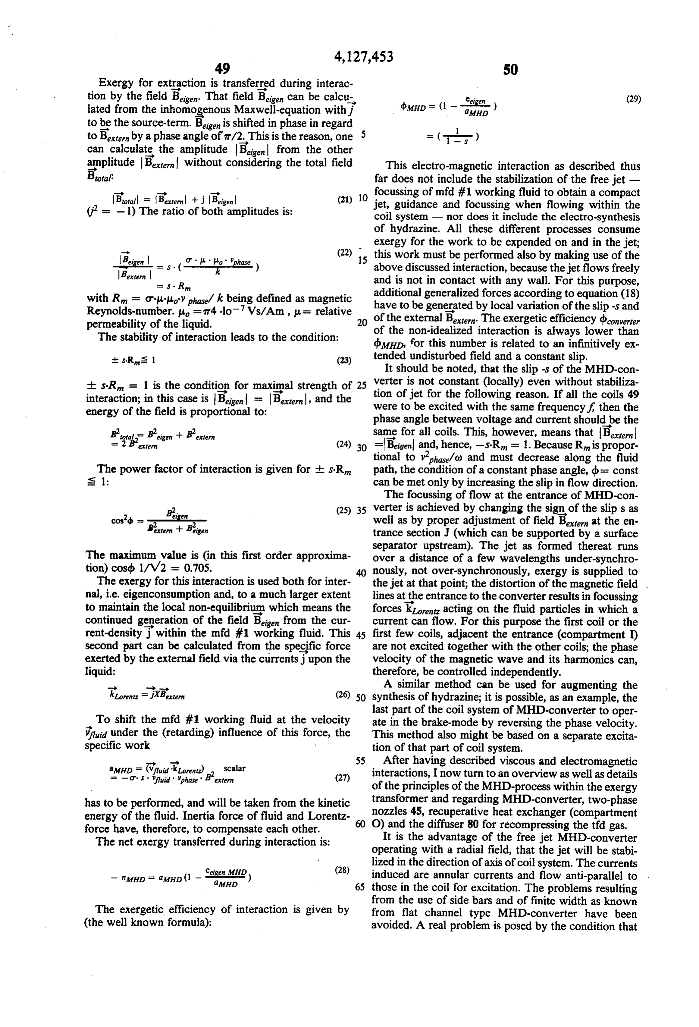
Page 40
the external magnetic field must be closed by means of and through the jet; the flux density being necessarily (0/27) = 2,5 kHz very high. This is a reason for limiting the wavelength; y' = 350 m/s .. .. this length should not exceed in average 0.1 m. The high p'nd F 1.0 g/cm for Li-LiNH2-Fe . velocity of the fluid has as a consequence that the 5 Fin/F = 0.2the only free parameterisu, which is the MHD-converter will be operated at a frequency in the permeability of the liquid to which iron particles kHz-range. Due to the skin effect in Cu, the currents have been added. Under the stated conditions, the will penetrate no more than 0.5mm; the coils 49 are parameter is u = 4.9. Since iron has a permeability actually made from small tubes with a thin wall, cooled 10 roughly between 100 and 1000, rather small quanti inside by a coolant. ties of iron particles suffice to obtain that low per For Maverage = 0.1m, phase average = 250m/s follows f meability for the liquid as a whole. Under these = 2.5 kHz. The electrical conductivity of Li is at 750K assumptions the power density of electro-magnetic about or = 107 1/Om; for the Li-LiNH2 solution of 10 interaction within the free jet converter amounts to 1/(2m is a good estimate. The magnetic Reynolds-num 2.56 kW/cm, the average magnetic Reynolds ber is: 15 number R - 25, the average slip - s = 0.04, the average slip frequency -s f = 100 Hz, the aver
R = -74. 10. 10.250. (0,1/2n) = 5 p. age loss density (in form of heat) is about 100 wherein is the permeability of the mfd #1 liquid. That
W/cm (equivalent to the power density within the liquid is made to assume a permeability by adding mod 20 blanket of a fast breeder reactor). The specific est quantities of iron to serve as the catalyst for the kinetic energy of working fluid at entrance is y/
Li-NH2-synthesis as well as the bipolar electrodes for 2 = 61.5 Ws/g. A free jet with an entrance diame the Li-NH2-electrolysis. The use of iron can also solve ter of d = 3 cm has a fluid power of about 15 MW the problem of a strong electro-magnetic interaction if increased in diameter to de = 6.7 cm. Due to -s even within the free jet MHD-converter of the exergy 25 << 1 is b MHD ~ 1.0. Under the assumption of a transformer The specific work a MHD performed during more realistic exergetic efficiency of MHD-con interaction (27) is related to unit volume while the spe verter of converter = 0.75 the net electrical power cific kinetic energy of the fluid valuid/2 is related to unit extraction is Nelectrical = 11.2 MW. massflow. Therefore, if the steady state of operation, The induced electrical field Eaerage is given by equa the specific work of interaction, integrated over the 30 tion2.5(18) and for the brake-mode with se 1, Eel V/cm, which is sufficiently high for the LiNH volume of the free jet, must be the same as the differ electrolysis with its specific exergy consumption of ence in total kinetic energy of the jet and before and about 2.2 (electron) volts. S 2 1 results from phase after the interaction: inverted connection of the coils more downstream, but The first basic condition for the exergy transformer excited with and by the same frequency and preferably is: 35 included in the oscillator coil-capacitor system as a whole.
F. L y: y (30) The residual kinetic energy of both the t?d- as well as Ffex d? and df. di = inna (- 2 - - - 2 - ) the mfd #1 working fluid will be needed for the recircu
lation of these fluids using diffusors realizing the ram-jet principle. However, about 90% of the recompression is df = surface element normal to axis of free jet used to bring the tfd gas back up to the operating pres dl = length element parallel to axis of free jet sure for isenthalpic expansion in the nozzles 45. The y = entrance velocity of free jet total kinetic energy of both fluids, at the end of viscous y' = exit velocity of free jet
F = entrance cross section of free jet 45 interaction (15) amounts to:
F = exit cross section of free jet m ekin me"kin r - in "
F m" aerp - ine - eigen viscous
L = length thmid = p.mpd. vin Fin = pnja vertex F rh' = (nozzle + d"nozzle) ria . x . exp (32) = mass flow rate of mfd-working fluid 1 p'd = density of (liquid) mfd-working fluid 1 50 Kinetic energy will be extracted from the mfdif1 working fluid within the MHD-converter according to
The condition (30) can be met under the following equation (30):
assumptions: th- e'en (1 - (F/F)) = 1 famHD df. di
2. c = const
The t?d-working fluid is, of course, not affected by the processes within the converter. The residual kinetic 3. Bettern a const energies are:
5. - S << 1 in ein (Fin/Fox 2 Aresidual mi?d (33a) then: he"kin - Eresidual yd (33lb) The principle of ram-jet operation demands, that the
extern F. Fex
Pinfa
(31) residual energy of the respective working fluid covers both the theoretical compression work, the internal, for:
eigenconsumption as well as work for recirculation within the loop. The second basic condition for the
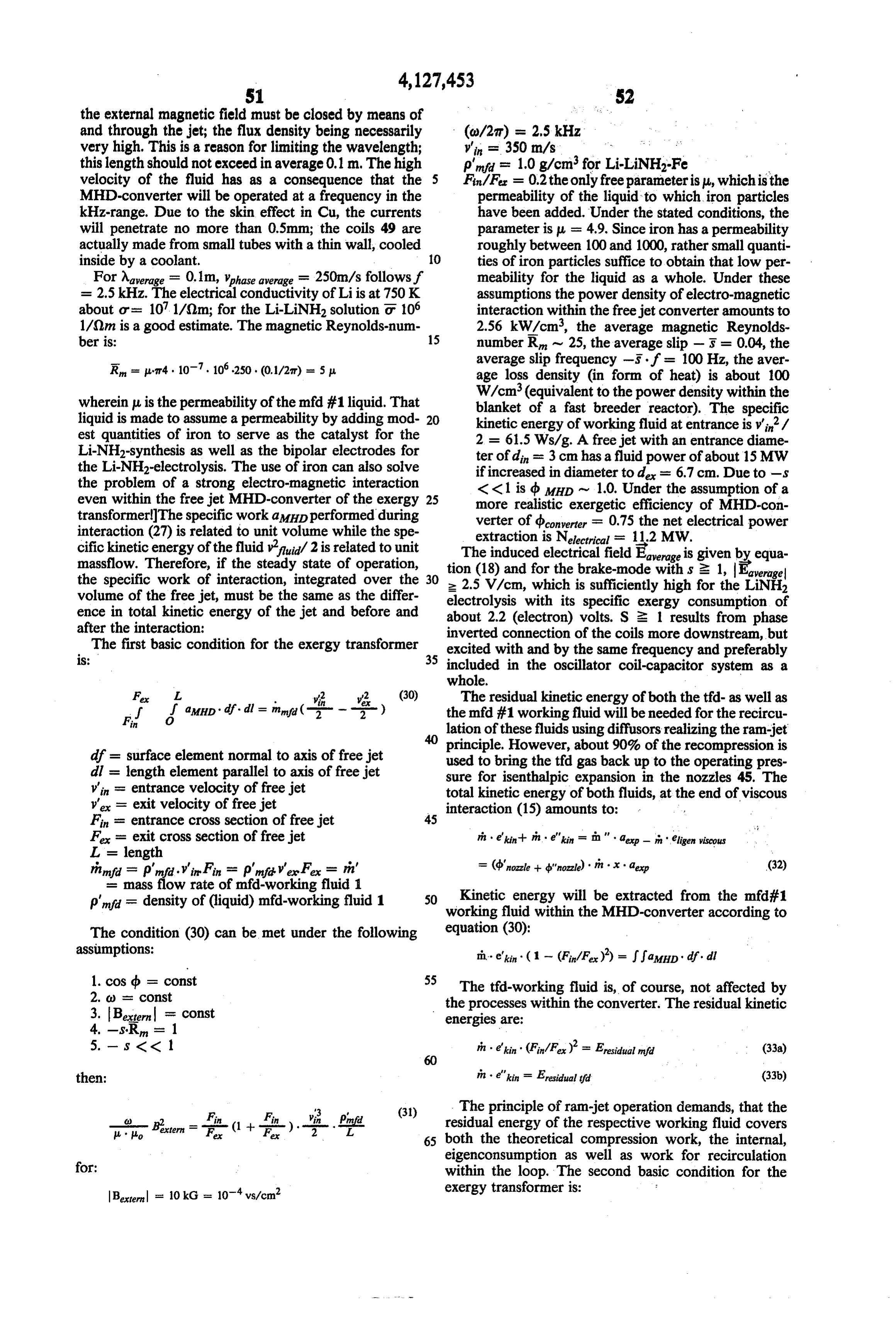
Page 41
In order to reduce the friction losses during recupera - - fin 2 . f y f (34a) tion according to the limits given by the second condi in ein ( Fex ) = n : (alomp eigen comp eigen recirc) tion (34b) or (36) respectively, the velocity of the tfd working fluid has to be decreased by adiabatic decelera
FF (34b) 5 tion within diffusor (compartment N). The eigencon
sumption of exergy for th recuperation can be approxi
The condition (34a) for the mfd # working fluid mated applying the Reynolds-analogy between the spe (which is the basis for the project MHD-staustrahl cific heat flux and the shear-tension:
rohn') with an one-component mfcd-working fluid) has O been met without any major difficulties. The compres (37) sion work is calculated to be acon = (pupper - pio) / m" eigen recirc s= ( N2 '' 2 ( upper low. ) p'na due to the incompressible fluid. The theoretical me v2. . A T' stagnation pressure is for the assumptions made before about 28 bar, which is sufficiently high to tolerate high 15 y' is the velocity during recuperation, AT" is the tem exergy losses by the jet capture in compartment M; the perature difference between hot and coid fluids, is a residual energy is 0.04 times the kinetic energy of the factor describing shape of heater tubes. (37) is the sec working fluid before entering the MHD-converter.
') ramjet tube ond term of the right side of equation (35) for d",ane; The condition (34b) for the tfd-working fluid, how 20 K must this term should not exceed 0.1. For = 0.81, AT = 50 be, therefore, y' s 35 m/s.
ever, is the critical one and is decisive for the realization FIG. 11 is an temperature-entropy diagram for both of the exergy transformer. In the case of isothermal the t?d-working fluid N2 and the mid #1 working fluid compression in diffusor 80 according to (2) and (3) one Li-LiNH2-Fe. The tfd-working fluid is decelerated and obtains compression work to be equal to: adiabatically after separation from the mfd 4/ working a"comp - Tupper/Tow' exp 25 fluid, before recuperation (compartment N); when leav ing the recuperative heat exchanger (compartment P) it
The residual kinetic energy at the termination of will be accelerated again. The rise in temperature viscous interaction is characterized by d'ozzle follow caused by deceleration is used for heat exchange in ing (15); one can describe the exergy necessary for 30 compartment Q.
eigenconsumption during compression in diffusor 80 The pressure ratio if can be calculated from the ratio and recirculation - including friction losses within the of the expansion work utilized a = 360 Ws/g to the recuperative heat exchanger-by introducing the exer maximum possible expansion work R. Tier . 1nna = getic efficiency: 750 Ws/g:
35 1n f = (360/750). 1n ar. (38)
- ) It is t = 5.35. The specific compression work is a"comp using (35), the condition (34b) reads: = 120 Ws/g. The tfd-working fluid entering the diffu. sor 80 (after loosing thermal energy in the recuperator) ("nozzle" "ram jet Tipper/To = i (36) 40 has to be cooled, which is achieved by evaporation of the NH3 component of the mfd #2 working fluid and at
In case of this exergy transformer the condition (36) high velocity in the frontal portion of diffusor 30, In this has to be fulfilled by controlling the strength of viscous case the viscous interaction is, however, weak, due to interaction varying the ratio x /(1-x) = rhy/hind of 45 both the low densities and low fraction of NH3. Et will both fluids as well as by choosing proper the ratio of be recalled, that the mfd #2 working fluid is basically a densities p"/ p' (at beginning of expansion). coolant. The process in the diffusor 80 is comparable to If 0.4 < d" < 0.45 (see FIG. 9) the parameter x that within a heat pipe. The range of parameters of this can vary between 0.2 and 0.3. The permissible range, in which d'anet may change is for Tupper = 750 K and 50 process has to be selected in such a manner, that the local vapor pressure of NH3 and the pressure of N.
T = 250 K: equalize only after the tfd fluid velocity has been de 0.74 < d"net ( 0.83 creased substantially. Thereafter, cooling by evapora tion will be replaced by cooling on wetted surfaces.
For a temperature of 300K, the figures vary only by The variation of thermodynamic states of the mfc if about 20%. 55 fluid results from its function to be a heat storage me These numbers can be reached by an adequate design. dium; it follows: Due to the following relations: A. a vi'. ri' cAT = in". x ae
c' = 4Ws/gK (specific heat at constant pressure of
Li-LiNH2); AT" (temperature range of heat storage).
Under the assumtions made before AT = 38.5 K fol.
the specific expansion work can be calculated; using x lows.
= 0.3; b'nozzle = 0.4; b'nozzle = 0.43 the expansion work The total efficiency of the process in the exergy trans is a = 360 Ws/g; from this the exit velocity of the 65 former tfd-working fluid follows to be y' = 557 m/s accord radiationshould be related to the conversion of the solar absorbed to the electricai energy at exit of the ing to the specific kinetic energy y'e/2 = 155 Ws/g. coil system; it is defined, using (8) and with Nibeing the After separation the tfd-working fluid appproaches the net electrical energy of the MHD-converter: velocity of sound y' = c = Vk R. Ter
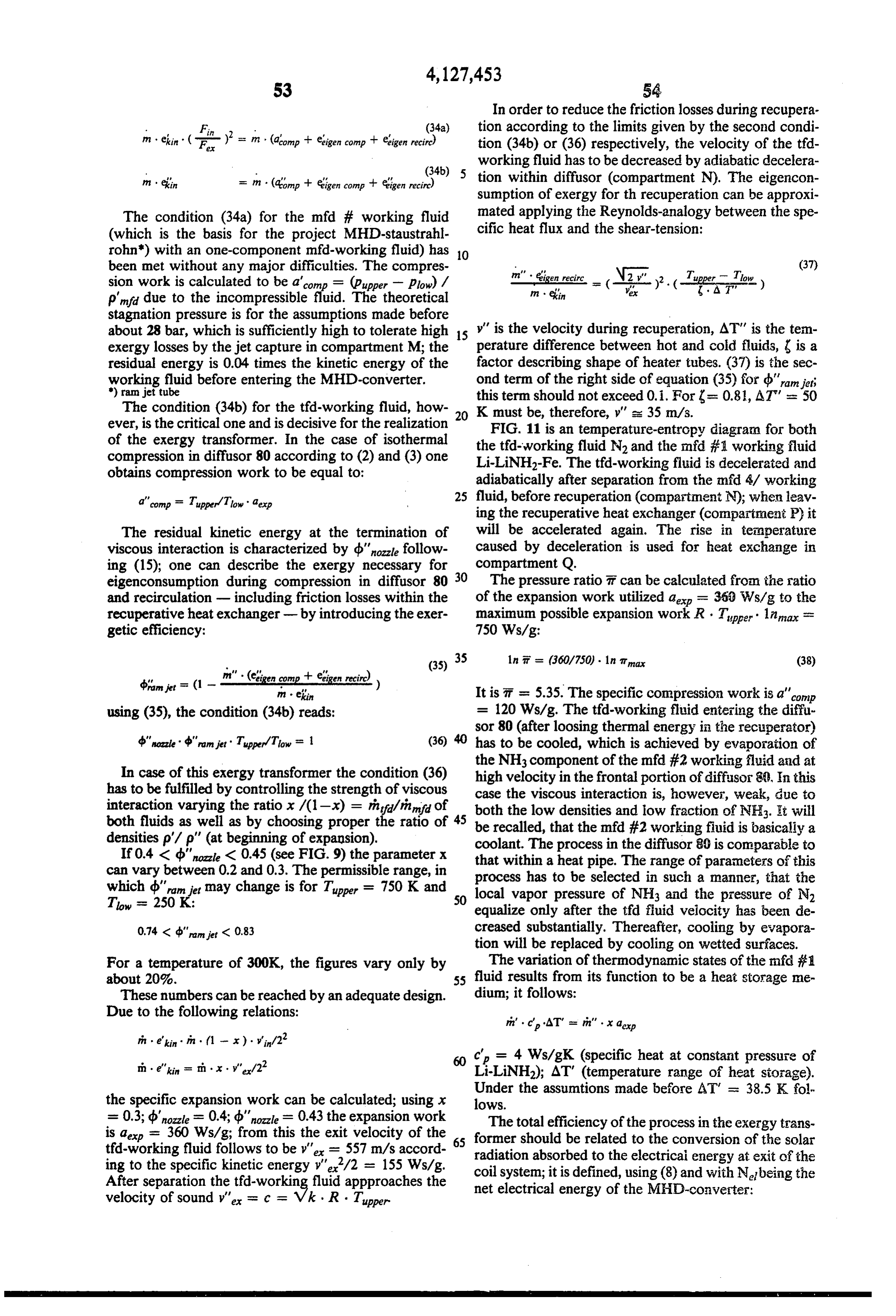
Page 42
reach technical efficiencies up to 90%; the last step of
Net . (39) (NH2)2-synthesis (electrolysis of Li-NH2), however, 7th se - = (-t-) (-- a--) needs only about 25% of the total electrical energy;
even if the efficiency of this process (not known so far) - process 'ic is much lower, its influence on the total efficiency is softened due to the low weight. A compensation of
If the efficiency (bHD of interaction will be supple losses seems to be possible utilizing by parts energy of mented by considering total eigenconsumption, and if the field Been carried along with the free jet for the the slip s is understood to be the local slip, then the Li-amide-electrolysis;
effective efficiency bonverter can be defined by using the 10 On the basis of the normally foregoing this energy is lost.
detailed explanation it first basic condition (30) as follows: will readily be understood that the peroxide synthesis JaMHD (bmHD df d = - Nel = (bconvener can be carried out quite analogously and is run on a JaMHD df d (40) simplified basis because the coil-core-liquid system does not have to operate on the basis of thermo-fluid dy
The total efficiency mh can be decuded directly from 15 namic acceleration of the working fluid (though it (32), provided the second basic condition (34a +b) is could) but a pump (187-FIG. 8) is used instead. Also, actually met: the electrical energy is applied externally, namely from the MHD converter of the hydrazine and solar exergy 7th - d'hozzle' deconverter. (1 - (Fin/Fe') (41) exploiting system. The a.c. electrolysis is, therefore,
From the data mentioned before one finds m = of used by interaction between coils and a watery solution 0.288; from this, the exergetic efficiency of the process metallic KOH used as circulating working fluid here, with particles, preferably iron, but possibly Cuor Al is determined to be drocess = 0.432 due to me = 0.666. being interspersed
It is well known that processes in MHD-systems lish conductivity inforthe the same reason, namely to estab otherwise poorly conductive running both on lines of constant enthalpy and on iso 25 bares, will have a total efficiency, which is - in theory electrolyte. The voltage needed here for electrolysis is also the result pf the effect as expressed Maxwell (vec - comparable to those in nuclear power stations. tor) equation B -- curl E = 0, and integration of E MHD-systems of this kind, however, have been based on a weak viscous interaction maintained within the along a closed electric field line, looping around the axis MHD-converter proper parallel to the electro-magnetic 30 of fluid flow, yields the voltage U (not a potential differ ence in a potential field, there is none) which is directly interaction which is, therefore, also a weak one (extrac effective tion from d.c. power at R < 1). These systems can on electrons to move them from OH to K. hardly be operated without movable boundaries (tur In the following, it shall be described how the hydra bines as well as compressors). zine and the generation of H2 (needed for the hydrazine To summarize and conclude: The substantial im 35 synthesis) with concurring production of (OH)2 can be provement of the present MHD-process within the carried out by one basic fluid circulating system. For exergy transformer expressed by the high total effi this I turn to FIG. 42. In toto, this system is more eco ciency if compared to the well known MHD-processes nomical (fewer parts, no H2 storage, no electric trans with condensation of the tfd-working fluid and recircu mission). The system is based on the (justified) assump lation by the ramjet principle, is achieved by utilizing tion that as intermediate products M-NH2 and M-OH the residual kinetic energy of both fluids. In addition, can be used with M standing for the same metal, partic recuperation takes place independent from the expan ularly the same alkalimetal. The system, furthermore is sion in the nozzles. It is important to note, that the based on the "compromise' that only one of these inter electro-magnetic interaction includes separation of the mediate products is synthesized electrolytically, the two working fluids, and that this interaction takes place 45 other one chemically.
at high velocities and with high frequencies based on a The box 308 in FIG. 42 depicts the flow chart of this free flying jet. The increase of the magnetic Reynolds combination synthesis. Reflector 289 is the same as number Rm up to 25 by ferromagnetic components of before and the same is true for the accumulation and the mfd-working fluid #helps to solve the (old) problem extraction facilities 302, 286, and 279. A circulation 290 of adapting the thermodynamic acceleration of the t?d 50 in unit 308 is now a circulation of M and M-OH, M working fluid to the energy extraction in the MHD being for example Li or K. Block 291 denotes the heat converter, which was solved in all known liquid-metal ing of that fluid by solar energy and block 292 denotes MHD-systems only by tolerating very large losses of the adding of hydrogen and nitrogen to that liquid so exergy. It should be noted at last, that the exergy trans that functionally M-NH2 is generated in block 293. former will be operated in a technical most feasible 55 This will be a catalytic reaction with iron for example relatively low range of temperatures which so far as not serving as catalyst. Please note, that this amid- forma attainable to the systems mentioned before with both a tion is not linked to the use of lithium but works with strong viscous and electromagnetic interaction. other alkalimetals as well.
mih according to (41) is not the total efficiency of the Thus far the situation is very similar to the function exergy transformer, or, in other words, is not the effi and steps as was explained above with reference to FIG. ciency of the storage of solar exergy in form of free 8. However, the liquid now continuing to circulate is M, enthalpy of the chemical compounds (OH)2 and (NH2)2. MOH and M-NH2. At point 295 and 28, water is Rather, mih is a very good approximation due to the fact, added to the circulation. This is actually the entrance to that the (exergetic) efficiency of chemical reactions is the accelerator nozzles such as 45, supra. Thus, water is quite high in general; the internal, eigenconsumption of 65 used here as the t?id fluid. The water evaporates and exergy is low. It seems to be not of major importance, expands along 296 and accelerates the working liquid as that this eigenconsumption of the chemical reactions is before. However additionally, the water reacts with the not included in m. The (OH)2-synthesis was found to M-NH2 and forms MiOH -- (NH2) + H2. In other
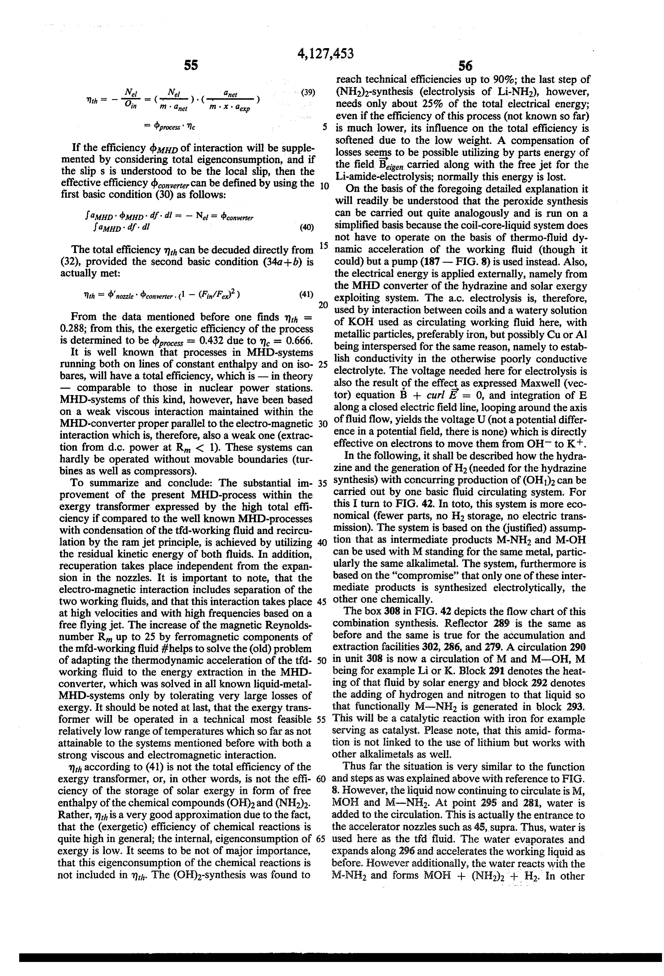
Page 43
words, the hydrazine is the product of a chemical reac adding an inert gas to said solution to form a two tion of metalamid and water under formation of H2 and phase flow in which occurs intimate heat exchange hydrazine. Additionally, the residual metal is also con between the gas and the heated solution, thereby verted into MOH + H2. heating the gas;
Following the acceleration, the liquid phase consists expanding the gas in the two-phase flow thereby essentially of MOH and M while hydrazine and hydro causing the liquid to be accelerated by the ex gen accompany the tfd gas (namely H2O) in the liquid panded gas;
gas separation process, Please note, that more water is magnetically energizing the liquid phase of said flow added at 295 than can react with the M-NH2 and the to obtain electrolytic separation of the alkali metal metal so that all of the M-NH2 decomposes under for O from the amid under formation of diamid; mation of hydrazine while excess water (steam) serves separating the diamid from the metal and returning as the t?id gas performing the acceleration producing the alkali metal for anewed mixing with hydrogen work on the liquid phase. and nitrogen as per said mixing step; and The steam and H2 are separated at 297 analogous to compressing, cooling and returning the compressed the gas - liquid separation as described above. The gas 15 inert gas for continuing its use in said adding step. includes also hydrazine which is precipitated by cooling 2. Method as in claim 1, wherein the formation as in 301 because hydrazine has a higher boiling point than carried out by catalytic reaction, a catalyst circulating water. The water - H2 mixture (gaseous) is extracted as and being mixed with said metal. tfd fluid and subjected to recuperative heat exchange in 3. Method as in claim 1, wherein the catalyst is a 304 with isothermic compression (and condensation of 20 higher the water) in 305 which is simplified in FIG. 42 but may bipolar melting metal which remains solid and serves as electrodes in the accelerated liquid phase on well be constructed analogous to the detailed arrange which the alkaline amid separates into amid and alkaline ment of FIG.8. However, a mere recompression under metal.
cooling by air may suffice.
The cooled and recompressed H2 and water is recir 25 4. Method as in claim 1, wherein said heating is pro culated and heated in the recuperative heat exchanger. vided by focussing of solar radiation. 5. Method as in claim 1, including focussing the liquid
In view of the high pressure, the water remains in liqui phase dous form so that the H2 can readily be separated there of theofgaseous said two-phase flow under reduction of density phase during said expanding to obtain from in 282 for separate injection into the liquid fluid circulation respectively at 292 and 295. 30 separation of the gaseous phase from the liquid phase. As far as the metal-hydroxide is concerned, it is sub 6. Method as in claim 1, wherein the inert gas is nitro jected to mechanical and/or electromagnetic focussing gen. 7. Method as in claim 1, wherein the diamid is sepa at 298 (please note that iron particles are dispersed in rated from the metal by phase separation and con this liquid), and in 284 the MHD conversion process takes place whereby substantially all electrical energy is 35 densed.
8. Method as in claim 1, whereinfinely divided iron is consumed to obtain electrolysis M-OH)2. The (OH)2 used as catalyst as well as bipolar electrodes to obtain is flushed out at 285 and the t?id cushioning gas is also said electrolytic reaction.
separated from the liquid phase at that point. Please 9. Method of producing hydrazine comprising the note tht the (OH)2 is produced as a vapor that separates steps of:
readily from the MOH-Mjet and will be condensated providing a first circulation of a magneto-hydro dy for extraction.
The block 303 denotes jet capture and to kinetic ener namic work fluid;
gy-to-pressure conversion for obtaining a return flow of heating the work fluid in the liquidous phase by the mixture of metal and metal - OH to the solar heat means of externally developed and applied thermal exchange and collector 291. 45 energy;
The righthand portion of the drawing shows basi providing a second circulation of an inert gas, the two cally a flow path for air, 275, sucked into the system for circulations being partially linked to obtain a two cooling (heat exchange 305), separation of water 278 phase flow;
and extraction of nitrogen, 277. Reference numeral 276 introducing nitrogen and hydrogen into the circula refers to a blower which sucks the air. That blower may 50 tion of the work fluid as heated to obtain a mixture have to be run by electrical energy from converter 284. of that fluid and of an amid as a compound with a That, however, is a very small load and will not inter portion of the work fluid, ahead of linking said fere with the operation of the MHD generator. circulations, the work fluid heating the gas by heat It can thus be seen that the MHD conversion process exchange following the linking of the circulations; is used only for (OH)2 generation. As far as the hydra 55 subjecting the linked circulation to a pressure-to zine generation is concerned, the essential functions kinetic energy conversion process under expansion performed by the MHD process is the reconstitution of of the gaseous phase and acceleration of the liqui the metal so that the solar energy can generate dous phase;
M-NH2 which subsequently reacts with water to ob continuing the flow of said mixture as a portion of tain MOH and (NH2) as well as H2 to be used in the said first circulation and in a magneto-hydrody synthesis of M-NH2. namic process to obtain electrolytic separation of I claim: amid from the compound with said portion of the 1. Method of producing hydrazine comprising the work fluid, followed by formation of diamid; steps of: the work fluid continuing in said first circulation; mixing an alkali metal with hydrogen and nitrogen; 65 separating said gas from said work fluid; heating the metal with the mixed hydrogen and nitro cooling and pressurizing the gas; and gen and causing formation of metal amid as solu returning the pressurized inert gas outside of said tion in the metal; linked circulations.
Page 44
10. Method as in claim 9, wherein finely divided iron tain a two-phase flow in which the gaseous medium is added to the work fluid rendering the first circulation is heated by the liquidous medium; ferromagnetic, and serving as bipolar electrode in the (b) expanding the gaseous medium in the flow to electrolytic process. obtain acceleration of the liquidous medium; 11. Method as in claim 10, wherein the work fluid is 5 (c) separating the two circulations including forma lithium, the iron provided for catalytic formation of tion of liquid jet riding on a gas cushion; said first lithium amid as said compound, the electrolytic separa circulation providing step including additionally tion being an electrolysis of the lithium amid to obtain subjecting the liquid medium, after said separating lithium and diamid. from said gaseous medium, to MHD processing for 12. Method as in claim 9, including the step of focus O electrolitically decomposing the alkali amide in the sing the liquidous phase under separation of the gaseous jet to obtain hydrazine and phase for separating said circulations, to obtain a free (a) said second providing step including recompres flowing jet of the liquidous phase, and providing a trav sing the gaseous phase at a relatively low tempera elling magnetic field for guiding and slowing the jet ture following the separating, so that the recom under formation of eddy currents therein to obtain said 15 pressed gaseous phase obtains a high pressure prior electrolytic separation wherein said solid phase serves to being mixed as per step (a). as bipolar electrodes. 26. Method as in claim 25, wherein the MHD pro 13. Method as in claim 9, the inert gas being N2 or a cessing includes the providing of a radially symmetrical nitrogen compound, the liquidous phase being an alkali travelling magnetic field, the slippage between the ac metal. 20 celerated liquid phase of said jet and said magnetic field 24. Method as in claim 13, wherin said compression is causing annular currents to be induced in said jet. carried out under evaporation cooling, causing LiNH3 27. Method as in claim 25, including the step of focus to evaporate in the flow of compressing nitrogen. sing the liquidous medium by means of inhomogenic 5. Miethod as in claim 14, including the step of caus magnetic field.
ing the LiNH3 to condensate by evaporative cooling of 25 28. Method as in claim 27, including adding a sub an air cooled medium. stance to the liquidous medium to render it ferromag 56. Method as in claim 9 and including extracting netic.
enthalpy from said gaseous phase following separation 29. Method as in claim 28, wherein the droplets of the prior to compressing of the gaseous phase and recupera liquidous medium are urged in direction of declining tively returning the enthalpy to the compressed gaseous 30 field strength to obtain coagulation and formation of a phase prior to adding it to said metal. free but compact jet no longer containing the gaseous 7. Method as in claim 16, wherein said compressing medium to any significant extent.
results from converting residual kinetic energy of the 30. Method of obtaining electrolytic decomposition nitrogen into pressure. of a compound comprising the steps of: 18. Method as in claim 17, wherein LiNH3 is added to 35 providing an accelerated flow of a liquidous working the gaseous medium while being compressed and is fluid, there being finely divided metal particles carried along and caused to evaporate to obtain isother provided in the liquidous phase moving therewith; nic compression. focussing the accelerated liquidous working fluid into A9. Method as in claim 18 and including the step of a free flowing narrowjet;
separating the LiNH3 from the nitrogen by causing the 40 providing a transversely extending magnetic travel LiNH3 to condensate in the region of low velocity of ling wavefield to the liquidous jet to obtain a circu the nitrogen following compression. lar electric field therein resulting in electrolytic 20. Method as in claim 9, wherein the gaseous phase decompositioning of at least a portion of said liqui is added to the liquidous phase in a condensed state to dous working fluid in the jet, the metal particles evaporate and expand on being mixed with the liqui 45 serving as electrodes;
dous phase. separating at least one resultant from the electrolytic 21. The method as in claim 9 wherein said subjecting decompositioning from the remainder of the work step is carried out by converging the work fluid and gas ing fluid; and followed by divergence under decompression of the gas adding to the working fluid to renew the decomposi to obtain acceleratin of the work fluid. 50 tioning compound thereof, 22. The method as in claim 9 wherein the subjecting 3. Method as in claim 30, including the formation of step includes mechanical focussing. an intermediate product including the working fluid 23. The method as in claim 9 wherein the work fluid itself, the intermediate producing being electrolytically is atomized and focussed to obtain a free flowing jet in decomposed.
which the magneto-hydro-dynamic process works to 55 32. Method as in claim 30, wherein the magnetic field obtain such electrolytic separation. is provided as a radial symmetric field for inducing 24. The method as in claim 23 wherein the separating annular currents in the jet.
step is carried out by said focussing so that the jet rides 33. Method as in claim 30, wherein the said liquid on a separate gas cushion. phase includes alkali-amid and alkali metal and iron as 25. Method of producing hydrazine comprising the 60 catalyst, the electrolytic decomposition resulting in the steps of: providing for a first circulation of a liquidous formation of hydrazine.
medium which includes alkali amide including provid 34. Method as in claim 30, wherein the working fluid ing a location in the fist circulation to obtain absorption includes a gaseous phase separated from the liquid of thermal energy as provided thereto; and phase on focussing thereof, the portion of the liquid providing for a second circulation of a gaseous me 65 phase following electric decompositioning being heated dium which includes nitrogen including by a heating step and return to the two-phase flow, so (a) mixing the gaseous medium with the liquidous that the gaseous phase is heated by heat exchange with medium after absorption of thermal energy to ob the liquidous phase, the acceleration of the liquidous
Page 45
phase resulting from expansion of the gaseous phase and 44. Method as in claim 43, wherein the liquidous compressing the gaseous phase following separation. phase includes an alkaline metal, the gaseous phase 35. Method as in claim 30, wherein the resulting de includes an inert gas.
composition product is a gas which separates from the 45. Method as in claim 44, wherein the liquidous liquidous phase, and including the step of condensating 5 phase includes lithium, the compound being lithium said gas. amid, the gaseous phase being nitrogen. 36. Method as in claim 30, said liquidous fluid being 46. Method as in claim 39 and including extracting an alkali metal, the adding step including adding of electrical energy from the fluid as moving through the water to obtain H2 and alkali hydroxide, the alkali hy 10 magnetic field;
droxide being electrolytically decomposed, to obtain using the extracted electrical energy to run a water (OH)2 and metal. electrolysis process for production of hydrogen; 37. Method as in claim 36, wherein the alkali metal is and lithium or potassium or sodium. feeding said hydrogen to said work fluid for use in 38. Method as in claim 36, the working fluid includ 15 47. A method step.
said adding ing water, the electrolytic reaction resulting in produc first circulation offorliquidous generating hydrazine providing a alkali metal and including tion of H2 and (OH)2, the (OH)2 being removed from (a) heating the metal by focussed solar energy thereon, the working fluid by means of heating.
39. Method of producing hydrazine, comprising the (b) adding hydrogen and nitrogen to obtain metal amid, (c) reconstituting the metal for return flow in the first steps of: circulation including magneto hydrodynamic process converting thermal energy received into kinetic en 20 ing for electrolytically restoring the metal, the reconsti ergy of a magneto hydrodynamic work fluid; tuting further including the extraction of hydrazine; adding hydrogen and nitrogen to the work fluid providing a second circulation of a gas including (a) under formation of a hydrogen, nitrogen com pressurizing the gas, (b) adding the pressurized gas pound to be included in the work fluid of which 25 to the heated first circulation to obtain isothermic amid is an educt; expansion under acceleration of the liquid phase for subjecting the work fluid including said component said hydro dynamic processing, and (c) separating and as accelerated to a magentic field transverse to the decompressed gas for return to obtain said the resulting motion to obtain electrolytic separa pressurizing.
tion of said amid under formation of diamid; and 30 48. A method as in claim 47, including the step of extracting the diamid from the work fluid while re adding water to the metal-metal amid mixture serving as turning the work fluid to obtain a circulation said gas on vaporization and also reacting in parts to thereof and including said converting and said obtain hydrazine, metal hydroxide and hydrogen - the adding. magneto-processing providing electrolytic separation 40. Method as in claim 39, including condensating the 35 of the hydroxide from metal, the hydrogen as obtained diamid following said extraction as a gas. being added as per substep (b) of the first circulation. 41. Method as in claim 39 and including adding a 49. A method as in claim 47, wherein the metal amid catalyst to said fluid for obtaining the formation of a is electrolytically separated by the magneto processing, particular compound. the gas being an inert gas.
42. Method as in claim 39, wherein the working fluid 50. A method as in claim 47, including adding finely includes a liquid phase and including the step of focus dispersed ferromagnetic particles to the first circulation sing the liquidous phase into a free flowing jet in which wherein said magneto-processing includes the forma to obtain said electrolytic separation. tion of a jet from the metal compound to be electrolyti 43. Method as in claim 42, wherein the working fluid cally decomposed, and causing the jet to interact with includes a gaseous phase which accelerates the liquid 45 coil-capacitor system to obtain a travelling magnetic phase under expansion, the gaseous phase being sepa field which interacts with the jet to obtain current flow rated from the liquid phase following expansion for therein sustaining the electrolysis. k is repressurization.
Provenance
- Collection
- Cited prior art
- Original PDF
- patentimages.storage.googleapis.com →
- Filed
- 1975-01-29
- Pages
- 45
- Method
- pdftotext (the PDF's own text layer) + pdftoppm 300dpi page scans
- Source
- Google Patents bibliographic record
- Granted
- 1978-11-28
- Inventors
- Reinhart Radebold
- Transcribed from
- patentimages.storage.googleapis.com →