patent · US6201313
Convection energy generator
13 March 2001
Page 1 — bibliographic record
(12) United States Patent (10) Patent No.: US 6,201,313 B1 Nakamats (45) Date of Patent: Mar. 13, 2001
(54) CONVECTION ENERGY GENERATOR 4,114,046 9/1978 Yousef ................................... 290/55 4,319,141 3/1982 Schmugge .............................. 290/52 (76) Inventor: Yoshiro Nakamats, 1105-10-1, 4,379,972 * 4/1983 Sosa et al. ... ... 290/44 Minami-Aoyama 5-chome, Minato-ku, 5,300,817 * 4/1994 Bair .......... ... 290/55 Tokyo (JP) 5,394,016 * 2/1995 Hickey . ... 290/55 5,605.391 * 2/1997 Wood ....... ... 362/35 * Y Not
ubject to anyy disclaimer, disclai h term off this the thi 6,016,015 1/2000 Willard, Jr. ............................ 290/55 patent is extended or adjusted under 35
U.S.C. 154(b) by 0 days. * cited by examiner
(22) Filed: Oct. 5, 1998 Primary Examiner Nicholas Ponomarenko (74) Attorney, Agent, or Firm Jordan and Hamburg LLP (30) Foreign Application Priority Data
Oct. 4, 1997 (JP) ................................................... 9-307781 (51) Int. Cl." ........................................................ F03D 9/00 An energy generation System utilizes convection flow of a (52) U.S. Cl. .................. ... 290/54; 290/43 fluid media caused by differences in temperature to generate useful energy therefrom. A conduit for directing convection (58) Field of Search ... ... 290/43, 44, 55, circulation permits conversion of forces associated with the 290/54; 60/643, 641.15, 641.1 movement of the fluid media in the conduit into a usable (56) References Cited energy by its effect of a generation device as the fluid media flows past Such device.
3,832,853 9/1974 Butler, Jr. .............................. 60/641 2 Claims, 9 Drawing Sheets
Page 2
Drawing sheet — no readable text.
Page 3
Drawing sheet — no readable text.
Page 4
COUNTER
ROTATION
SCREW
12 AC GENERATOR
ROOM BALCONYSIDE
MLKY WHITE
TRANSLUCENT
GLASS OR PLASTIC
FOR:
TNSEI
(IRNS
TIÑA
TRANSLUCENT GLASS OR PLASTIC
OR PUNCHED METAL
BLACK SURFACE TO ABSORB
SUN HEAT
1. SHIELD INSIDE
ROOM
D’IN HOLE TO INTAKE AIR
2. GUIDE FOR
VIS N
CONVECTION
LIN
FLOW
AIR INTAKE
Page 5
Drawing sheet — no readable text.
Page 6
Drawing sheet — no readable text.
Page 7
Drawing sheet — no readable text.
Page 8
Drawing sheet — no readable text.
Page 9
Drawing sheet — no readable text.
Page 10
Drawing sheet — no readable text.
Page 11
CONVECTION ENERGY GENERATOR The above, and other objects, features and advantages of the present invention will become apparent from the fol
BACKGROUND OF THE INVENTION lowing description read in conjunction with the accompa The present invention relates to an energy generating nying drawings, in which like reference numerals designate the same elements.
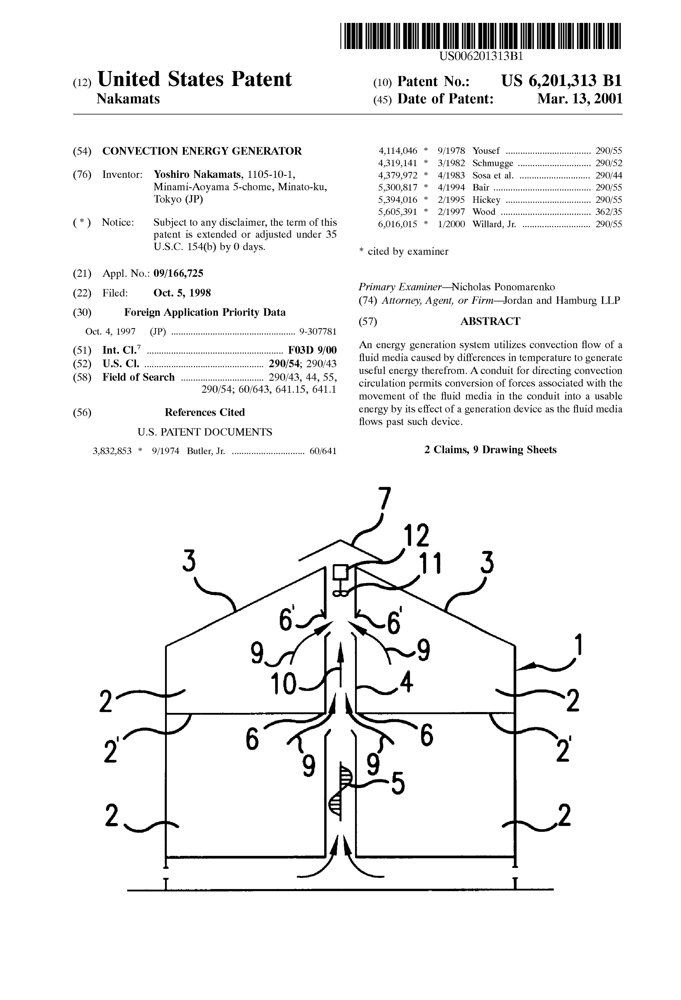
System, and more particularly, a System Suitable for use in, or external of, a house, building, factory or other structure BRIEF DESCRIPTION OF THE DRAWINGS for generating electrical, mechanical and other energy by convection utilization. FIG. 1 is a Schematic longitudinal cross-section of a first Power generation by Solar energy using conventional embodiment of a convection energy generating System in technology is inefficient, providing an efficiency, for accordance with the invention;
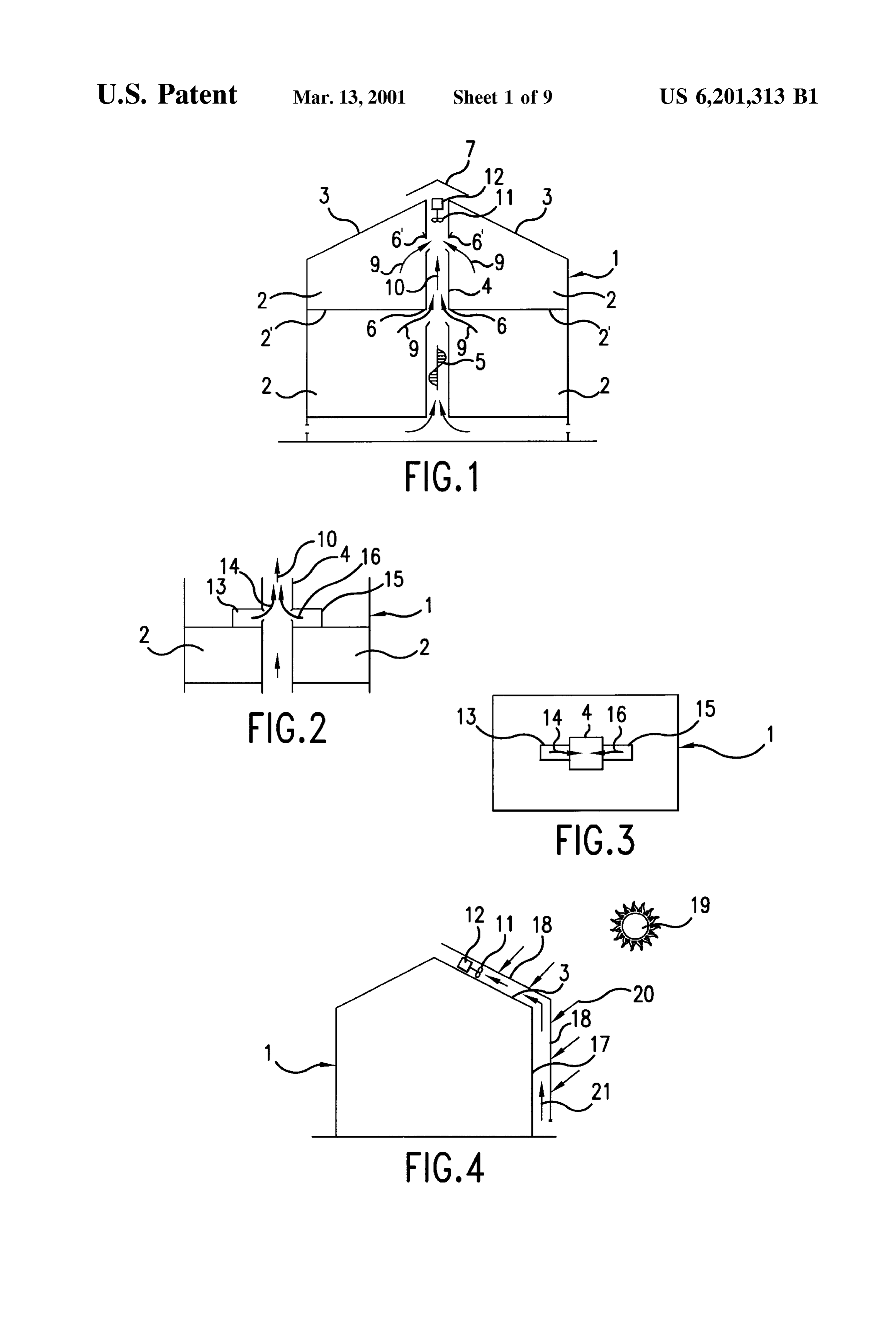
example, of about only 15%. In addition, the cost associated FIG. 2 is a Schematic longitudinal croSS-Section of a with Solar energy generation is generally high. Second embodiment of a convection energy generating Sys In living areas, and in and about various other enclosed tem in accordance with the invention;
Structures, convection is a naturally occurring phenomenon 15 FIG. 3 is a schematic plan view of the embodiment of caused by temperature differences at upper and lower indoor FIG. 2;
positions. Its usefulness however in converting the energy of FIG. 4 is a Schematic longitudinal croSS-Section of a third the air Stream asSociated with Such convention has hereto embodiment of a convection energy generating System in fore been neglected, despite the ability to efficiently harneSS accordance with the invention;
its energy. FIG. 5 is a Schematic longitudinal croSS-Section of a Accordingly, it is an object of the invention to provide a fourth embodiment of a convection energy generating Sys convection energy generating System which overcomes the tem in accordance with the invention;
drawbacks of the prior art. FIG. 6 is a schematic longitudinal cross-section of a fifth It is a further object of the invention to provide a con embodiment of a convection energy generating System in vection energy generating System which efficiently and 25 accordance with the invention;
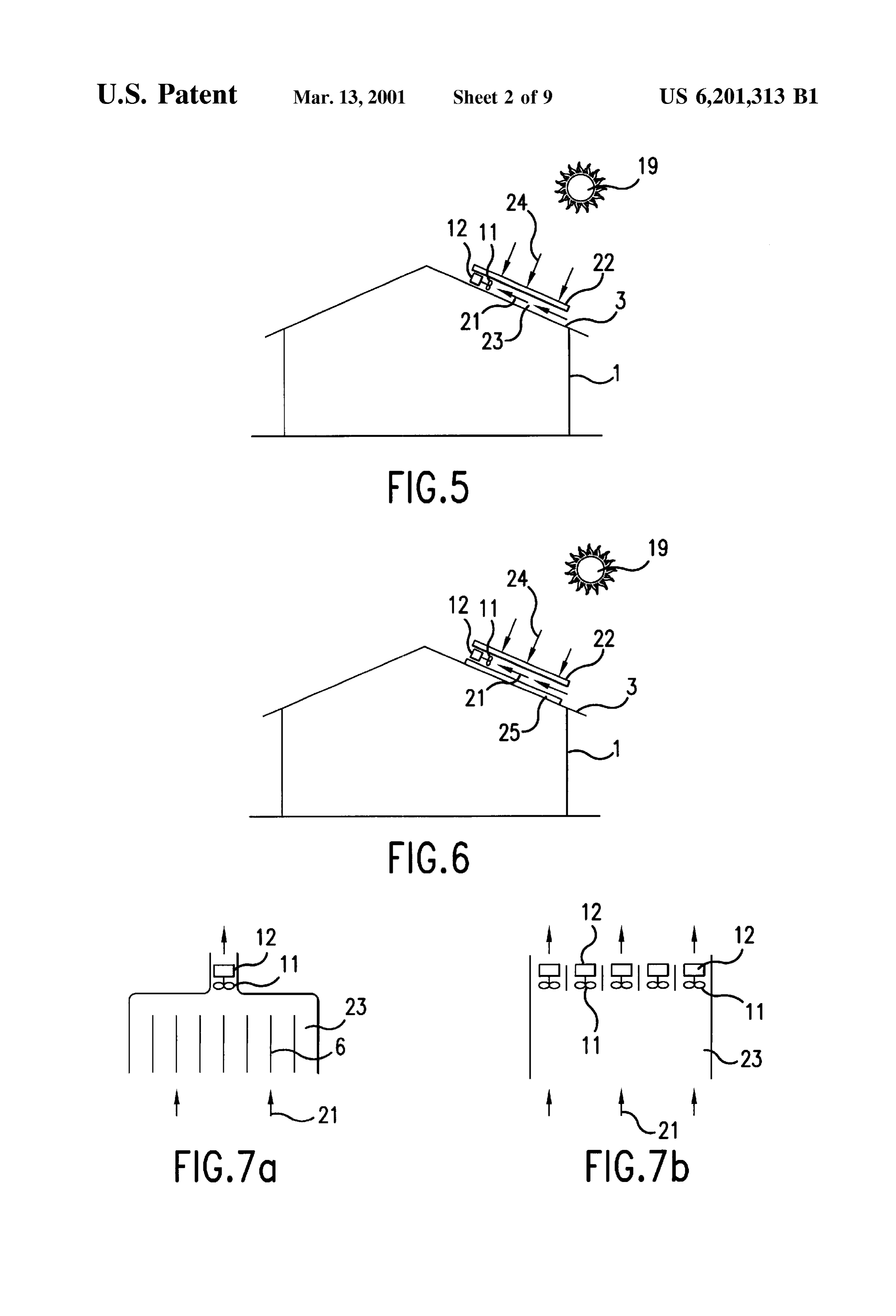
economically converts convectional flow into useful energy. FIG. 7a is a schematic partial plan view of the embodi It is yet a further object of the invention to utilize ments of FIGS. 5 and 6;
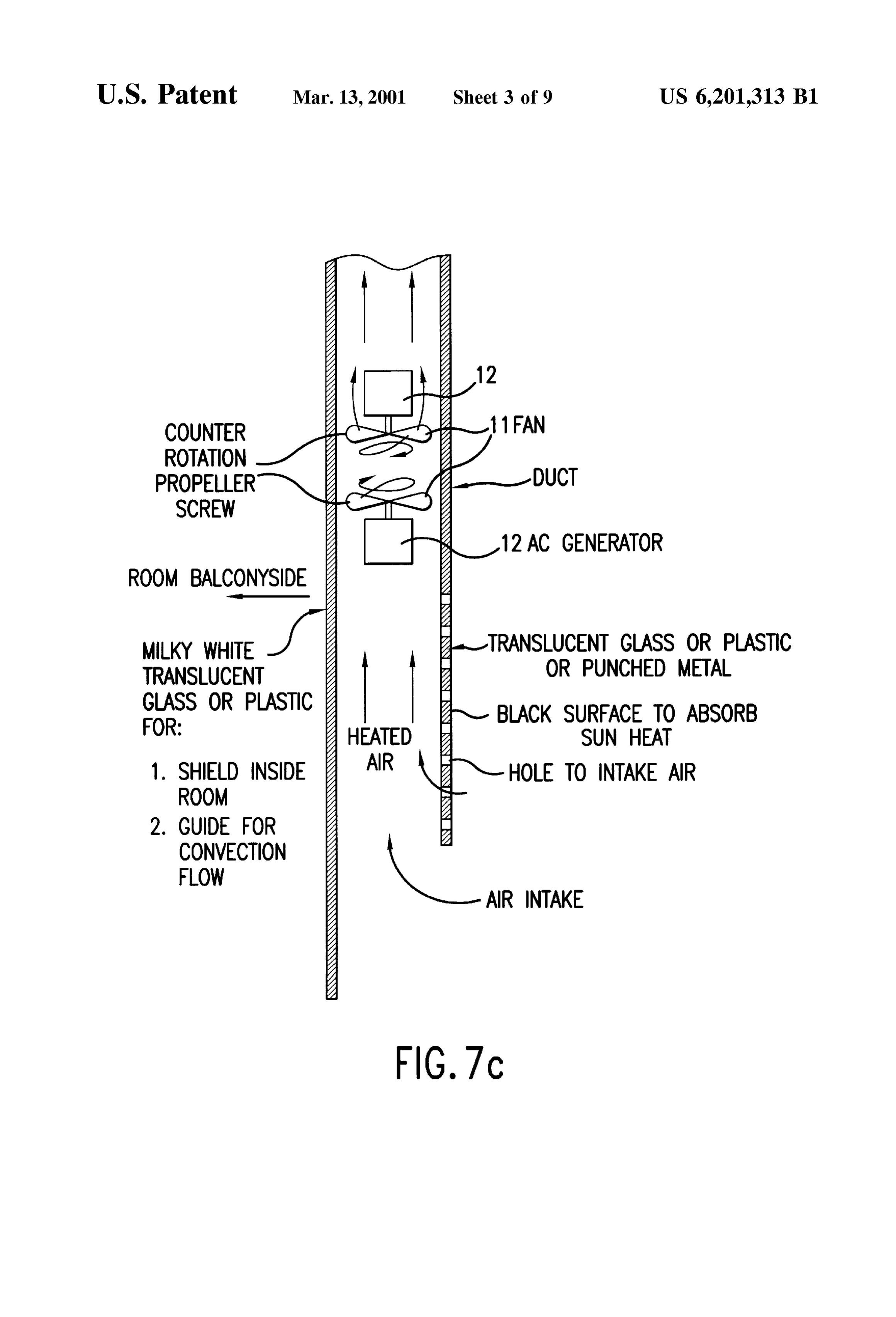
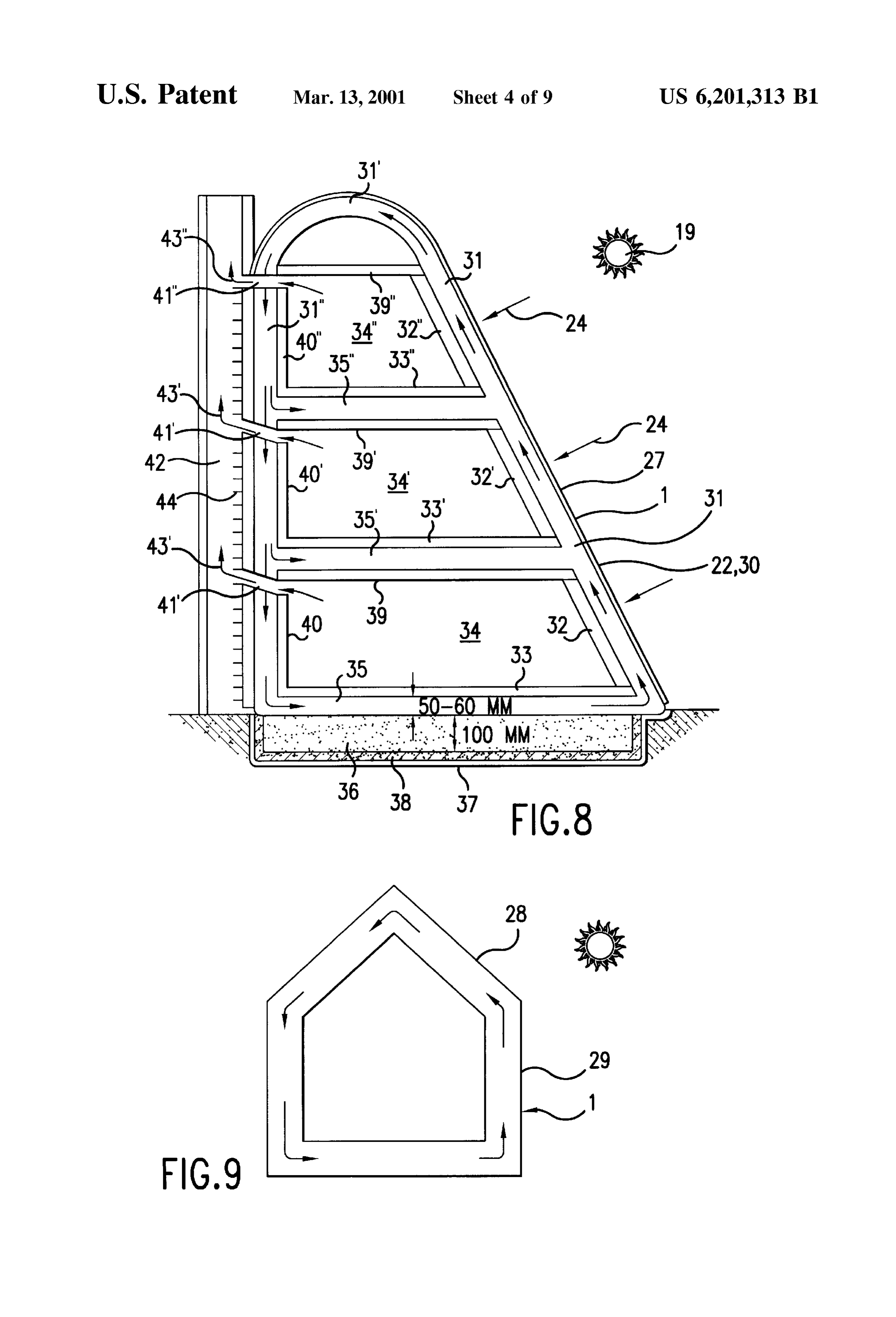
convection of fluid by connecting both portions high and FIG. 7b is a schematic partial plan view of the embodi low in temperature to each other, or operating on the ments of FIGS. 5 and 6 utilizing laterally disposed multiple chimney effect and high temperature obtainable from Solar fan-operated generators, heat, air-conditioning heat, cooking heat, body heat, general living heat, etc., and produce useful electrical and/or theFIG. 7c is a schematic longitudinal view of a variation of embodiments of FIG. 7a, mechanical energy, ventilation energy and other energies therefrom. FIG. 8 is a Schematic longitudinal cross-section of a Sixth 35 embodiment of a convection energy generating System in
SUMMARY OF THE INVENTION accordance with the invention;
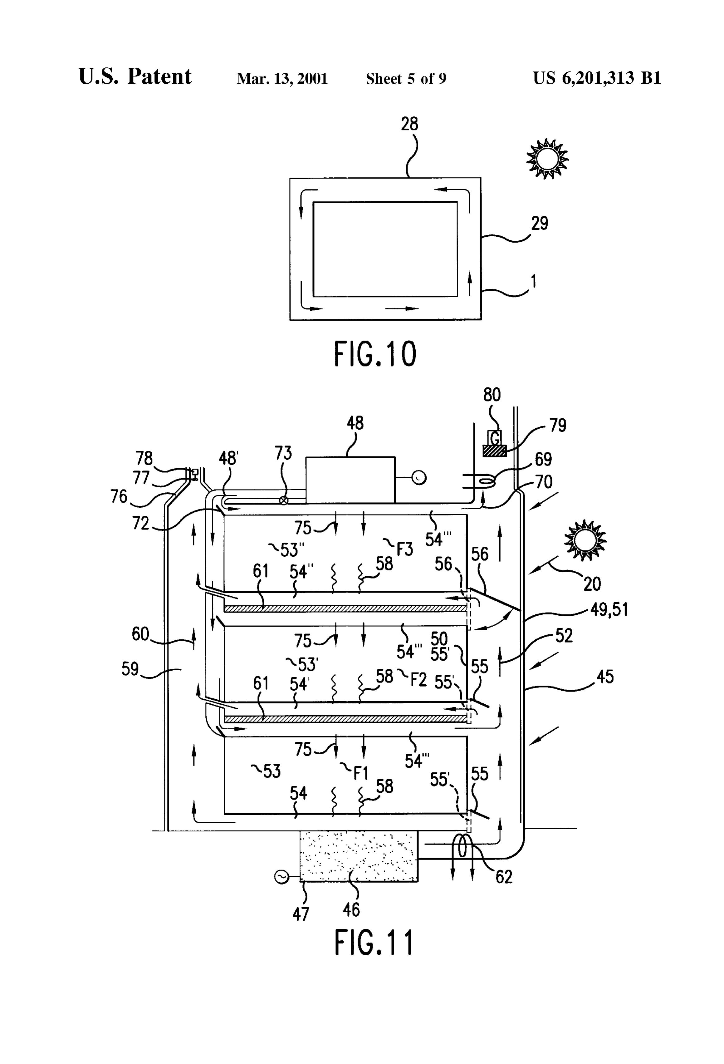
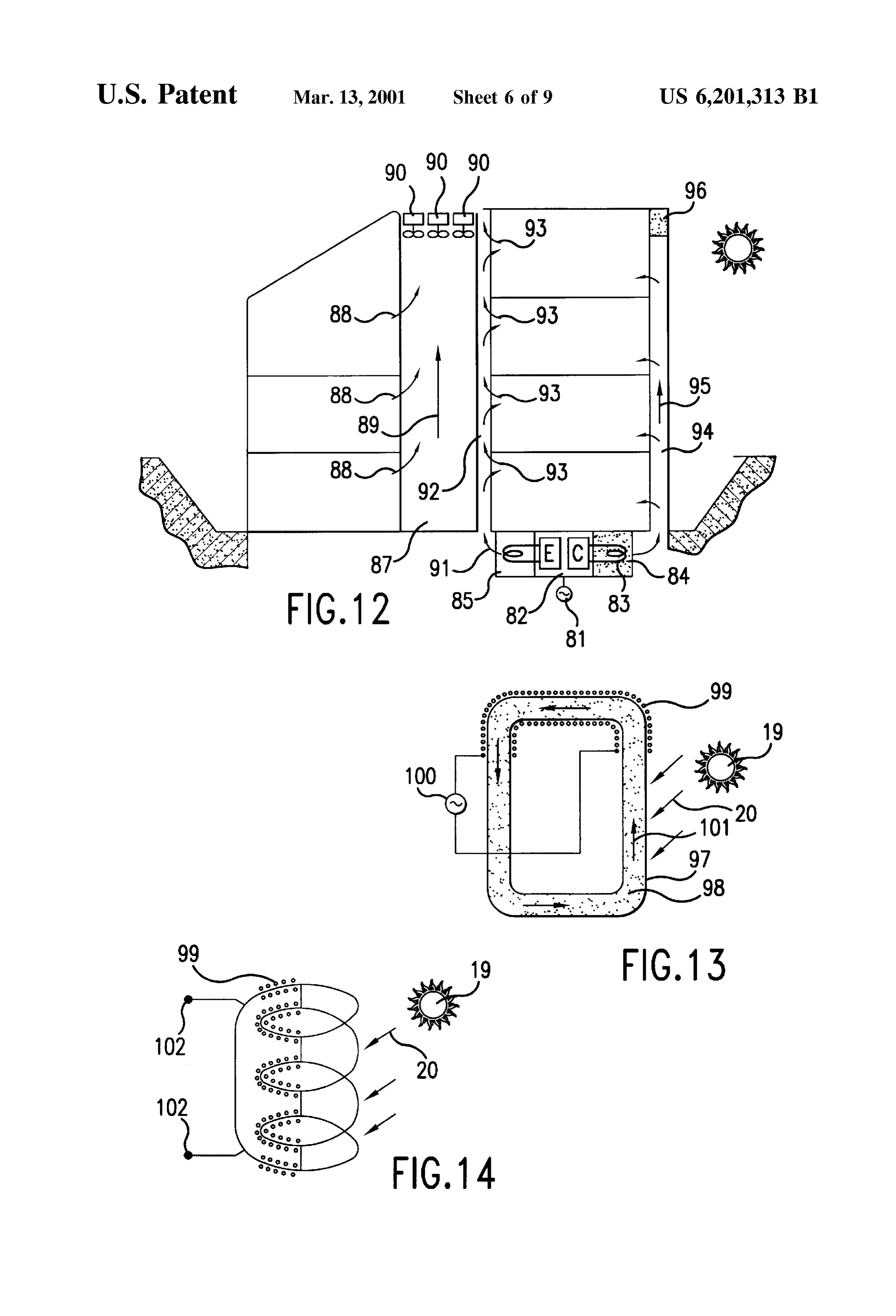
Briefly Stated, the present invention provides an energy FIG. 9 is a Schematic longitudinal croSS-Section of a generation System which utilizes convection flow of a fluid Seventh embodiment of a convection energy generating media caused by differences in temperature to generate 40 System in accordance with the invention; useful energy therefrom. A conduit for directing convection FIG. 10 is a schematic longitudinal cross-section of a circulation is provided for permitting conversion of forces eighth embodiment of a convection energy generating Sys associated with the movement of the fluid media in the tem in accordance with the invention; conduit into a usable energy by its effect on a generation FIG. 11 is a Schematic longitudinal cross-section of a device as the fluid media flows past Such device. 45 ninth embodiment of a convection energy generating System In accordance with various embodiments directed to use in accordance with the invention; in generating electrical energy in a home environment or FIG. 12 is a Schematic longitudinal cross-section of a other building Structure, the energy generation System com tenth embodiment of a convection energy generating System prises a conduit into which is vented heated air from the in accordance with the invention;
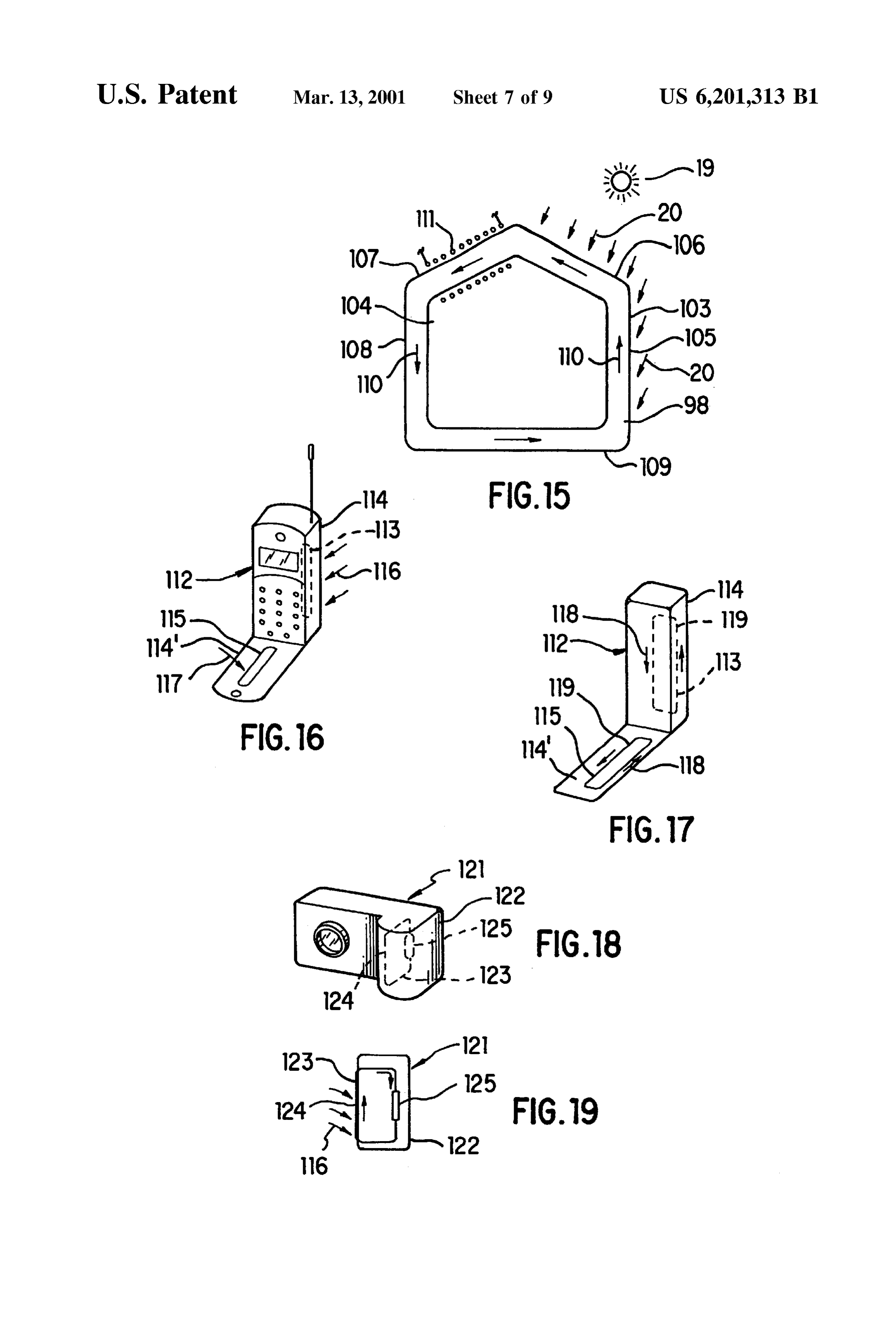
interior of the Structure. The conduit is open to the outside 50 FIG. 13 is a Schematic longitudinal cross-section of an at a top thereof, Such that by Virtue of the chimney effect, an eleventh embodiment of a convection energy generating upwardly rising Stream of air within the conduit is produced System in accordance with the invention; by convection. A fan-operated generator placed in contact FIG. 14 is a schematic view of the pipe conduit of a with the Stream of air produces usable electricity. twelfth embodiment in accordance with the invention; In alternative embodiments also directed to electrical 55 generation for various building Structures, the conduit thirteenth FIG. 15 is a schematic view of the pipe conduit of a embodiment in accordance with the invention;
referred to above for channeling a stream of convected air is FIG. 16 is a perspective view of a fourteenth embodiment placed external of the building and is heated by Solar rays in accordance with the invention; which create the flow of air within the conduit.
In further embodiments, directed to use in connection 60 FIG. 17 is a Schematic representation of the fluid passage with building Structures as well as hand-held applications, of FIG. 16;
Such as for example in cameras and cellular phones, instead FIG. 18 is a perspective view of a fifteenth embodiment of employing air, a magnetic fluid is used to conduct in accordance with the invention;
convention forces. Energy is generated by a coil wound FIG. 19 is a schematic representation of the fluid passage about a continuous enclosed conduit in which the fluid is 65 of FIG. 18;
made to circulate, and which generates electricity by Flem FIG. 20 is a plan view of a sixteenth embodiment in ing's right hand rule. accordance with the invention;
Page 12
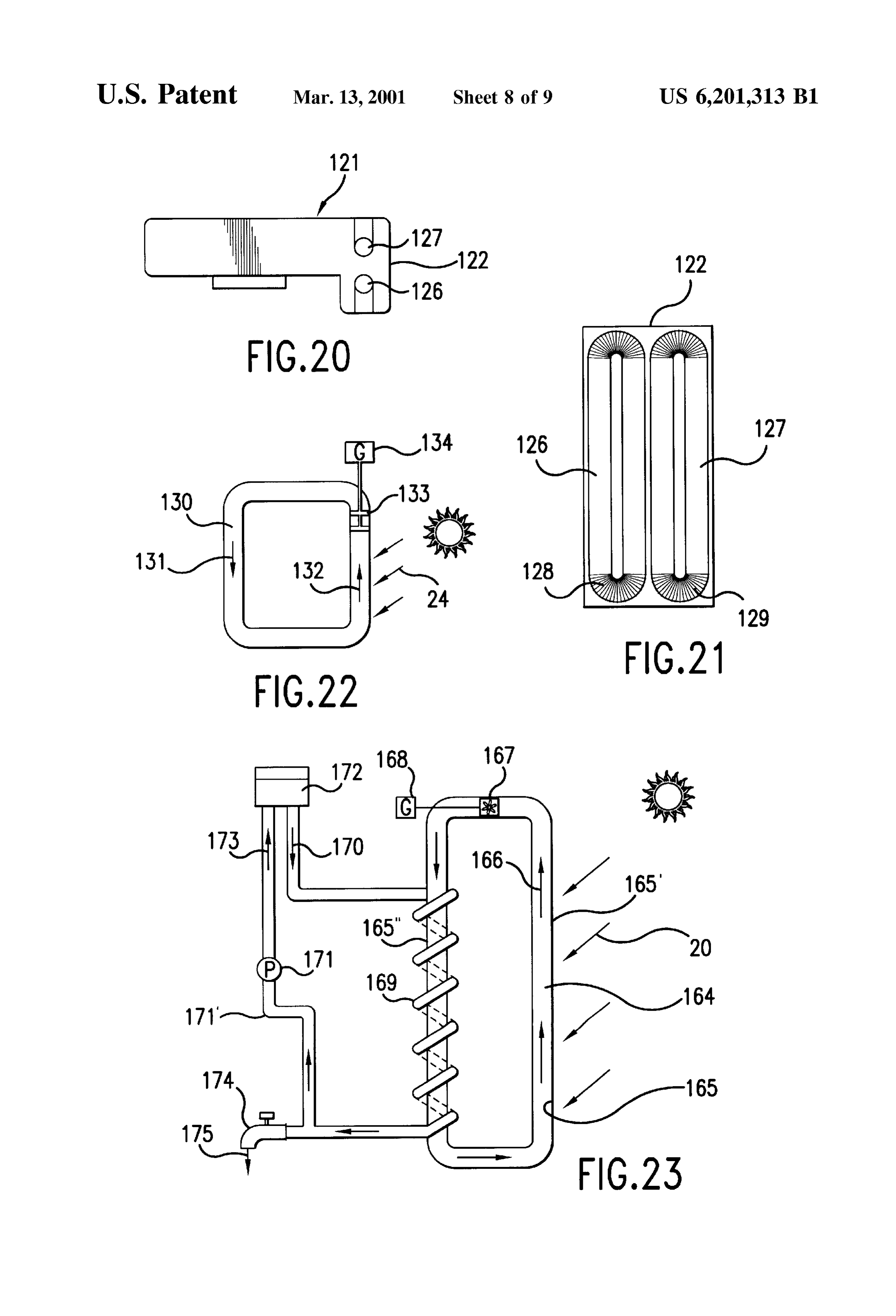
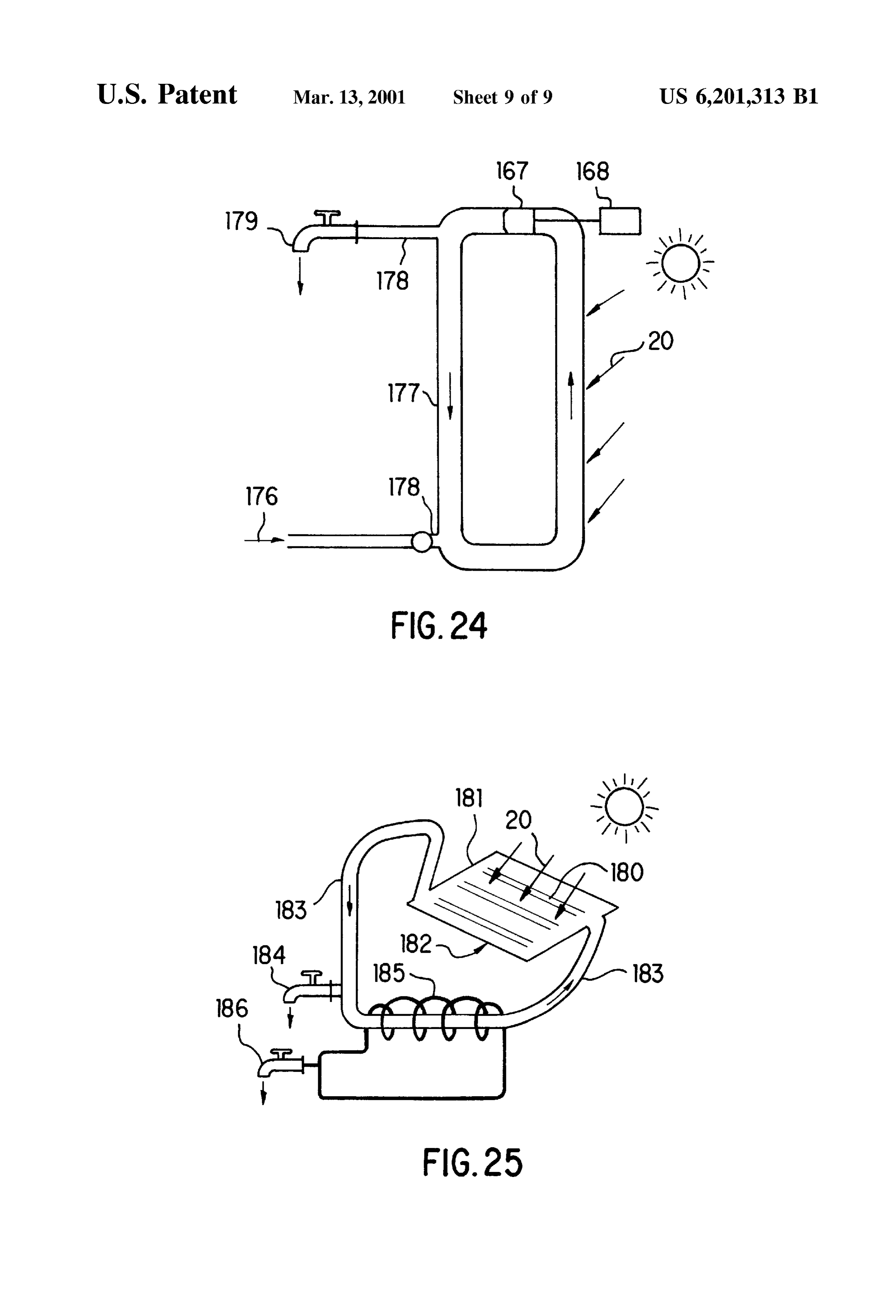
FIG. 21 is a side view of the embodiment of FIG. 20, placed along an outer wall 17 and a roof 3 of building showing the fluid passage; structure 1. Power generator 12 with fan 11 are provided FIG. 22 is an elevational Schematic representation of a within passage 18 proximate a top end thereof. pipe conduit of a Seventeenth embodiment in accordance When passage 18 is heated by solar rays 20 of the sun 19, with the invention; a rising air Stream 21 is generated by heat effects within FIG. 23 is an elevational Schematic representation of a passage 18 which turns fan 11 to yield power generation. A pipe conduit of an eighteenth embodiment in accordance Suitable form for fan 11 includes, for example, propeller-fan, with the invention; croSS-flow-fan, Sirocco-fan, etc. FIG. 24 is an elevational Schematic representation of a Passage 18 can be built as part of building structure 1, or pipe conduit of a nineteenth embodiment in accordance with can alternatively be Sold as a separate adaptor to be attached the invention; and to completed construction. Optionally, heat efficiency is FIG. 25 is a Schematic representation of a pipe conduit of advantageously enhanced by inclusion of a fin (not shown) a twentieth embodiment in accordance with the invention. having a large heat absorption capability, attached to the
Surface of passage 18 or where the Surface is treated for
DETAILED DESCRIPTION OF THE enhanced heat absorption.
INVENTION Turning now to FIG. 5, an embodiment of the invention Referring to the figures, and in particular FIG. 1, an is depicted in which a solar battery 22 is installed on roof 3 embodiment of a convection energy generating System in of building structure 1, and both sides of Space between roof accordance with the invention is depicted, directed to use in 3 and Solar battery 22 are enclosed to create a hollow ventilating a living Space and converting air convection passage 23. AS in the previously described embodiments, caused by environmental heat produced in a house, includ power generator 12 and fan 12 are installed advantageously ing for example body warmth and artificially created heat, at or near the top end of passage 23.
into useful energy. A conduit 4 in the form, for example, of When light 24 of the sun 19 shines on Solar battery 22, an exhaust pipe or a chimney, Stands vertically, advanta 25 electric power is obtained directly therefrom, and at the geously at the center of building structure 1, and extends Same time battery panel 22 is heated by the Sun. As a result, through room 2, ceiling 2" and roof 3. Conduit 4 includes hollow passage 23 is also heated to produce rising air Stream holes 6 and 6' near ceiling 2" of room 2. 21 by the chimney effect. This air Stream is gathered together Warm convection 9 of heat produced by heating of room by means of air circuits, as will be more fully described with 2 by artificial sources and body heat is drawn into conduit 4 reference to FIG. 7, and turns fan 11 to generate electricity. through holes 6, 6' and once inside comprises a rising air By changing Sun light to electricity through Solar battery 22 stream 10 created by the chimney effect. Rising stream 10 and power generator 12 operated by Solar heat, and therefore turns a fan 11 near the upper top of conduit 4, which in turn making more complete use of Solar energy, it is possible to operates a power generator 12 drivably connected therewith. obtain electric power with improved thermal efficiency. In this manner electric power can be obtained from power 35 Referring now to FIG. 6, an embodiment of the invention generator 12 by warm convection 9. is shown which employs triple construction power generat Conduit 4 can provide Several advantages concomitant ing equipment for further utilization of the potential of the with its usefulness in channeling rising Stream 10 upward for Sun. In addition to solar battery panel 22, a hot-well 25 is purposes of energy generation. One advantage gained is that placed on roof 3 and enclosed to create a hollow passage in conduit 4 naturally provides improved ventilation to room 2 40 a manner analogous to the embodiment of FIG. 4. Rising air by operation of the chimney effect. Other advantages are Stream 21 produced between Solar battery panel 22 and attained in various optional embodiments. In one Such hot-well 25 turns fan 11 of power generator 12. This advantageous embodiment, conduit 4 may be made Struc integrated System, combining three forms of Solar energy turally Supportive to function as a post in part of building generation, maximizes use of the Solar energy potential. In Structure 1. In an alternative embodiment, where desired, 45 particular, radiant energy from the Sun 19 is used Simulta conduit 4 may be made partially transparent by glass, etc., neously for generation of electric power by Solar battery thus functioning as a light court to Supplement the lighting panel 22, generation of Supplementary electric power by of room 2. In yet another embodiment, conduit 4 may form operation of power generator 12 by convected rising air a central Support for a spiral Staircase 5, thereby improving stream created by the heat of the Sun 19, and Solar heat the efficient use of Space in house 1. 50 warming of water by hot well 25. An optional Small roof 7 is provided at upper opening of FIG. 7a shows a top view of hollow passage 23 under conduit 4 to prevent the penetration of rainwater therein. It Solar battery panel 22 in the embodiments shown in FIGS. is noted that where conduit 4 functions as a light court, as 5 and 6, wherein passage 23 is partitioned with Separating referred to above, small roof 7 should preferably be clear or panels to create multiple converging air circuits which light transmissive. If small roof 7 is omitted, fan 11 rotates 55 consolidate and direct rising air Stream 21 to fan 11 of power to force away rain and Simultaneously generate electricity. A generator 12.
lid may be optionally provided at the upper part of conduit The embodiment of FIG. 7b utilizes multiple, laterally 4, for purposes of Selectively stopping rising Stream 10, disposed fan/generator pairs 11, 12.
when necessary. The croSS-Sectional dimensions of conduit FIG. 7c illustrates a variation of the previous embodiment 4 will determine the conforming shape of the lid, for 60 of FIG. 7a , wherein two fan/generator pairs 11, 12 are example, Square, rectangle, triangle, etc. placed in-line for counter-rotation. A one side of passage 23 FIGS. 2 and 3 depict a second embodiment in accordance is defined by a milky white translucent material, and the with the invention. Steam and hot air in a bath room 13, and remaining side (illustrated by dashed lines) is a black unpleasant odors 16 in a lavatory 15, are vented and punched metal.
exhausted by rising stream 10 in conduit 4. 65 FIG. 8 shows an example in accordance with another FIG. 4 shows an embodiment of the invention wherein a embodiment of the invention wherein the energy generation passage 18 of black Square pipe or round pipe, etc. are System is applied to a building in which circulation type
Page 13
S 6 air-conditioning is installed. It is believed to be approxi and inner wall 50, or 2-ply glass plate 51, 51". A door 56 is mately 15% more efficient to lean the southern side of attached to top room 53", door 56 being of Sufficient width building Structure 1 at an angle of 30 degrees, as shown in to close the space between outer wall 49 and inner wall, or FIG. 8, however it is nonetheless also possible to face a 2-ply glass plate 51, 51". In the winter season, each door usual sloped roof 28 and a vertical wall 29 to the South, as opens as shown by 55 and 56, and closes as shown by 55 shown alternatively in FIG. 9. Building structure 1 can be and 56' in the Summer season.
also be square as shown in FIG. 10. Solar battery panel 22 Since each door opens in the winter Season, heat convec or glass, metallic plates, etc. are attached to Outer wall 27 tion caused by solar heat within 2-ply wall 51, 51' warms up and inner walls 32, 32", 32" of building structure 1. Air the space under floors 54, 54, 54" on each level, and each passage 31 rises up, turns at position 31', descends at room is warmed by hot air 58 entering from below. The position 31" and passes under floors 33, 33', 33" of rooms convection coming from between 2-ply wall 51, 51 34, 34, 34", and turns to position 31, so that air circulates in becomes a rising air stream 60 at a chimney 59, and draws air under the floors to continue the flow of hot air to the passage 31. Inner walls 32, 32", 32" of building structure 1 rooms. A heat insulating layer 61 is Set to thermally divide work Sufficiently well as heat insulating material to protect the warming Space below the floor and a cooling Space rooms 34, 34, 34" from Solar heat, while at the same time 15 inhibiting the escape of heat from air passage 31. Light rays above the ceiling of the room below, mutually from one another. Chimney 59 can take the form of a pipe or conduit from the sun 19 are changed to electricity by Solar battery 4 of FIG. 1, and can utilize any of the aforementioned panel 22, and Solar heat warms up air within air passage 31 approaches, Such as its Secondary use as a light court. by convection. Where solar heating provides insufficient warmth, forced Floor 33 of room 34 at the first story is made of wood, and hot air is Supplied from underground heat Storage Source 47. a space of about a 50 mm to 60 mm in thickness is made Aheat eXchanger 62 is also provided for purposes of making between floor 33, and 100 mm thick concrete ground 36 is hot water, and Supplies hot water within building. deposited beneath air passage 35. The weight of building In the Summer season, doors 55 and 56 are closed at Structure 1 rests upon concrete 36, which is also used for positions 55' and 56', and the air heated by Solar rays 20 heat Storage. Use of inexpensive concrete results in lower 25 flows upwardly through via rising air Stream 52 caused by cost. For example, if reclaimed concrete obtained by convection, and does not enter the space under floors 54, 54, destruction of concrete building or a new low cost cement 54". During this time, heat convection 52 is still used to heat called “Ecological Cement” (which is made of ashes water via another heat exchanger 69 for Supply of hot water reduced from refuse, limestone, etc. without producing to the building. Also, rising air Stream 52 caused by this dioxin) is used instead of concrete 36, expense for the convectionthe arrow draws air in ceiling 54" to the direction shown by designated by the numeral 70.
installation of this layer is reduced. In the Summer, door 72 opens in response to the opening Prior to laying the concrete, damp-proof plastic film sheet of a valve 73 which sends cool air 48" from freezer 48 37, Such as polyethylene, is first applied, and then heat (placed on roof and operated by night Service power) to insulating material 38 is put on plastic film sheet 37. 35 above each ceiling and cool spaces F1, F2, F3 of rooms 53, Concrete 36 is then deposited atop heat insulating material 53, 53" cooled by cool air 75 coming from above the 38. ceilings. Cool air 75 is drawn to the direction of 70 and a Space 35 comprises a portion of the circulating route in air fresh inflow of cool air 48" from freezer 48 is sent in. passage 31 and, in a Similar manner, SpaceS 35', 35" are Electricity is generated by operation of a vertical axis type made respectively under floor 33' on the second story and 40 generator 78 rotated by horizontal fan 77. The top end of floor 33" on the third story to join air passage 31. Ceilings chimney 59 is narrowed into a tapered shape 76, to concen 39,39', 39" and walls 40, 40', 40" are made of heat insulating trate air stream 60 coming from below. material.
Since the Space between 2-ply wall layer on the Southern
Air ducts 41, 41', 41" are provided near the ceiling in each Side of the building is comparatively narrow between walls room and lead to chimney 42. Chimney 42 vents exhaust 43, 45 while being expansive widthwise, a horizontal turning type 43', 43" from rooms 34,34, 34" by the chimney effect. If an fan 79 is placed at top space of 2-ply wall layer to obtain emergency Stairway 44 is built within chimney 42, the Space power generation by operation of a horizontal type generator factor is improved accordingly. If a transparent chimney 42 80 rotated by rising air stream 52 which turns fan 79. is built indoors, it can be used as light court. As a Support, Turning now to FIG. 12, an energy generation System in chimney 42 can also help to resist against Side quake. It is 50 accordance with another embodiment of the invention is also possible to apply chimney 42 to conduit 4 shown in depicted. Machines operated by night Service power for cold FIG. 1. Storage located on the roof and heat Storage in the basement FIG. 11 shows an example of an air conditioning System. of FIG. 11 are combined into one unit. The combined unit, Ecological cement (described above) is deposited under in the form of a cooler 82, is advantageously operated by ground as a cement layer 46, below a building 45. Cement 55 night Service power 81. Heat is Stored in heat Storage Source layer 46 is heated by a heater (not shown) advantageously 84, Such as a Slab of ecological cement, transferred thereto using less expensive night Service power, and works as a via a water filled radiator 83 of condenser C of cooler 82. A heat storage 47. freezer 85 is operated by evaporator E of cooler 82 without Freezer 48, also advantageously operated by night Service requiring use of the roof, while concomitantly providing power, is set on the roof of building 45. The Southern side 60 better cooling. Cooler 82 can be installed underground for of building is heated by solar rays 20, which in FIG. 11 is better maintenance of cold Storage. A hollow pole 87 making shown as the right Side. This side has a glass plate or Solar use of the Structure of the building encloses a rising air panel on an outer wall 49 and an inner wall 50, or a 2-ply stream 89 produced from indoor cooking, electric glass plate 51,51'. Heat convection fluid 52 rises up between appliances, human body temperature, etc., within hollow outer wall 49 and inner wall 50. A door 55 is attached to the 65 pole 87, which operates a plurality of wind power generators Southern side under floors 54, 54 of rooms 53, 53'. The 90 placed downward at an outlet on the top of hollow pole width of door 55 is about/3 the space between outer wall 49 87.
Page 14
Cool air 91 coming from underground cooler 82 is drawn Referring now to FIG. 22, an embodiment in accordance into each room replacing the warm air leaving the rooms as with the invention is depicted in which solar rays 24 shine exhaust 93. Warm air coming from radiator of cooler 82 in on part of a circuit 131 in which water 130 or other fluid the basement is Supplied to each room by rising air Stream media is contained for circulating flow therein and heating 95 within a 2 ply wall layer 94 on the southern side. A heat Same up, thereby creating circulation by heat convection in Storage apparatus 96 is provided, throughout which a Snake the direction of arrow 132. A power generator 134 is shaped pipe for carrying air or water is placed to permit provided to generate electricity in response to the water production of hot air or warm water, and which becomes a turbine 133 installed in circuit 131 and turned by the thermal Source for Such requirements as heating, hot water circulating fluid.
Supply, etc., at night and cloudy weather. FIG. 23 illustrates an embodiment in accordance with the FIGS. 13 to FIG. 21 are directed to various embodiments in accordance with the invention, wherein magnetic fluid invention wherein part 165' of closed pipe 165 which is which moves magnetism in circulation, rather than convec advantageously of externally black in color and in which a tion of air, is used for energy generation. thermal media 164 such as water, FREON, etc., is heated up Referring to FIG. 13, an embodiment of the invention by Solar rays 20. Heated thermal media 164 rises by heat includes a closed pipe 97 filled with a magnetic fluid 98, for 15 convection to circulate in the direction of arrow 166 and instance, a fluid containing magnetic particles which are operates power generator 168 by turning turbine 167. A coated and dispersed in oil without coagulation, A coil 99 is thermal eXchange pipe 169 is wound around closed pipe wound on part of circulating passage of closed pipe 97 to get 165" on the opposite side to the heated side. When cool a power source 100 from the end of coil 99. water 170 is supplied to heat exchange pipe 169, cool water Recently, it has been discovered that water or petroleum 170 is heated, and at the same time thermal media 164 is products react to a magnetic field, enabling water and the cooled down. Cooled fluid 164 descends and is heated up by selected petroleum product to function as magnetic fluid 98 Solar rays 20 to rise and circulate.
in the circulating passage of closed pipe 97. When Solar rays Water 170 within thermal exchange pipe 169 is heated up 20 of the Sun 19 shines on pipe conduit 97, heating same, 25 through water 173 which is pushed up to a water tank 172 fluid 98 moves by convection running within closed pipe by pump 171, and hot water 175 is supplied from cock 174. conduit 97 in the direction of arrows, and electric current is Pipe 171" is provided to increase the temperature of water generated within coil 99 by Fleming's right hand rule. within tank 172 by returning unused water to tank 172 by Referring to FIG. 14, an embodiment of the invention is pump 171.
depicted, wherein the above described closed pipe conduit is Turning now to FIG. 24, an embodiment is depicted in formed to the shape of a coil 99, and coil 99 is wound on part which a direct heating method is employed. Water 176 is of the closed pipe conduit to efficiently obtain electric supplied from lower part 178 of a closed pipe 177 by current from a power Source 102 tapped at opposed ends of preSSure of city water without the need for installing pushing coil 99. pump 171 and water tank 171 of the previously described FIG. 15 illustrates an embodiment of the invention in 35 embodiment shown in FIG. 23. After water 176 is heated up which a circuit 103 is attached to a house 104. Pipe conduits by Solar rays 20 and rises to turn turbine 167 of power 105 and 106 of circuit 103 are placed on the wall and roof generator 168, hot water is supplied from cock 179 of a on the southern side of house 104 which is impinged by solar junction pipe 178.
rays 20 of the Sun 19 (as indicated by the plurality of arrows) FIG. 25 illustrates an embodiment in accordance with the and pipe conduits 107, 108 and 109 are attached to the roof, 40 invention, wherein Solar rays 20 are received by a panel side wall and under the floor not lit by the sun 19. As a result, consisting of a thin glass box 181 containing water pipes 180 the temperature difference of the various pipe conduits 105, or a hot well kept warm by inserting water pipes 180 into a 106, 107, 108, 109 makes magnetic fluid 98 flow in the Vacuum glass pipe, and in which a cock 184 is fixed directly direction of arrow 110 within circuit 103 and electricity is to closed water pipe 183 to obtain hot water. Where a fluid obtained by a coil 111. 45 with a low boiling point, Such as Freon, etc. is used instead FIG. 16 and FIG. 17 depicts an embodiment in accor of water, a heat eXchange pipe 185 is wound on closed water dance with the invention wherein circulating pipe conduits pipe 183 to heat up water in heat exchange pipe 185 in order 113 and 15 filled with magnetic fluid are set on a body 114 to get hot water from cock 186. Turbine 167 of power of a cellular phone 112 and a flipper 114", respectively, and generator 168 can optionally be fixed to pipe conduit 183 for generate electricity for cellular phone 112. Since heat 116 of 50 power generation.
the hand holding cellular phone 112 warms part of pipe Air, Water, Streaming magnetic material, oil, Steam, etc. conduit 113 on a body of same held by the hand, and since can all be used for fluid in accordance with the intended also the heat of breadth 117 generated by the user while Scope of the invention. The Pipe used for passing fluid is Speaking warms pipe conduit 115 on flipper 114", convection advantageously black and rough in Surface to improve heat 118 of the magnetic fluid is produced, coil 119 thereby 55 absorption, and also advantageously has fins to improve yielding electric power as a power Source for cellular phone radiation and to obtain a larger temperature difference, So 112. that convection Speed can be increased. FIGS. 18 and 19 illustrate an embodiment in accordance If electric power obtained by the examples of the embodi with the invention wherein a circuit 123 containing magnetic ments Set forth above is arranged to charge a battery, or to fluid, a heat absorbing part 124 thereof, and coil 125, are set 60 be reduced to daytime energy by ice-making, or warm water on a griping part 122 of a camera 121. is arranged to pass through heat Storage material, it is FIGS. 20 and 21 depict an embodiment in accordance possible to continuously use electric power and warm water with the invention wherein two lines of circuits 126 and 127 even at night, and also Surplus power can be Sold to a power are Set in griping part 122. A thumb of the hand warms company to earn income.
circuit 127 and the other four fingers transfer heat to heat 65 The unique and ground breaking invention described absorbing part 126, So that electric current as a power Source herein will have world-wide as well as region-wide benefits for camera 121 is obtained from coils 128 and 129. in making use of warm air usually wasted, and will further
Page 15
increase efficiency of thermal energy. In this regard, the wherein, Said conduit has at least one opening at a lower invention will provide energy to any country short of point to an interior Space of Said building Structure as national resources in a manner non-polluting to the envi an intake of a heated air of the building. rOnment. 2. An energy generation System, comprising: Having described preferred embodiments of the invention a conduit for channeling a convected flow of an air created with reference to the accompanying drawings, it is to be by a difference of heat along portions of Said conduit; understood that the invention is not limited to those precise an energy generation means responsive to Said flow of air embodiments, and that various changes and modifications disposed along Said conduit for converting energy of may be effected therein by one skilled in the art without Said air flow into another form of a uSable energy; departing from the Scope or Spirit of the invention as defined 1O in the appended claims. wherein, Said conduit is attached to a building Structure What is claimed is: with a portion of Said conduit oriented vertically and 1. An energy generation System, comprising: having an opening at a top;
a conduit for channeling a convected flow of an air created 15 wherein, a heated air vents into an outside environment by a difference of heat along portions of Said conduit; through said conduit by a chimney effect of Said an energy generation means responsive to Said flow of air convected flow;
disposed along Said conduit for converting energy of wherein, Said building Structure has a floor and a Space Said air flow into another form of a uSable energy; juxtaposed to the floor, Said conduit directing heated air wherein, Said conduit is attached to a building structure to Said Space to thereby heat Said floor; with a portion of Said conduit oriented vertically and wherein, Said energy generation means consist of a fan having an opening at a top; operated electrical generator positioned in Said con wherein, a heated air vents into an outside environment vected flow within said conduit; through said conduit by a chimney effect of Said wherein, Said conduit is a part of a Solar heating System convected flow; 25 attached to Said building Structure with a Solar panel wherein, Said energy generation means consist of a fan positioned at an exterior of Said building Structure to operated electrical generator positioned in Said con define a portion of Said conduit; vected flow within said conduit; wherein, Said conduit has at least one opening at a lower wherein, Said conduit is a part of a Solar heating System point to an interior Space of Said building Structure as attached to Said building Structure with a Solar panel an intake of a heated air of the building. positioned at an exterior of Said building Structure to define a portion of Said conduit; k k k k k
Provenance
- Collection
- Cited prior art
- Original PDF
- patentimages.storage.googleapis.com →
- Filed
- 1998-10-05
- Pages
- 15
- Method
- pdftotext (the PDF's own text layer) + pdftoppm 300dpi page scans
- Source
- Google Patents bibliographic record
- Granted
- 2001-03-13
- Inventors
- Yoshiro Nakamats
- Transcribed from
- patentimages.storage.googleapis.com →