patent · US2510800
Method and apparatus for producing electrical and mechanical energy from thermal energy
6 June 1950
Page 1 — bibliographic record
June 6, 1950 METHOD AND APPARATUS
C. CHLOWSKY
FOR PRODUCING ELECTRICAL
AND MECHANICAL ENERGY FROM THERMAL ENERGY
Filed Nov. 10, 1945 3 Sheets-Sheet l
S. & SSES
INVENTOR,
dean - Chua'
4T ZOANAYS
Page 2
Drawing sheet — no readable text.
Page 3
Drawing sheet — no readable text.
Page 4
Patented June 6, 1950
METHOD AND APPARATUS FOR PRODUCING
ELECTRICAL AND MECHANCAL ENERGY
FROM THERMA, ENERGY
Constantin Chilowsky, New York, N.Y.
Application November 10, 1945, Serial No. 627,832
This invention relates to a method and ap 2 paratus for producing electrical and mechanical accompanied by the appearance and disappear energy from thermal energy. ance of its magnetic properties (permeability), It is known that paramagnetic bodies, and par causes the magnetic resistance of the ring and the ticularly the ferromagnetic bodies, such as iron, cally magnetic flux flowing through it to vary periodi nickel, cobalt and certain special alloys (charac to a great extent. This induces a magneto terized by great magnetic permeability), keep the Windingforce motive and an alternating current in the of the ring. If necessary, a part of greater part of their magnetic properties up to this electric current can be used to produce Or to a certain critical temperature, called the Curie maintain the initial magnetic flux in the ring. point, and above this point become non-mag netic (or only slightly magnetic) on losing its 10 willPreferably, however, the initial magnetic flux be maintained in the ring by the use of a permeability. The temperature of the Curie point powerful permanent magnet. The two poles of for iron is 76.9° C., for nickel 360° C. and for cobalt such a magnet may be applied to symmetrical
The present invention has for its object a 5 points have of the magnetic ring, and the ring may two transverse sections for the heating, method and apparatus for the transformation of located at two points of the ring, symmetrical in thermal energy into mechanical, and particularly relation to the points of application of the poles electrical energy, by utilizing the above explained of the magnet.
phenomena, occurring in the neighborhood of The two interrupter sections are alternatively the Curie point.
Most particularly, the invention envisages the heated and cooled, with a phase difference of direct transformation of heat into electrical ener time between them of 180°. The magnetic flux gy without requiring-for the production of the furnished by the permanent magnet, in branching electric current--a mechanical movement. off between the semi-circles of the ring inversely The invention also provides for a special mode to their relative magnetic resistances, will tend to of heating and cooling the ferromagnetic matter, concentrate itself in the circuit of least resist through the intermediary of a metallic fluid in the ance, containing momentarily the section heated form of molten or liquid metal or alloy, or in the to a temperature below the Curie point. The form of metallic vapor. This mode of heating magnetic flux will thus pass from one branch of permits particularly to make this procedure com the ring to the other, and return, with the fre pact and commercially practical. The heating Sections, quency of the cycle of heating and cooling of the and cooling of the System by means of a metallic thus producing in the windings of the fluid and particularly of a metallic liquid has, as ring a two-phase alternating current. will be shown hereinafter, a very great advantage. Thus a generator of alternating electric cur According to the invention, the energy is trans rent is obtained, which is similar to existing formed into alternating electric current in a transformers, but with the difference that in the static transformer. For that purpose, a closed usual transformer the variation of the magnetic magnetic circuit is provided, for instance in super flux is produced by a primary electric current, imposed sheet-iron plates, as in an ordinary while in the new generator this variation of the flux is produced by the action of thermal energy, transformer. This closed magnetic ring includes 40 periodically varying or interrupting the flux. one or more transverse Sections or segments (con It is evident that on the basis of these prin sisting of the same or other ferromagnetic mate ciples it will be possible to produce also three rial) arranged in Such a manner as to be able to phase. Or multi-phase currents. be quickly heated and cooled by the passage of an The variations of the magnetic flux may be con appropriate fluid, now warmer, now colder, than 45 siderable. Thus, for instance, a total thickness of the Curie point.
This rapid variation of the section's tempera the interrupter section of 2 mm., heated above the ture, above and below the Curie point, produces a Curie point, is able to reduce the magnetic flux rapid variation of the magnetic resistance of down to one third of its initial value. the circuit. The heating and the cooling of the sections By means of a winding, through which flows an 50 will be effected, preferably, by two fluids, one hot (above the Curie point), the other 'cold' (below electric current developing a magnetomotive the Curie point), these two fluids acting alter force, an intense magnetic flux is induced in this natively on the Section.
iron ring. The periodic variation of the section's In principle, any fluid may be utilized for this temperature above and below the Curie point, 55 heating and cooling operation. For instance, the
Page 5
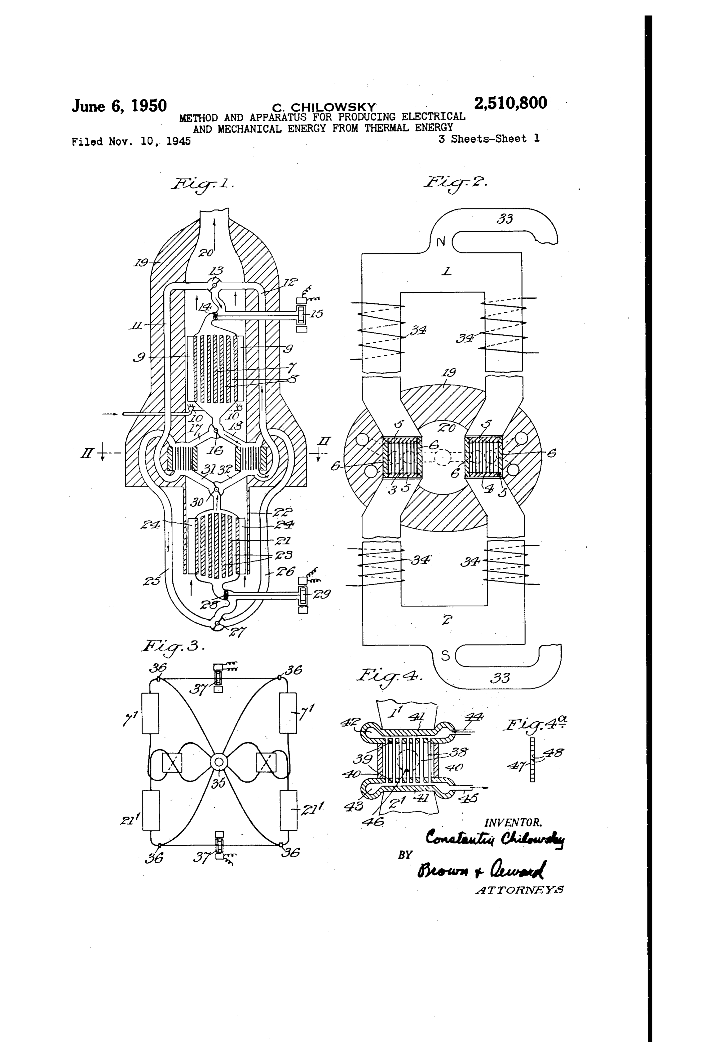
heating may be effected by the combustion prod in plan, taken on the line - of Fig. 1, or ucts of a fuel, and the cooling by air. But this an enlarged Scale;
will have the disadvantage of oxidation and of Fig. 3 represents diagrammatically a modified rapid destruction of the heating surfaces of the fiuid circuit arrangement; sections. Better heating and cooling results will Fig. 4 represents, in horizontal section, a de be achieved by circulating, in a closed circuit, a tail modification of the interrupter Section; fluid that is chemically inert and does not affect Fig. 4a represents, in section, a detail of part the heated metallic surfaces. In particular, the of an interruptersection;
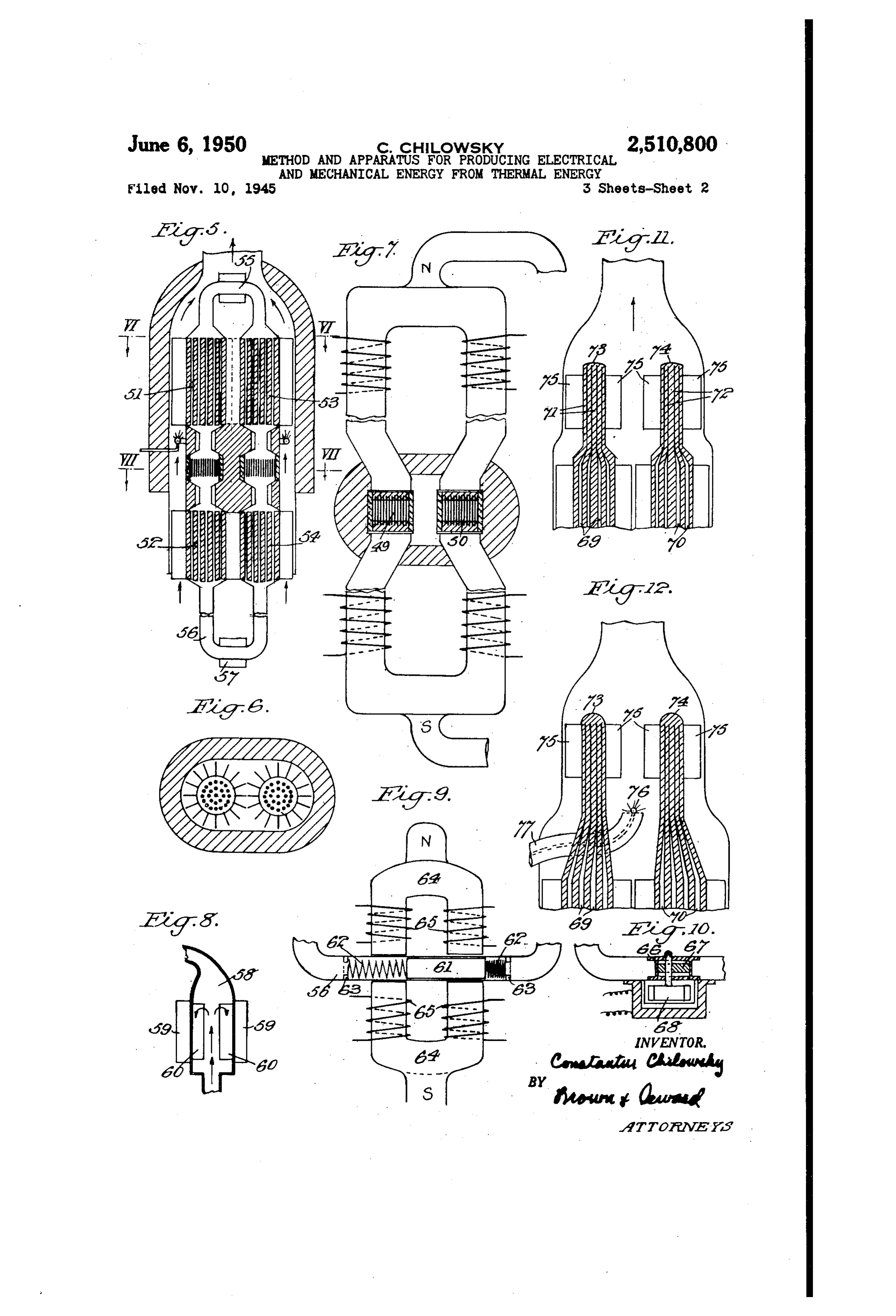
rare gases, such as helium, argon, neon, etc., Fig. 5 represents a vertical section, correspond may be used (under pressure). Such a gaseous O ing to Fig. 1, of a modified form of generator; fluid, used for the heating, may be heated by Fig. 6 represents a horizontal section, taken a fuel in an appropriate heat-exchanger, and on the line WI-VI of Fig. 5;
the fluid, used for the cooling, may be cooled by Fig. 7 represents a horizontal section, partly air or by water or simply by radiation in a heat in plan, corresponding to Fig. 2, taken on the exchanger. s line VII-VII of Fig. 5;
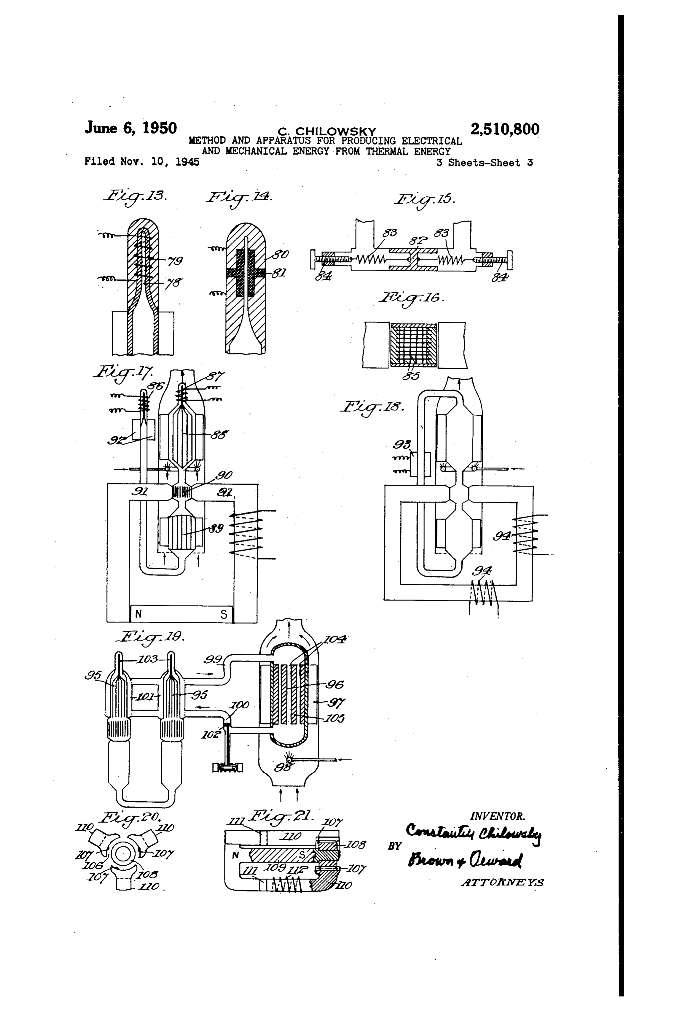
However, only the use of metallic liquids, and Fig. 8 represents a vertical detail section of nost particularly of alkaline metals (sodium modified form of fluid heater; potassium, and their alloys and lithium) repre Fig. 9 represents a vertical detail Section, partly sents a practical industrial solution of the heat in elevation, of a form of fluid column OScillating ing and cooling problem. For instance, the 29 eanS molten sodium, due to its high Specific heat Fig. 10 represents a vertical detail Section of (about 0.3), its relatively great thermal conduc a modified form of fluid column oscillating tivity, its small density (in the Aneighborhood of eaS 1.0), its high boiling point (880° C.) and its Fig. 11 represents a vertical detailed section of chemical passivity in regard to iron and to nickel, a thermally operated oscillating means; permits transferring to, or removing fron, the Fig. 12 represents a vertical detail Section of a aminae of the interrupter section very great modified form of the means shown in Fig. 11: amounts of heat Within a very short time With a Figs. 13 and 14 represent vertical detail Sec minimum of thermal gradient and With a raini tions of other forms of Said means: num of pressure necessary to Aove the iuid. 30 Fig. 15 represents a vertical detail Section of an In certain cases, moiten lead, fusible molten al oscillation frequencer regulator; loys, for instance, lead and bismuth, etc., or the Fig. 16 represents a modification of the detail metallic vapors of Sodium, potassium and ner shown in Fig. 4;
cury, under pressure, can also be used. 3igs. 7 and 18 represent vertical Sections, The interrupter sections consist generally of Sis partly in elevation, of generators having a single thin kaminae of ferromagnetic Substance, (e. g., transverse interrupter Section; soft iron) arranged parallel to each other in the Sig. 19 represents a vertical section of a gen direction of the magnetic lines of force. The erator in which the primary heating and cooling heating and cooling fluids pass between the liquid is heated by circulation of a Secondary laminae, preferably perpendicularly to the mag 40 heating liquid;
netic field. The thickness of the ferromagnetic Fig. 20 represents a detail elevation of the lamina may vary between 0.1 mm. and 1 nm. rotor end of a thermomagnetic motor, and and if necessary, up to the usual thickness of Fig. 21 represents a longitudinal Section on the the sheet iron plates forming the magnetic core line XXI-XXI of Fig. 20.
of the generator. Means are also provided for It will be understood that the drawings are reducing the thickness of the laminae even below largely diagrammatic and do not purport to 0.1 mm. show all conventional structural details. The above described combination of heating In the generator shown in Figs. I and 2, the and cooling by metallic liquids or fluids, with ferromagnetic armature comprises symmetrical lamination of the ferromagnetic interrupter Sec 50 parts , 2, shown as generally U-shaped, and tions, insures the possibility of producing electric having their ends connected by transverse sec currents of industrial (commercial) frequency tions 3, 4 made up of slightly spaced parallel of 50 cycles and even more. thin laminae (preferably of iron) set in magnetic The produced alternating current may be supports 5 and faced on the outside by non utilized to insure and control the operation and 55 magnetic covers 6 (Fig. 2). The sections 3, 4 are automatic synchronization of the distributors, open on two faces for the circulation of heating valves and other parts (or mechanisms) insuring and cooling fluids through the circuits shown in the alternation of circulation of the cold, and Fig. 1. In this figure a heater is shown as a hot, liquids between the laminae. But it is also block of heat-conductive metal traversed ver provided that the desired frequency may be in tically by narrow channels 8 and provided with posed by any mechanical or electric apparatus, fins 9 for picking up heat from the burners O, possessing its own constant frequency of oscil to which gas or the like fuel is Supplied from a lation and that said apparatus will impose its source not shown.
frequency on the said distributors. The fluid circuit system from the sections 3, The invention also provides for the utiliza 65 4 includes the pipes , 2, the distributor 3, the tion of the same methods of lamination of ferro propeller f4 (which may be driven by a hermeti magnetic material and its alternative cooling cally sealed magnetic motor 5 suitably placed at and heating (particularly by means of metallic a point outside the generator), the channels 8, a fluids), to transform heat into mechanical energy second distributor 6 and pipes 7, 8 leading back, of movement and particularly of rotation. O respectively, to the sections 3, 4; this system being Practical embodiments of the invention are adapted to supply fluid, heated in the channels represented in the drawings, in which: 8 to a temperature above the Curie point of the Fig. 1 represents a vertical section through a laminae in sections 3, 4, alternately to Said sec typical form of generator: tions according to the operation of the distribu Fig. 2 represents a horizontal Section, partly s tors 3 and 6. The system just described is
Page 6
enclosed within a thick, heat-insulating casing thermal insulation for the fluid circulating sys having a central vertical passage 2. tems. The several fluid conduits should have A cooler 2, similar in construction to the Smoothly faired inner contours and cross-sec heater 7, is located in the lower part of the pas tions to avoid the formation of eddies. sage 20 within a thin-walled extension 22 of the Fig. 4 represents a horizontal section through casing, the cooler being provided with channels a modified form of interrupter in which the hot 23 and fins 24. The cooling fluid circuit system and cold fluids are kept entirely separate. A from the sections 3, 4 includes the pipes 25, 26, large number of thin-walled iron tubes 38, pref the distributor 27, the propeller 28 (driven by a erably arranged in straight rows, are set in head motor 29), the channels 23, a second distributor 10 ers 38 and enclosed peripherally by non-mag 30, and pipes 3, 32 leading back, respectively, to netic walls 40. At the open ends of the tubes the sections 3, 4; this system being adapted to narrow spaces are left between the headers 3 supply fluid, cooled in the channels 23 to a tem and plates 4, which spaces communicate with perature below the Curie point of the laminae, peripheral channels 42, 43. The plates 4 may alternately to the sections 3 and 4 as determined be in contact with the ends ', 2' of the arma by the distributors. ture parts, providing magnetic continuity through In operation, the propellers 4 and 28 are the walls of the channels 42, 43, the headers 39 driven continuously by their motors, and the dis and the tubes 38. One of the fluids, for instance tributors 3, 6, 27 and 30 are actuated simul the hot fluid, is supplied by the conduit 44 to the taneously to cause fluid from the cooler 2 to 20 channel 42, circulates through the tubes 38, chan flow through one of the sections 3 or 4 while nel 43 and out the conduit 45. The other fluid, fluid from the heater is flowing through the for instance cold, circulates in the chamber other of said sections, the distribution of both formed by the headers 39 and walls 40, to which fluids being alternated between said sections it may be supplied by a conduit 46, being with with the desired frequency. 25 drawn through a similar conduit in the opposite The armature , 2, 3, 4 is shown as being polar wall of the chamber; this fluid thus passes be ized, for instance, by association with a power tween the rows of tubes in contact with the outer ful permanent magnet 33 (Fig. 2) and the several Surfaces thereof. Instead of rows of tubes, it sides of the armature are provided with windings would be possible to substitute double laminae 34. When the magnetic permeability of the sec 47 reinforced by spacers 48, as shown in Fig. 4a. tions 3, 4 is interrupted by heating the laminae in In the arrangement of Fig. 4 both liquids are said sections above the Curie point, the mag constantly in contact with the walls of the tubes, netic flux in the corresponding side of the arma but the liquids are caused to move alternately so ture is modulated and electric current is induced that the walls will quickly take the temperature in the winding thereof; the alternate heating 35 of the moving fluid. This result is facilitated if and cooling of the sections 3 and 4 thus pro the spaces for fluids are made smaller than the ducing alternating current in said windings, with maSS of the tube walls.
a frequency corresponding to the frequency of Figs. 5, 6 and 7 show a form of generator in the temperature changes. This frequency may be which the heating and cooling are effected by the constant or may be changed almost instantly 40 oscillation of a single column of metallic liquid when desired. having heated and cooled parts. The armature, The arrangement of the heater 7, cooler 2 and windings and permanent magnet of Fig. 7 cor passage 20 is such that cooling air is drawn past respond to those shown in Fig. 2 and transverse the fins 20 where it picks up a certain amount Sections 49, 50 of laminae are provided as before. of heat before passing on to the burners O which 45 The liquid heating and cooling system includes add sufficient heat to maintain the heater (and a heater 5 and cooler 52 for liquid traversing the fluid in the channels 8 thereof) at a temperature Section 49, and a heater 53 and cooler 54 for liquid above the Curie point of the laminae; the heated traversing the section 50, each heater and cooler air passing the fins 9 and on out the top of the being similar to those described above and shown passage 20. 50 in Fig. 1. The liquid circuit is continuous, the The fluid circulation system shown in Figs. 1 upper ends of the heaters being connected by a and 2 is subject to considerable variation, for ex conduit 55 and the lower ends of the coolers be ample, as indicated in Fig. 3 where two heaters ing connected by a conduit 56. Means for oscil 7, 7' and two coolers 2', 2' are connected to lating the liquid column is indicated diagram a single central 8-way distributor 35, the fluid SS matically at 57 and it will be noted that this is in being moved through the several closed circuits the cool part of the apparatus with obvious ad by propellers 36 driven by motors 37. vantages resulting from such location. When It is evident that, by using three-branched the liquid column is oscillated by the means 57, armatures instead of two-branched as shown, hot liquid is drawn down from one heater to its with a transverse laminated interrupter section 80 corresponding laminar section 49 or 50 while cool and hot-and-cold fluid supply systems in each ing liquid is simultaneously passed up from the branch, it is possible to obtain a three-phase opposite cooler to the other section, and vice alternating current. Other multiphase currents versa with a frequency of heating and cooling may be obtained, in the same manner, as will be corresponding to the frequency of oscillation, the readily understood. hot liquids being maintained always above the If necessary a thin layer of thermal insulation Curie point of the laminae and the cooling liquids may be inserted between the supports 5 and the being below that point, with sufficient margins ends of the armature parts to reduce heat losses to ensure efficient operation. from the laminae. The surfaces of the laminae The laminations (or tubes, as in Fig. 4) and the may also be covered by very thin layers of elec 70 Spaces between them should in all cases be so tric insulation to reduce Foucault currents. The dimensioned that the volume of liquid needed for relative positions of the heater, cooler and inter heating or cooling during a half cycle is sub rupter Sections may be varied, as by spacing the stantially greater than the volume of said spaces, heater and cooler a convenient distance from in order to obtain uniformity of temperature the armature assembly and providing adequate 7 throughout the laminations.
Page 7
Fig. 8 represents a modified form of heater shown in Figs. 13 and 14. In Fig. 13 the small comprising a large chamber 58 having external tube 78 is shown as being surrounded by an elec fins 59 which may be heated by products of Com tric resistance coil 79. In Fig. 14 the upper end bustion from a burner (as in Figs. 1 and 5) and 80 of the head is insulated from the lower part of internal fins 60 which transmit the heat to the the head by a body of refractory insulating ma liquid. Efficient circulation of the liquid in the terial 8, and vaporization of the liquid metal in chamber can be ensured by shaping its connec the tube is effected by electrical discharge tions to upper and lower conduits as shown, the through said metal. between the parts of the lower connection being angular while the upper head.
connection is smoothly conical; oscillation of the Fig. 15 shows a form of frequency regulator fluid through the chamber will cause eddies (in which may be introduced into the lower part of dicated by the arrows) and result in thorough the liquid column. A sliding piston 82 is mount heating of the fluid. Such heaters may be used, ed in the liquid conduit and attached to springs for instance, in place of the heaters 5 and 53 83, the tension and natural frequency of which of Fig. 5. 5 may be regulated as by the screws 84. It will be Details of a liquid column oscillator (57 in Fig. understood that an electromagnetic oscillator of 5) are shown in Fig. 9. A piston Or plunger the type shown in Fig. 9 could also be used with 6 of magnetic material is fitted freely in the con the arrangement shown in Figs. 11 and 12. duit 56 between springs 62, the outer ends of The laminae in the transverse interrupter sec which may be retained by rings 63. The bifur 20 tions may be reinforced in various ways as by the cated armature 64 of an electro-magnet, polarized provision of a middle layer of tungsten or tan by the application of the poles of a permanent talum, for instance, (having high strength even magnet, is provided with windings 65 through at elevated temperatures) between adherent sur which alternating current may be passed, the face layers of iron; or by the provision of rein piston 6 being thus oscillated with the frequency 26 forcing Spacers 85 connecting the laminae and of reversal of the current. The natural frequen extending in the direction of flow of the heating cy of the spring-piston-liquid column assembly and cooling fluids, as shown in Fig. 16. should be considered in order to obtain the best In the apparatus described above it is prefer results. able to use metallic liquids as the heating and Another form of oscillator is shown in Fig. 10 cooling fluids, because of the high specific heat where a piston 66 is arranged to be reciprocated 30 and conductivity of such liquids. It will be un by the eccentric 67 on the shaft of a motor 68. derstood, however, that Super-heated metallic va Fig. 11 shows an arrangement in which the pors under pressure (mercury, for instance) can liquid column is Oscillated by thermal energy re be used in some cases, with appropriate changes sulting from rapidly alternating formation and in the dimensions of the system. It would also condensation of metallic vapor at two closed up be possible to use such rare gases as helium, neon, per ends of the column. In this case, the liquid argon and the like, which gases are chemically channels 69, 70 in a pair of heaters (such as heat inert with respect to the laminae. ers 5, 53 of Fig. 5) terminate above the heaters In the above described cases of utilization of a in tubes 7, 72 of relatively small cross-section 0. permanent magnet, advantage was taken of the with their upper ends sealed. These tubes are possibility of obtaining powerful magnetic fluxes formed in heat-conductive heads 73, 74 provided and high magnetic fields.
with fins 75 which project into the stream of But it is also possible to use, instead of a per heated gas flowing up from the fins of the heat manent magnet, a core of soft iron with windings, ers. When the ratio of the heat-exchanging Sur 45 suitably traversed by the currents, conveniently faces of the fins 75 and heads 73, 74 to the volume rectified, produced by thermal interruption of the of liquid metal in the tubes 7, 72 is sufficiently magnetic flux. It is also provided to use two sep large (and greater than the corresponding ratio arate armatures, dephased by 180°, the currents in the heaters) the liquid in the tubes 7, 72 will of one of the armatures, suitably dephased, acting be vaporized. If necessary, however, the super 50 on the magnetic flux of the other, and vice versa. heating of the heads 73, 74 may be assured by It is also possible to obtain three phase currents the provision of an additional burner 76, with its by using armatures with three branches and own air Supply through the pipe 77, as shown in three dephased interruptions with 120° electrical Fig. 12. angle therebetween, or three separate armatures. In the apparatus shown in Figs. 11 and 12, it is Other multi-phase currents could be obtained in assumed that the liquid metal column does not a similar manner, as will readily be understood. completely fill the closed system in which it is For starting, the residual magnetism or a flux contained, and that said system is evacuated. produced by an auxiliary starting current may be When oscillation has been initiated in any suit used.
able manner by forcing the liquid at One end of It is also possible, as shown in Figs. 17 and 18, the column to rise into the tubes 7 or 72, the 50 to use generators with a single interrupter section liquid in Said tubes will immediately be vaporized in a single armature, with or without a perma and the vapor pressure will forcefully move the nent magnet. In Fig. 17 there is an oscillating column through the heaters and coolers until its metallic liquid column maintained in oscillation other end penetrates into the other super-heating by superheaters 86, 87 such as that shown in Fig. tubes, when the operation will be repeated in the 65 13, one branch of the column being arranged to opposite direction. The metallic vapor will be pass through a heater 88, cooler 89 and laminar Condensed when it passes out of the tubes and so interrupter Section 90 of the armature 9. Fins will be in condition to be vaporized again on the 92 are provided for cooling and condensing the following cycle. Oscillation of the column with 70 metallic vapors formed in the superheater 86. any desired frequency, depending on the speed Fig. 18 shows a similar arrangement (for in of vaporization, can thus be maintained automat stance, without a permanent magnet) in which the column of metallic liquid (in a closed circuit) ically parts.
without the use of any moving mechanical - -isoscillated by an oscillator 93 similar to the one Modified forms of Super-heating tubes are 5 shown in Figs. 9 or 10. Windings 94 are provid ed for the dephased current,
Page 8
In the forms of generators hereinabove de ally dephased by 120", for forming a magnetic scribed the fluid heaters, whether with continu rotary field, capable of entraining rotors, and also ous circulation or with oscillation of the metallic to construct electric motors, of a polyphase "ther liquid column, were directly heated by the flame momagnetic' type, particularly three phase. or products of combustion, with the inconvenient 5 For this purpose, in an armature of the de encumbrance of the several conduits in proximity scribed type with several branches, and having in to the heated laminations and the armature. The each branch an interrupter section for modulat electric control of the temperature by regulat ing the magnetic flux with a definite frequency, ing the fuel also presents difficulties due to the a cut or space is made in each branch to provide inertila. 0. room for placing in these spaces or recesses, and In an important modification shown schemati notably in the magnetic variable field thereof, the cally in Fig. 19, the heaters for the liquid in cir movable elements of the rotor. These cuts or culation or in oscillation across the laminations, Spaces, forming the rotor magnetic field, will be are heated not directly by the products of com also, in each branch, in series with the interrupter bustion but by circulation of a secondary metallic sections, liquid in a separate circuit which includes chan The channels of heating should be located at nels in the heater or heaters, and channels in points in the armature branches sufficiently dis another separate reheater, called a secondary re tant from the rotor, and this is very important, heater. It is heated directly by the flame or by in order that the rotor and the plates of the mag the products of combus' ion and can be larger, 20 netic flux in which it roates, can be maintained with a greater heating surface of a higher thermal at a sufficiently low temperature for an element output, but it does not encumber the generator of rotation.
itself, being connected with the primary heater The rotor. should be constructed according to or heaters by tubes with suitable thermal insula the particular type of the motor-synchronous, tion. 25 aSynchronous, or other type-which may be de Because of the rapidity of the transmission of sired and Suitable for operation in a variable heat in the primary heater from the secondary magnetic field.
liquid to the primary liquid, through a wall which Figs. 20 and 21 show a schematic end elevation can be made relative'y thin, the automatic tem and a corresponding longitudinal section, of a perature control of the primary liquid can be 30 three-phase thermomagnetic motor with rotating more accurate and more rapid. Actually, the field.
control element can act, in the first place and In Fig. 20, 06 is a circular section of a rotary with a rapid result, on the velocity of circulation magnetic field. foll, OT, OT are plates constitut of the secondary liquid; the temperature of the inng three poles of the rotating field. In this case secondary liquid being capable to be controlled, : 5 of the utilization of a permanent magnet, central with a less rapid phase, by the action of the com or axial (polarized motor), these three plates rep bustion. resent the same polarity (for instance, north) but The same arrangement can be applied, if de of variable intensity. O8 is a piece of soft iron sired, also to the "cold' liquid. The cooling of with the opposite polarity (for instance, south). the cold circuit can, however, be largely assured In Fig. 21, 109 is an axial permanent magnet. by simple thermic radiation. . w fo is one of the three branches of the magnetic In Figs. 19, 95, 95 are primary heaters for the armature. If, if f are thermal interrupters of OScillating liquid column, and 96 is a secondary the magnetic flux, with heated iron laminations, reheater with fins 97, heated by the products of alternately cooled, with dephasing of 120°. (Ar combustion of a burner 98. Tubes 99, Oe are s rangements for heating are not shown, having provided for the closed circulation of the sec already been described in detail). 2 is a wind ondary liquid between the secondary reheater ing whose electric current can be used in the and the two primary heaters 95 which have chan nels or jackets of for passage of the secondary rotor.
of the
The rotor, entrained by the rotary field gap 06, is not shown on the drawing. It fluid. A propeller 02 assures the circulation of 50 can be arranged according to the type of the the secondary liquid and devices for assuring the motor.
oscillation of the primary circuit are indicated If desired, the part 08 can be movable and at 03. The secondary liquid is heated in the can, by itself, constitute a rotor. If desired, in tubes O4 in the block O5. stead of the permanent magnet 09, the magnetic If desired, this secondary circulation can be flux can be produced by the current in the wind maintained by thermal syphoning. In such a ings 2, acting on the different branches with case, the direction of the circulation could be re suitable dephasing.
versed and the metal in the tubes foll of the sec The OScillation of the three columns of the ondary reheater, circulating from the bottom to liquid metal, heating and cooling the laminations the top. could be heated to a more or less pro nounced boiling. of the three sections fl. can be assured, for in The circulation of the metallic liquid in the stance, by three pistons with dephased action and magnetic winding, placed in the space under the secondary circuit can also take place, if desired, junction of the three columns. This entrainment in the form of an oscillation, generally slower can be also effected by three dephased oscillators, and with the volume of the displacement of the 5 with gas or vapor, described above, placed on the liquid being more or less equal to, or greater than, lipper ends of the three columns, these columns the total volumes of the two conduits and of the having their cool lower ends joined in a common capacity of the primary heater or heaters. junction.
As was indicated above, the generator can be In the case of use of armatures polarized by made for a multiphase current, for instance, as a 70 application of a permanent magnet (for instance, three-phase generator, using an armature with Figs. 2 and 7) with bifurcation of the magnetic three branches, with three branches of the flux flux between different branches of the armature, interruption, dephased by 120° between interrip the interruption of the magnetic flux in the tions. But it is also provided to use such a sys branches dephased by 180°, will induce in the ten, for instance, with three interruptions, mutu respective windings two alternating induction
Page 9
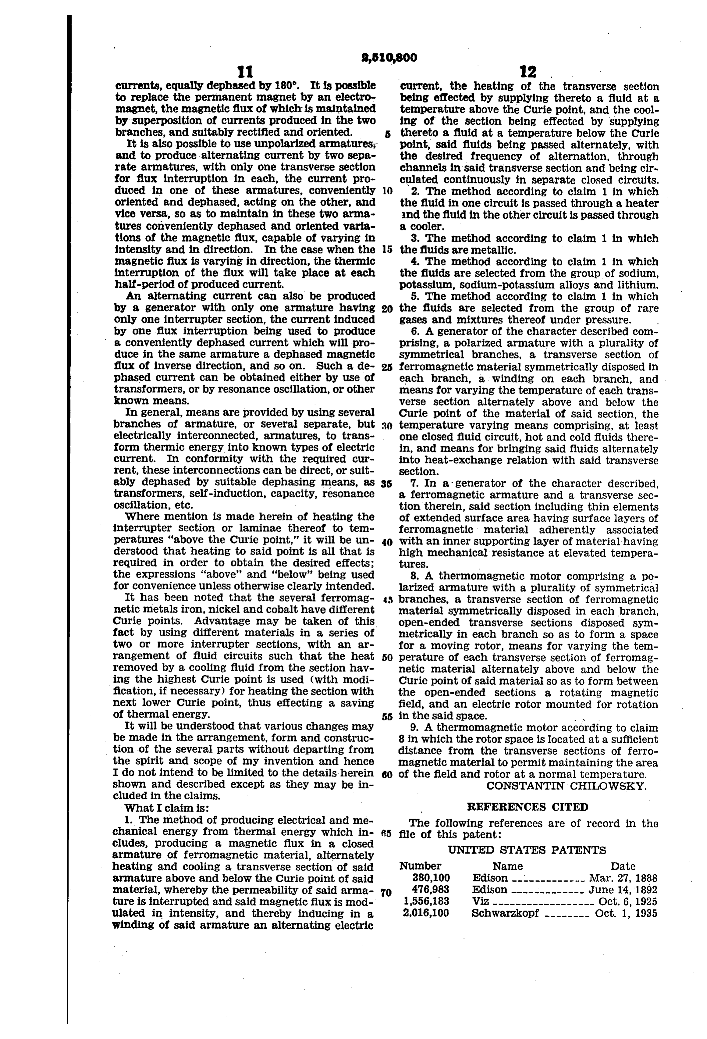
currents, equally dephased by 180. It is possible current, the heating of the transverse section to replace the permanent magnet by an electro being effected by supplying thereto a fluid at a magnet, the magnetic flux of which is maintained temperature above the Curie point, and the cool by superposition of currents produced in the two ing of the section being effected by supplying branches, and suitably rectified and oriented. thereto a fluid at a temperature below the Curie It is also possible to use unpolarized armatures; point, said fluids being passed alternately, with and to produce alternating current by two sepa the desired frequency of alternation, through rate armatures, with only one transverse section channels in said transverse section and being cir for fux interruption in each, the current pro culated continuously in separate closed circuits. duced in one of these armatures, conveniently 10 2. The method according to claim 1 in which oriented and dephased, acting on the other, and the fluid in one circuit is passed through a heater vice versa, so as to maintain in these two arma and the fluid in the other circuit is passed through tures conveniently dephased and Oriented varia a cooler.
tions of the magnetic flux, capable of varying in 3. The method according to claim 1 in which intensity and in direction. In the case when the 5 the fluids are metallic.
magnetic flux is varying in direction, the thermic 4. The method according to claim 1 in which interruption of the flux will take place at each the fluids are selected from the group of SOdium, half-period of produced current. potassium, sodium-potassium alloys and lithium, An alternating current can also be produced 5. The method according to claim 1 in which by a generator with only one armature having 20 the fluids are selected from the group of rare only one interrupter section, the current induced gases and mixtures thereof under pressure. by one flux interruption being used to produce 6. A generator of the character described com a conveniently dephased current which will pro prising, a polarized armature with a plurality of duce in the same armature a dephased magnetic symmetrical branches, a transverse section of flux of inverse direction, and so on. Such a de 25 ferromagnetic material symmetrically disposed in phased current can be obtained either by use of each branch, a winding on each branch, and transformers, or by resonance oscillation, or other means for varying the temperature of each trans known means. verse section alternately above and below the In general, means are provided by using several Curie point of the material of said section, the branches of armature, or several separate, but 3. temperature varying means comprising, at least electrically interconnected, armatures, to trans One closed fluid circuit, hot and cold fluids there form thermic energy into known types of electric in, and means for bringing said fluids alternately current. In conformity with the required cur into heat-exchange relation with said transverse rent, these interconnections can be direct, or suit Section.
ably dephased by suitable dephasing means, as 7. In a generator of the character described, transformers, self-induction, capacity, resonance a ferromagnetic armature and a transverse sec oscillation, etc. tion therein, said section including thin elements Where mention is made herein of heating the of extended surface area, having surface layers of interrupter Section or laminae thereof to tem ferromagnetic material adherently associated peratures "above the Curie point,' it will be un 40 with an inner supporting layer of material having derstood that heating to said point is all that is high mechanical resistance at elevated tempera required in order to obtain the desired effects; tures.
the expressions 'above' and 'below' being used 8. A thermomagnetic motor comprising a po for convenience unless otherwise clearly intended. larized armature with a plurality of Symmetrical It has been noted that the Several ferronag branches, a transverse section of ferromagnetic netic metals iron, nickel and cobalt have different material symmetrically disposed in each branch, Curie points. Advantage may be taken of this open-ended transverse sections disposed sym fact by using different materials in a Series of metrically in each branch so as to form a Space two or more interrupter sections, with an ar for a moving rotor, means for varying the tem rangement of fluid circuits such that the heat 50 perature of each transverse Section of ferronag removed by a cooling fluid from the section hav netic material alternately above and below the ing the highest Curie point is used (with modi Curie point of said materialso as to form between fication, if necessary) for heating the section with the open-ended Sections a rotating magnetic next lower Curie point, thus effecting a Saving field, and an electric rotor mounted for rotation of thermal energy. 55 in the said space. --- - It will be understood that various changes may 9. A thermomagnetic motor according to claim be made in the arrangement, form and construc 8 in which the rotor Space is located at a Sufficient tion of the several parts without departing from distance from the transverse sections of ferro the Spirit and Scope of my invention and hence magnetic material to permit maintaining the area I do not intend to be limited to the details herein 60 of the field and rotor at a normal temperature. shown and described except as they may be in CONSTANTIN CHILOWSKY. cluded in the claims.
What I claim is: REFERENCES CITED 1. The method of producing electrical and me The following references are of record in the chanical energy from thermal energy which in file of this patent:
cludes, producing a magnetic flux in a closed UNITED STATES PATENTS armature of ferromagnetic material, alternately heating and cooling a transverse section of said Number Name Date armature above and below the Curie point of said 380,100 Edison ------------- Mar. 27, 1888 material, whereby the permeability of said arma 70 476,983 Edison ------------- June 14, 1892 ture is interrupted and said magnetic flux is mod 1556,183 Viz ------------------ Oct. 6, 1925 ulated in intensity, and thereby inducing in a 2,016,100 Schwarzkopf -------- Oct. 1, 1935 winding of said armature an alternating electric
Provenance
- Collection
- Cited prior art
- Original PDF
- patentimages.storage.googleapis.com →
- Filed
- 1945-11-10
- Pages
- 9
- Method
- pdftotext (the PDF's own text layer) + pdftoppm 300dpi page scans
- Source
- Google Patents bibliographic record
- Granted
- 1950-06-06
- Inventors
- Chilowsky Constantin
- Transcribed from
- patentimages.storage.googleapis.com →