patent · US4172019
Method and apparatus for preventing agglomeration within fluid hydrocarbons
23 October 1979
Page 1 — bibliographic record
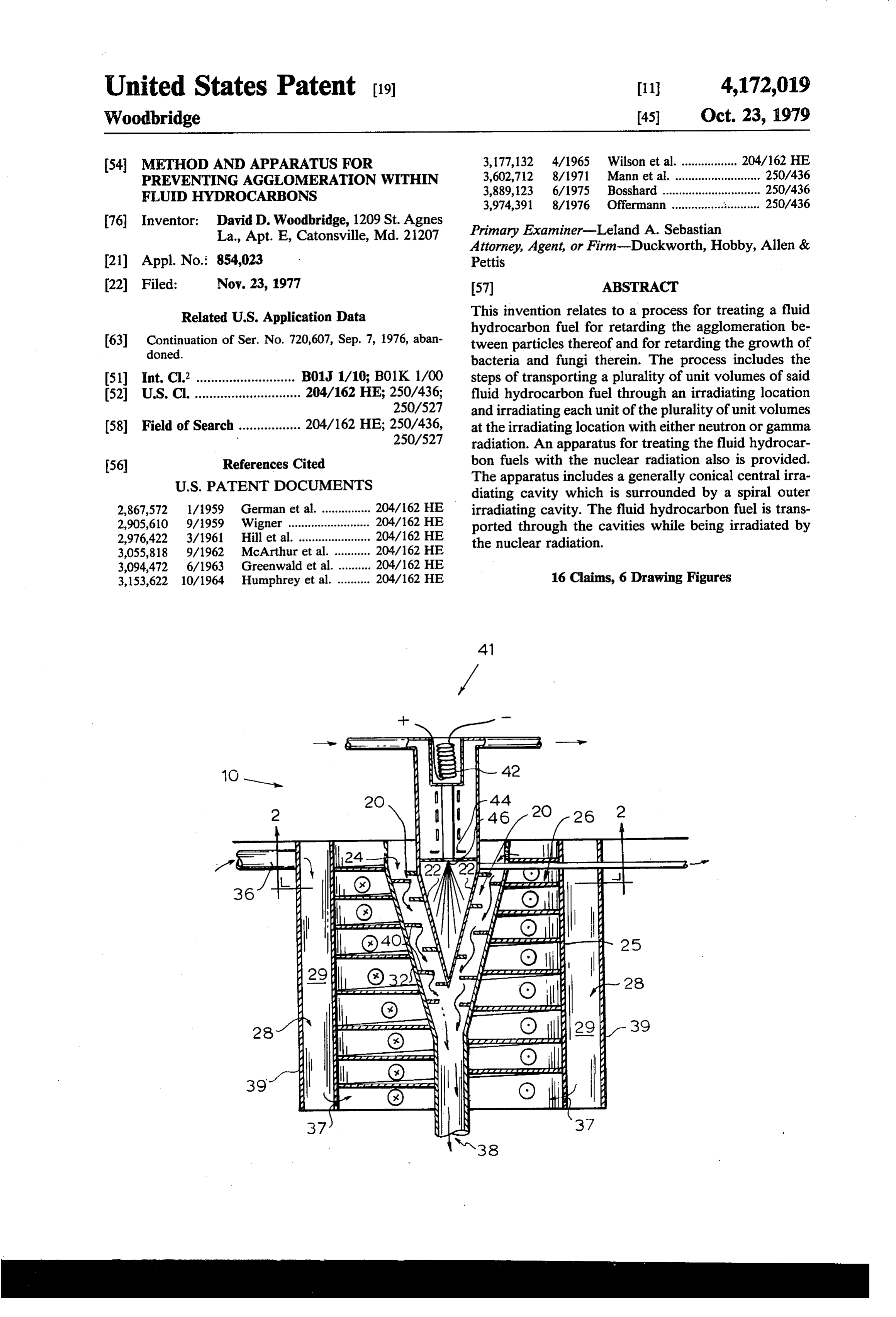
United States Patent (19) 11 4,172,019 Woodbridge 45) Oct. 23, 1979 (54) METHOD AND APPARATUS FOR 3,177,132 4/1965 Wilson et al. ................. 204/162 HE PREVENTING AGGLOMERATION WITHN 3,602,712 8/1971 Mann et al. .......................... 250/436 FLUID HYDROCARBONS 3,889,123 6/1975 Bosshard ... ... 250/436 3,974,391 8/1976 Ofermann .... ... 250/436 76 Inventor: David D. Woodbridge, 1209 St. Agnes Primary Examiner-Leland A. Sebastian La., Apt. E, Catonsville, Md. 21207 Attorney, Agent, or Firm-Duckworth, Hobby, Allen & (21) Appl. No.: 854,023 Pettis (22) Filed: Nov. 23, 1977 57 ABSTRACT Related U.S. Application Data This invention relates to a process for treating a fluid hydrocarbon fuel for retarding the agglomeration be 63 Continuation of Ser. No. 720,607, Sep. 7, 1976, aban tween particles thereof and for retarding the growth of doned.
bacteria and fungi therein. The process includes the (51) Int. C.’........................... B01J 1/10; B01K 1/00 steps of transporting a plurality of unit volumes of said (52) U.S. C. ............................. 204/162 HE; 250/436; fluid hydrocarbon fuel through an irradiating location 250/527 and irradiating each unit of the plurality of unit volumes (58) Field of Search ................. 204/162 HE; 250/436, at the irradiating location with either neutron or gamma 250/527 radiation. An apparatus for treating the fluid hydrocar 56 References Cited bon fuels with the nuclear radiation also is provided.
diating cavity which is surrounded by a spiral outer 2,867,572 1/1959 German et al. ............... 204/162 HE irradiating cavity. The fluid hydrocarbon fuel is trans 2,905,610 9/1959 Wigner ............. ... 204/162 HE ported through the cavities while being irradiated by 2,976,422 3/1961 Hill et al. .............. ... 204/162 HE the nuclear radiation.
3,055,818 9/1962 McArthur et al. ........... 204/162 HE 3,094,472 6/1963 Greenwald et al. .......... 204/162 HE 3,153,622 10/1964 Humphrey et al. .......... 204/162 HE 16 Claims, 6 Drawing Figures
Faaaaaaaaaaaaaad
Yan
Page 2
Drawing sheet — no readable text.
Page 3
Drawing sheet — no readable text.
Page 4
addition to the normal heating which occurs, as de
METHOD AND APPARATUS FOR PREVENTING scribed in the previous application, the lubricating oil AGGLOMERATION WITHIN FLUID and olefin additives absorb high energy neutrons which HYDROCARBONS act as a catalyst in the chemical grafting or combination 5 of the olefin chain onto the molecular structure of the
This is a continuation of application Ser. No. 720,607 lubricating oil. This chemical reaction improves the filed Sept. 9, 1976 now abandoned. viscosity index of the lubricating oil. Another similar BACKGROUND OF THE INVENTION chemical reaction catalyzed by the presence of nuclear particles is disclosed by Ogorzaly, in U.S. Pat. No.
1. Field of the Invention 10 3,085,057, which describes the conversion of cetane to The present application relates to a process and appa obtain a polymerized product having a high viscosity ratus for treating fluid hydrocarbon fuels with neutron index.
or gamma radiation for retarding agglomeration be Kline, in U.S. Pat. No. 3,137,633, discloses a method tween the particles thereof, for retarding the growth of for polymerizing or depolymerizing organic com bacteria and fungi therein, and for increasing the normal 15 pounds of various molecular weights by exposing the combustion efficiency of the fuel after prolonged peri organic substances to large concentrations of high en ods of storage, and thereby reducing the hydrocarbon ergy gamma rays. This process of gamma irradiation of pollutants produced during the combustion process. the polymers can in some instances promote cross link 2. Description of the Prior Art
Nuclear radiation has been utilized in the prior art for 20 ing the between the molecular chains and inhibit crazing of molecular chains, while in other cases the molecules shortening molecular chains of organic molecules, forming the complex polymer are caused to disengage. lengthening molecular chains of organic molecules, The use of cross linking molecular chains of organic molecules and petroleum high energy gamma rays in the conversion of for promoting or retarding chemical reactions between closed by Wigner intoU.S.
naphtha a higher octane product is dis
molecular chains of organic molecules. 25 Other uses of nuclear radiation for effecting the prob In contrast, the present application relates to the use ability of chemical reactions are disclosed by Hamling, of nuclear radiation, and in particular to the use of neu trons and/or gamma rays to irradiate fluid hydrocar in U.S. Pat. No. 3,378,451, Bolt et al, in U.S. Pat. No. bons, and especially fluid hydrocarbon fuels, for retard 3,238,113, Bolt et al in U.S. Pat. No. 3,123,534, Voor ing the agglomeration process which naturally occurs 30 hees in U.S. Pat. No. 2,958,637; Schutze et al in U.S. Pat. No. 2,914,452; Schlicht et al in U.S. Pat. No.
between the particles of the fluid hydrocarbon during 3,283,814; and Hentz in U.S. Pat. No. 3,258,404. Other storage and subsequent heating. Agglomeration may be generally defined as the process by which a mass of 3,109,781; Denison ininclude prior art references Natland in U.S. Pat. No.
precipitation grows by assimilating other precipitation particles which in the course of normal thermal activity 35 sohoff in U.S. Pat. No. 3,269,915. collide with the precipitation mass and therefore be SUMMARY OF THE INVENTION come part thereof. The probability of two like hydro carbon molecules agglomerating or coalescing may be This invention relates to a process for treating fluid reduced by irradiating the molecules with nuclear radi hydrocarbon fuel for retarding the agglomeration be ation. Experimentation has shown that gamma radiation 40 tween the molecules thereof and for retarding the will perform satisfactorily in reducing the probability of growth of bacteria and fungi therein. The process in agglomeration, but neutron radiation, at least within a cludes the steps of: (a) transporting a plurality of unit suitable range of intensities, appears to be the most volumes of the fluid hydrocarbon fuel through an irra efficient method of reducing agglomeration between diating location; and (b) irradiating each unit volume of the hydrocarbon molecules. While this invention is 45 the hydrocarbon fuel at the irradiating location with described with relation to liquid hydrocarbon fuels such either neutron radiation or gamma radiation. as kerosene, jet fuel, RP-1 rocket fuel, diesel fuel and An apparatus for treating the fluid hydrocarbon fuels gasoline, the general process and apparatus disclosed according to the above-described process includes an herein may be used with similar success upon other irradiating cavity defined by a first inner surface and a hydrocarbons. 50 second outer surface placed generally colsterally there The prior art includes several examples of the use of from. The irradiating cavity includes inlet means and nuclear energy for treating and changing the physical outlet means coupled thereto for enabling a flow of the characteristics of hydrocarbons. For example, Natland, fluid hydrocarbon fuel through the irradiating cavity. A in U.S. Pat. No. 3,297,537, discloses a method and appa source of neutron and/or gamma radiation irradiates ratus for treating crude oil for facilitating the long dis 55 each unit volume of the fluid hydrocarbon fuel within tance transportation through pipelines. Natland trans the irradiating cavity. Shield means are included for ports the thick and viscous crude petroleum oil through absorbing and attenuating nuclear radiation passing the moderator sections of a nuclear reactor, thereby through the irradiating cavity without being absorbed allowing the crude oil to absorb heat generated by the by the fluid hydrocarbon fuel.
nuclear reaction. This heat is normally transferred to THE DRAWINGS the crude petroleum oil by thermal neutrons (as com pared with fast neutrons). The additional heat added to Other objects, features and advantages of this inven the crude petroleum oil decreases the viscosity of the oil tion will be apparent from a study of the written de and thereby reduces the energy required to pipe the scription and the drawings in which:
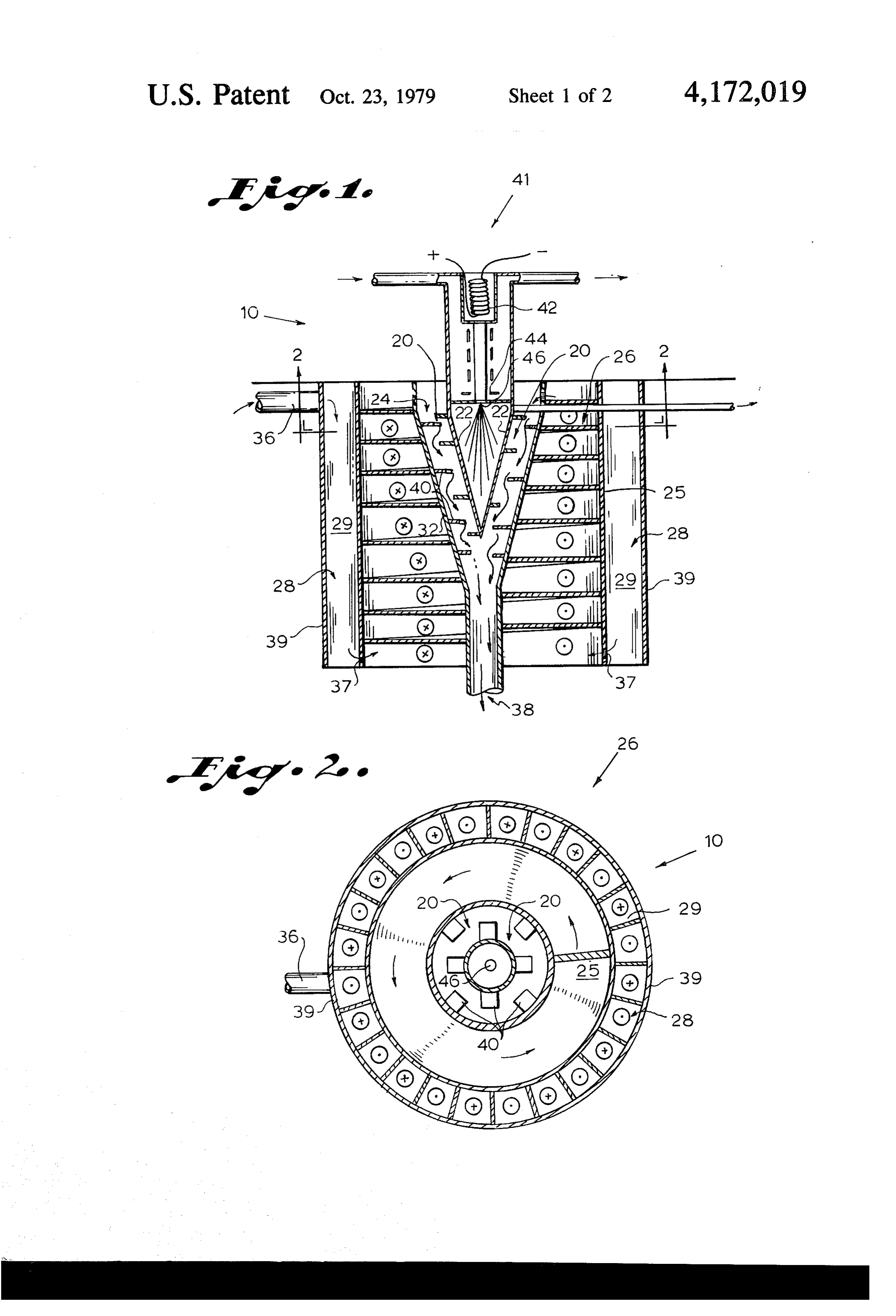
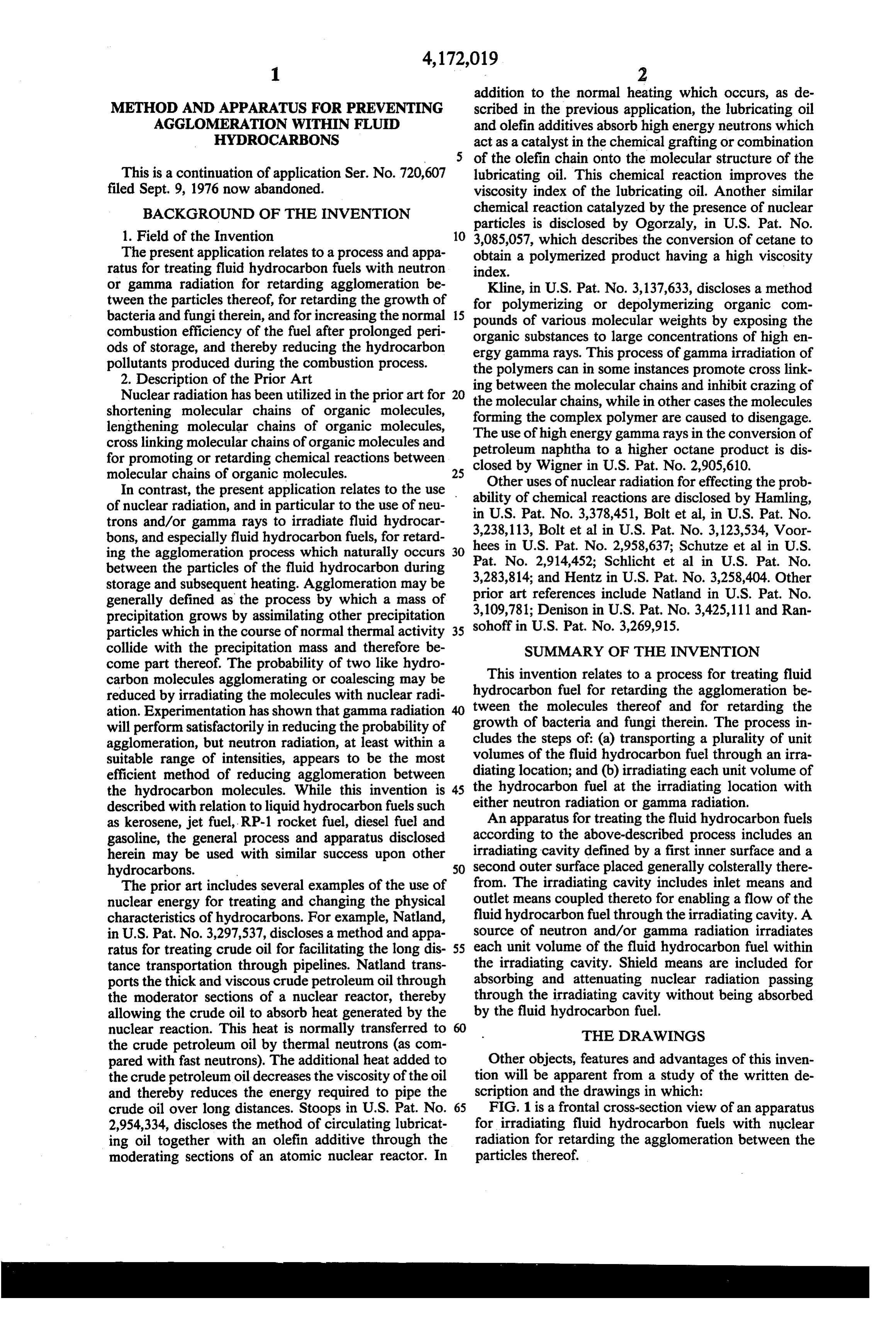
crude oil over long distances. Stoops in U.S. Pat. No. 65 FIG. 1 is a frontal cross-section view of an apparatus 2,954,334, discloses the method of circulating lubricat for irradiating fluid hydrocarbon fuels with nuclear ing oil together with an olefin additive through the radiation for retarding the agglomeration between the moderating sections of an atomic nuclear reactor. In particles thereof.
Page 5
FIG. 2 is a partial top cross-section view of the first period without concern for bacterial and fungicidal preferred embodiment of the present apparatus taken contamination of the fuel.
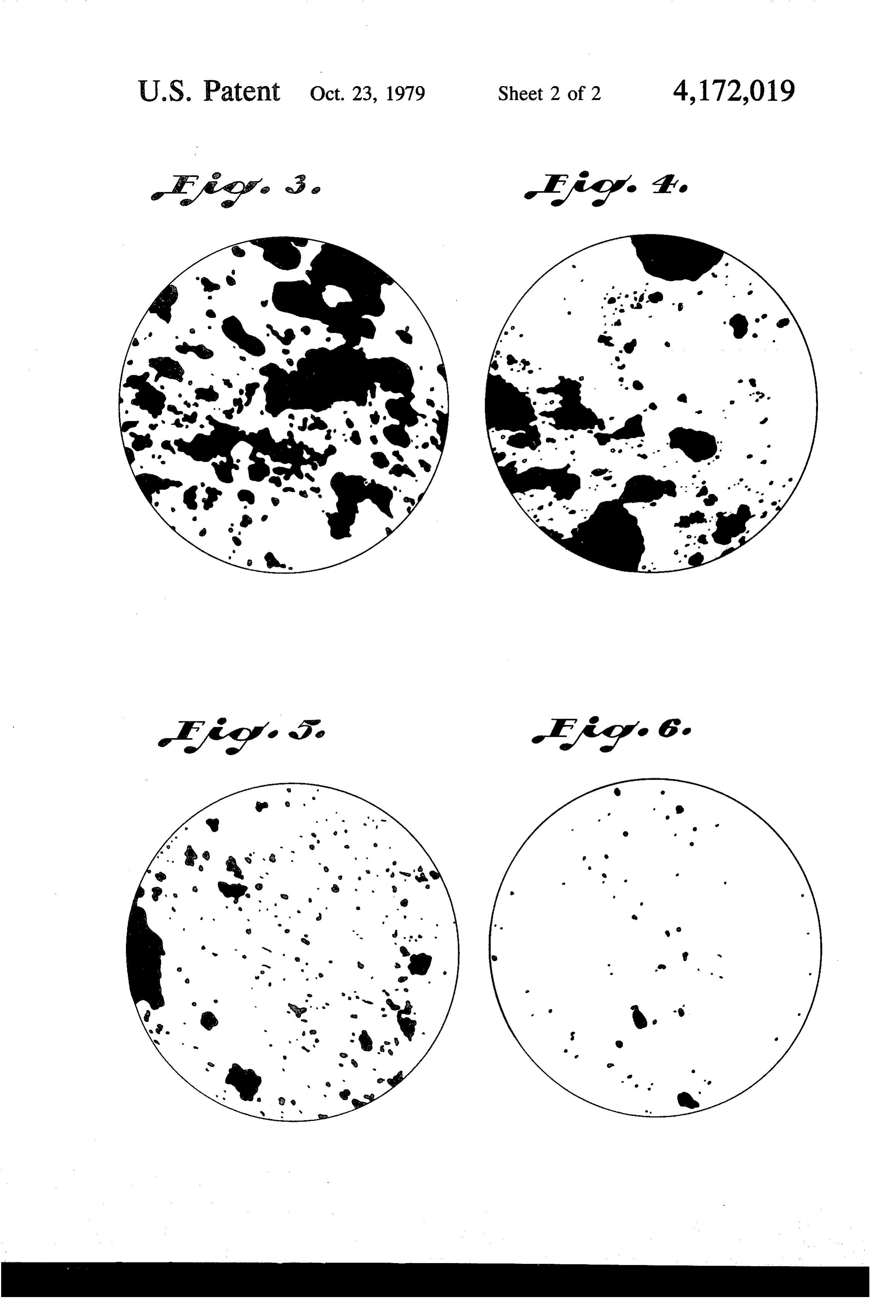
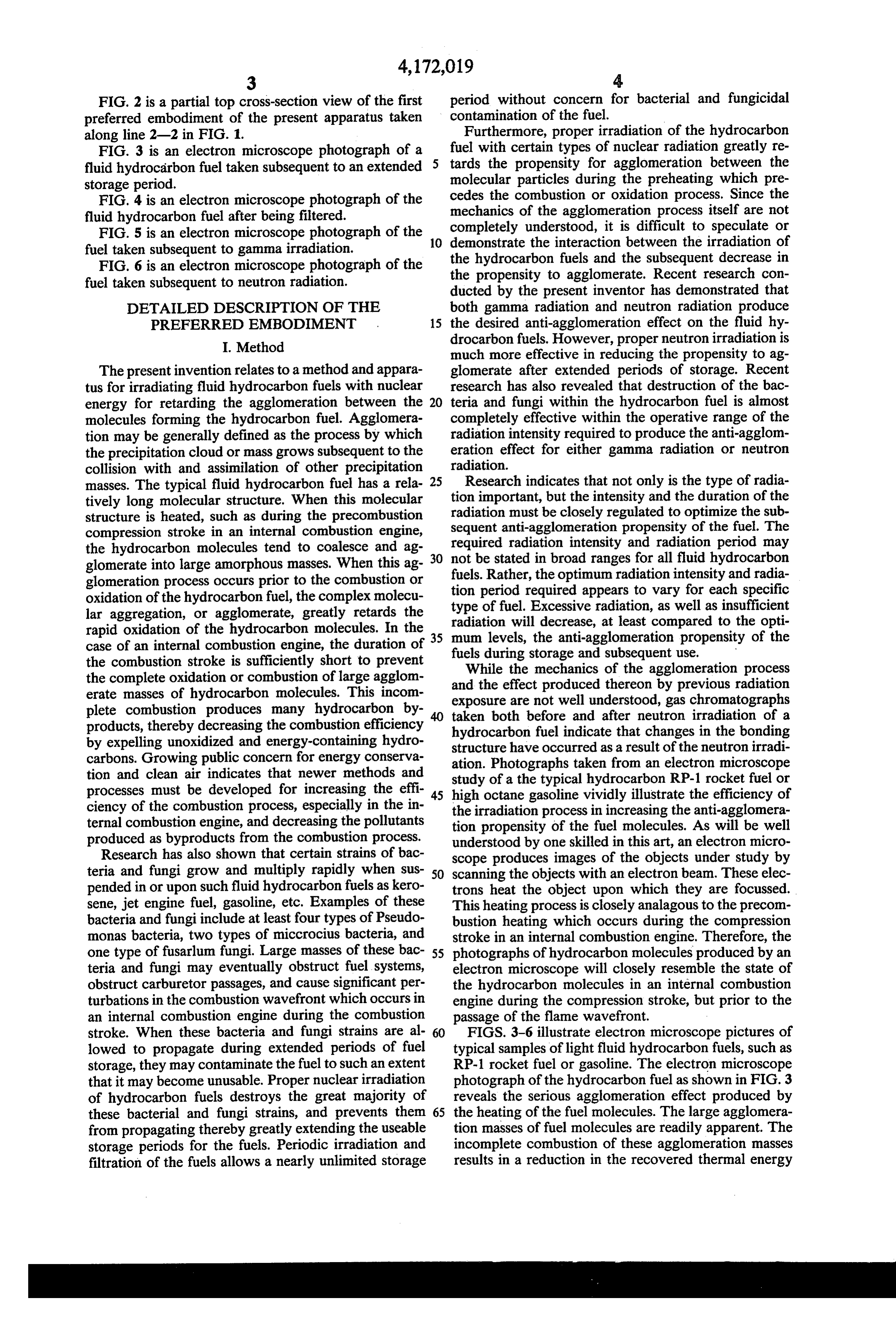
along line 2-2 in FIG. 1. Furthermore, proper irradiation of the hydrocarbon FIG. 3 is an electron microscope photograph of a fuel with certain types of nuclear radiation greatly re fluid hydrocarbon fuel taken subsequent to an extended tards the propensity for agglomeration between the molecular particles during the preheating which pre storage period.
FIG. 4 is an electron microscope photograph of the cedes the combustion or oxidation process. Since the fluid hydrocarbon fuel after being filtered. mechanics of the agglomeration process itself are not FIG. 5 is an electron microscope photograph of the 10 demonstrateunderstood, completely it is difficult to speculate or the interaction between the irradiation of fuel taken subsequent to gamma irradiation.
FIG. 6 is an electron microscope photograph of the the hydrocarbon fuels and the subsequent decrease in the propensity to agglomerate. Recent research con fuel taken subsequent to neutron radiation. ducted by the present inventor has demonstrated that DETAILED DESCRIPTION OF THE both gamma radiation and neutron radiation produce PREFERRED EMBODIMENT 15 the desired anti-agglomeration effect on the fluid hy I. Method drocarbon fuels. However, proper neutron irradiation is much more effective in reducing the propensity to ag
The present invention relates to a method and appara glomerate after extended periods of storage. Recent tus for irradiating fluid hydrocarbon fuels with nuclear research has also revealed that destruction of the bac energy for retarding the agglomeration between the 20 teria and fungi within the hydrocarbon fuel is almost molecules forming the hydrocarbon fuel. Agglomera completely effective within the operative range of the tion may be generally defined as the process by which radiation intensity required to produce the anti-agglom the precipitation cloud or mass grows subsequent to the eration effect for either gamma radiation or neutron collision with and assimilation of other precipitation radiation.
masses. The typical fluid hydrocarbon fuel has a rela 25 Research indicates that not only is the type of radia tively long molecular structure. When this molecular tion important, but the intensity and the duration of the structure is heated, such as during the precombustion radiation must be closely regulated to optimize the sub compression stroke in an internal combustion engine, sequent required anti-agglomeration propensity of the fuel. The radiation intensity and radiation period may the hydrocarbon molecules tend to coalesce and ag glomerate into large amorphous masses. When this ag 30 not be stated in broad ranges for all fluid hydrocarbon glomeration process occurs prior to the combustion or fuels.period
Rather, the optimum radiation intensity and radia oxidation of the hydrocarbon fuel, the complex molecu tion required appears to vary for each specific lar aggregation, or agglomerate, greatly retards the radiation willExcessive type of fuel. radiation, as well as insufficient decrease, at least compared to the opti rapid oxidation of the hydrocarbon molecules. In the 35 mum levels, the anti-agglomeration propensity of the case of an internal combustion engine, the duration of fuels during storage and subsequent use. the combustion stroke is sufficiently short to prevent the complete oxidation or combustion of large agglom and the effect produced of
While the mechanics the agglomeration process erate masses of hydrocarbon molecules. This incom exposure are not well understood,bygasprevious thereon radiation chromatographs plete combustion produces many hydrocarbon by products, thereby decreasing the combustion efficiency taken both before and after neutron irradiation of a by expelling unoxidized and energy-containing hydro structure havefuel hydrocarbon indicate that changes in the bonding occurred as a result of the neutron irradi carbons. Growing public concern for energy conserva ation. Photographs taken from an electron microscope tion and clean air indicates that newer methods and processes must be developed for increasing the effi 45 study of a the typical hydrocarbon RP-1 rocket fuel or high octane gasoline vividly illustrate the efficiency of ciency of the combustion process, especially in the in the irradiation process in increasing the anti-agglomera ternal combustion engine, and decreasing the pollutants tion propensity of the fuel molecules. As will be well produced as byproducts from the combustion process. understood by one skilled in this art, an electron micro Research has also shown that certain strains of bac scope produces images of the objects under study by teria and fungi grow and multiply rapidly when sus 50 scanning the objects with an electron beam. These elec pended in or upon such fluid hydrocarbon fuels askero trons heat the object upon which they are focussed. sene, jet engine fuel, gasoline, etc. Examples of these This heating process is closely analagous to the precom bacteria and fungi include at least four types of Pseudo bustion heating which occurs during the compression monas bacteria, two types of miccrocius bacteria, and stroke in an internal combustion engine. Therefore, the one type of fusarlum fungi. Large masses of these bac 55 photographs of hydrocarbon molecules produced by an teria and fungi may eventually obstruct fuel systems, electron microscope will closely resemble the state of obstruct carburetor passages, and cause significant per the hydrocarbon molecules in an internal combustion turbations in the combustion wavefront which occurs in engine during the compression stroke, but prior to the an internal combustion engine during the combustion passage of the flame wavefront.
stroke. When these bacteria and fungi strains are al 60 FIGS. 3-6 illustrate electron microscope pictures of lowed to propagate during extended periods of fuel typical samples of light fluid hydrocarbon fuels, such as storage, they may contaminate the fuel to such an extent RP-1 rocket fuel or gasoline. The electron microscope that it may become unusable. Proper nuclear irradiation photograph of the hydrocarbon fuel as shown in FIG. 3 of hydrocarbon fuels destroys the great majority of reveals the serious agglomeration effect produced by these bacterial and fungi strains, and prevents them 65 the heating of the fuel molecules. The large agglomera from propagating thereby greatly extending the useable tion masses of fuel molecules are readily apparent. The storage periods for the fuels. Periodic irradiation and incomplete combustion of these agglomeration masses filtration of the fuels allows a nearly unlimited storage results in a reduction in the recovered thermal energy
Page 6
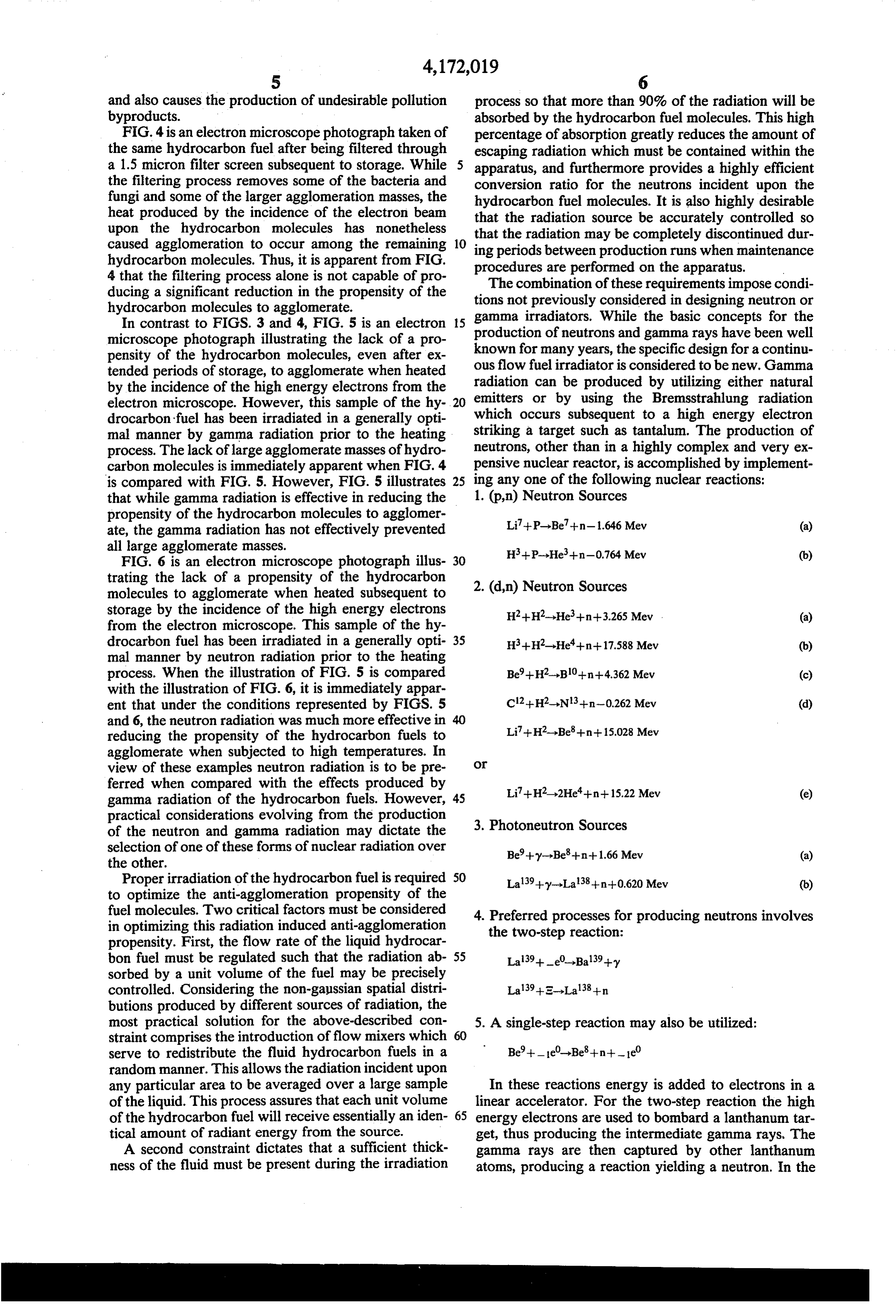
and also causes the production of undesirable pollution process so that more than 90% of the radiation will be byproducts. absorbed by the hydrocarbon fuel molecules. This high FIG. 4 is an electron microscope photograph taken of percentage of absorption greatly reduces the amount of the same hydrocarbon fuel after being filtered through escaping radiation which must be contained within the a 1.5 micron filter screen subsequent to storage. While apparatus, and furthermore provides a highly efficient the filtering process removes some of the bacteria and conversion ratio for the neutrons incident upon the fungi and some of the larger agglomeration masses, the hydrocarbon fuel molecules. It is also highly desirable heat produced by the incidence of the electron beam that the radiation source be accurately controlled so upon the hydrocarbon molecules has nonetheless that the radiation may be completely discontinued dur caused agglomeration to occur among the remaining 10 ing periods hydrocarbon molecules. Thus, it is apparent from FIG. procedures betweenare production runs when maintenance performed on the apparatus.
4 that the filtering process alone is not capable of pro The combination of these requirements impose condi ducing a significant reduction in the propensity of the tions not previously considered in designing neutron or hydrocarbon molecules to agglomerate.
In contrast to FIGS. 3 and 4, FIG. 5 is an electron 15 gamma irradiators. While the basic concepts for the microscope photograph illustrating the lack of a pro production of neutrons and gamma rays have been well pensity of the hydrocarbon molecules, even after ex ous known for many years, the specific design for a continu tended periods of storage, to agglomerate when heated flow fuel irradiator is considered to be new. Gamma by the incidence of the high energy electrons from the radiation can be produced by utilizing either natural electron microscope. However, this sample of the hy 20 emitters or by using the Bremsstrahlung radiation drocarbon fuel has been irradiated in a generally opti which occurs subsequent to a high energy electron mal manner by gamma radiation prior to the heating striking a target such as tantalum. The production of process. The lack of large agglomerate masses of hydro neutrons, other than in a highly complex and very ex carbon molecules is immediately apparent when FIG. 4 pensive nuclear reactor, is accomplished by implement is compared with FIG. 5. However, FIG. 5 illustrates 25 ing any one of the following nuclear reactions: that while gamma radiation is effective in reducing the 1. (p,n) Neutron Sources propensity of the hydrocarbon molecules to agglomer Li+P-Be7+n-1.646 Mev (a) ate, the gamma radiation has not effectively prevented all large agglomerate masses. H+P-He-n-0.764 Mev (b) FIG. 6 is an electron microscope photograph illus trating the lack of a propensity of the hydrocarbon 2. (d.,n) Neutron Sources molecules to agglomerate when heated subsequent to storage by the incidence of the high energy electrons H2+H2-He+n+3.265 Mew from the electron microscope. This sample of the hy drocarbon fuel has been irradiated in a generally opti 35 H+H2-He--n--17.588 Mev (b) mal manner by neutron radiation prior to the heating process. When the illustration of FIG. 5 is compared Be+H2--B10--n-4.362 Mev (c) with the illustration of FIG. 6, it is immediately appar ent that under the conditions represented by FIGS. 5 C12-i-H2-N13--n-0.262 Mew (d) and 6, the neutron radiation was much more effective in Li+H-Be+n+15,028 Mev reducing the propensity of the hydrocarbon fuels to agglomerate when subjected to high temperatures. In view of these examples neutron radiation is to be pre Or ferred when compared with the effects produced by Li+H 2He--n +15.22 Mev (e) gamma radiation of the hydrocarbon fuels. However, 45 practical considerations evolving from the production 3. Photoneutron Sources of the neutron and gamma radiation may dictate the selection of one of these forms of nuclear radiation over Be--y-Be+n+1.66 Mev (a) the other.
Proper irradiation of the hydrocarbon fuel is required 50 Lal-9-y-La3+n+0.620 Mev (b) to optimize the anti-agglomeration propensity of the fuel molecules. Two critical factors must be considered 4. Preferred processes for producing neutrons involves in optimizing this radiation induced anti-agglomeration the two-step reaction:
propensity. First, the flow rate of the liquid hydrocar bon fuel must be regulated such that the radiation ab 55 sorbed by a unit volume of the fuel may be precisely controlled. Considering the non-gaussian spatial distri Lal39--E-Lali8--n butions produced by different sources of radiation, the most practical solution for the above-described con 5. A single-step reaction may also be utilized: straint comprises the introduction of flow mixers which 60 serve to redistribute the fluid hydrocarbon fuels in a Be'--lie-Be--n--- e0 random manner. This allows the radiation incident upon any particular area to be averaged over a large sample In these reactions energy is added to electrons in a of the liquid. This process assures that each unit volume linear accelerator. For the two-step reaction the high of the hydrocarbon fuel will receive essentially an iden 65 energy electrons are used to bombard a lanthanum tar tical amount of radiant energy from the source. get, thus producing the intermediate gamma rays, The A second constraint dictates that a sufficient thick gamma rays are then captured by other lanthanum ness of the fluid must be present during the irradiation atoms, producing a reaction yielding a neutron. In the
Page 7
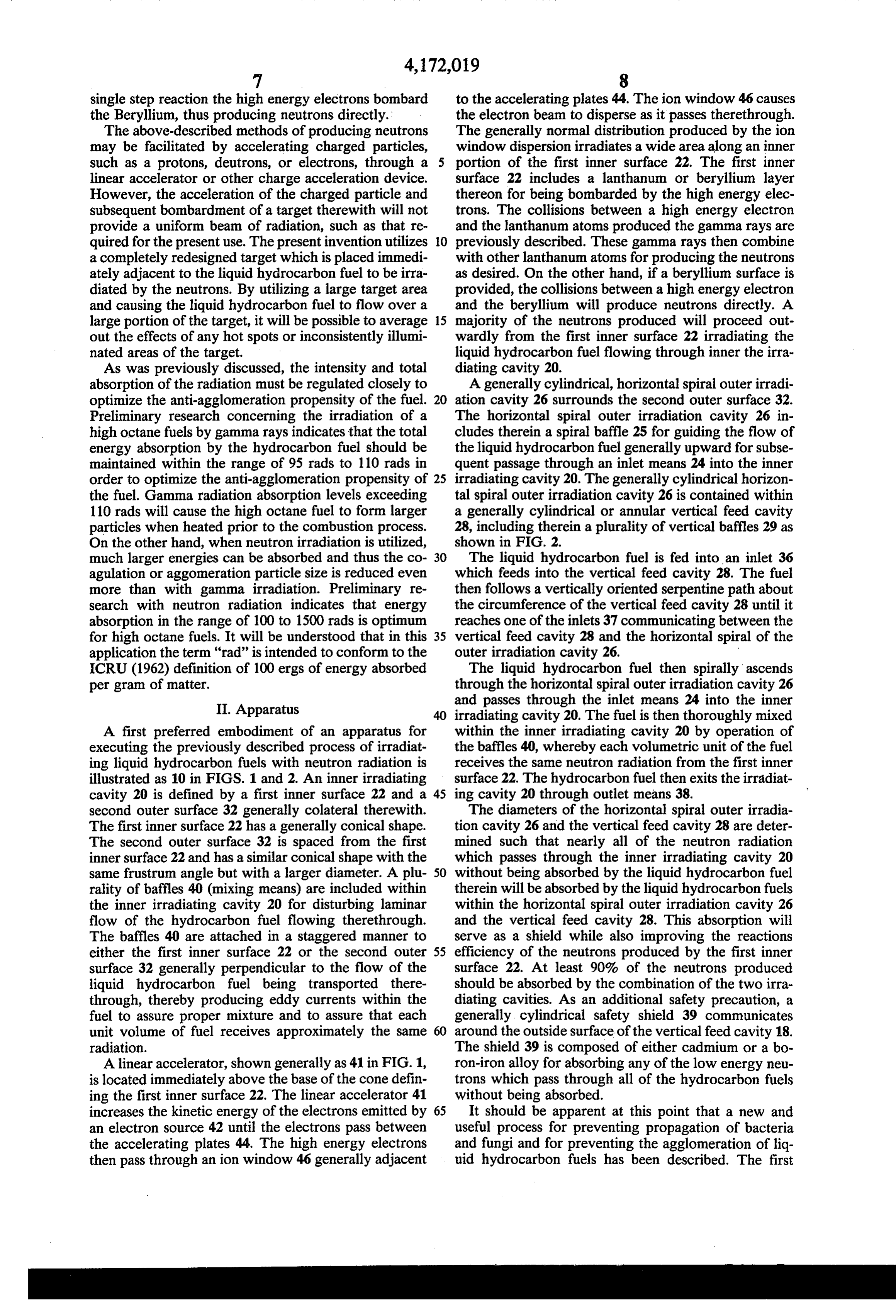
single step reaction the high energy electrons bombard to the accelerating plates 44. The ion window 46 causes the Beryllium, thus producing neutrons directly. the electron beam to disperse as it passes therethrough. The above-described methods of producing neutrons The generally normal distribution produced by the ion may be facilitated by accelerating charged particles, window dispersion irradiates a wide area along an inner such as a protons, deutrons, or electrons, through a 5 portion of the first inner surface 22. The first inner linear accelerator or other charge acceleration device. surface 22 includes a lanthanum or beryllium layer However, the acceleration of the charged particle and thereon for being bombarded by the high energy elec subsequent bombardment of a target therewith will not trons. The collisions between a high energy electron provide a uniform beam of radiation, such as that re and the lanthanum atoms produced the gamma rays are quired for the present use. The present invention utilizes O previously described. These gamma rays then combine a completely redesigned target which is placed immedi with other lanthanum atoms for producing the neutrons ately adjacent to the liquid hydrocarbon fuel to be irra as desired. On the other hand, if a beryllium surface is diated by the neutrons. By utilizing a large target area provided, the collisions between a high energy electron and causing the liquid hydrocarbon fuel to flow over a and the beryllium will produce neutrons directly. A large portion of the target, it will be possible to average 15 majority of the neutrons produced will proceed out out the effects of any hot spots or inconsistently illumi wardly from the first inner surface 22 irradiating the nated areas of the target. liquid hydrocarbon fuel flowing through inner the irra As was previously discussed, the intensity and total diating cavity 20.
absorption of the radiation must be regulated closely to A generally cylindrical, horizontal spiral outer irradi optimize the anti-agglomeration propensity of the fuel. 20 ation cavity 26 surrounds the second outer surface 32. Preliminary research concerning the irradiation of a The horizontal spiral outer irradiation cavity 26 in high octane fuels by gamma rays indicates that the total cludes therein a spiral baffle 25 for guiding the flow of energy absorption by the hydrocarbon fuel should be the liquid hydrocarbon fuel generally upward for subse maintained within the range of 95 rads to 110 rads in quent passage through an inlet means 24 into the inner order to optimize the anti-agglomeration propensity of 25 irradiating cavity 20. The generally cylindrical horizon the fuel. Gamma radiation absorption levels exceeding tal spiral outer irradiation cavity 26 is contained within 110 rads will cause the high octane fuel to form larger a generally cylindrical or annular vertical feed cavity particles when heated prior to the combustion process. 28, including therein a plurality of vertical baffles 29 as On the other hand, when neutron irradiation is utilized, shown in FIG. 2.
much larger energies can be absorbed and thus the co 30 The liquid hydrocarbon fuel is fed into an inlet 36 agulation or aggomeration particle size is reduced even which feeds into the vertical feed cavity 28. The fuel more than with gamma irradiation. Preliminary re then follows a vertically oriented serpentine path about search with neutron radiation indicates that energy the circumference of the vertical feed cavity 28 until it absorption in the range of 100 to 1500 rads is optimum reaches one of the inlets 37 communicating between the for high octane fuels. It will be understood that in this 35 vertical feed cavity 28 and the horizontal spiral of the application the term "rad" is intended to conform to the outer irradiation cavity 26.
ICRU (1962) definition of 100 ergs of energy absorbed The liquid hydrocarbon fuel then spirally ascends per gram of matter. through the horizontal spiral outer irradiation cavity 26 II. Apparatus and passes through the inlet means 24 into the inner irradiating cavity 20. The fuel is then thoroughly mixed
A first preferred embodiment of an apparatus for within the inner irradiating cavity 20 by operation of executing the previously described process of irradiat the baffles 40, whereby each volumetric unit of the fuel ing liquid hydrocarbon fuels with neutron radiation is receives the same neutron radiation from the first inner illustrated as 10 in FIGS. 1 and 2. An inner irradiating surface 22. The hydrocarbon fuel then exits the irradiat cavity 20 is defined by a first inner surface 22 and a 45 ing cavity 20 through outlet means 38. second outer surface 32 generally colateral therewith. The diameters of the horizontal spiral outer irradia The first inner surface 22 has a generally conical shape. tion cavity 26 and the vertical feed cavity 28 are deter The second outer surface 32 is spaced from the first mined such that nearly all of the neutron radiation inner surface 22 and has a similar conical shape with the which passes through the inner irradiating cavity 20 same frustrum angle but with a larger diameter. A plu 50 without being absorbed by the liquid hydrocarbon fuel rality of baffles 40 (mixing means) are included within therein will be absorbed by the liquid hydrocarbon fuels the inner irradiating cavity 20 for disturbing laminar within the horizontal spiral outer irradiation cavity 26 flow of the hydrocarbon fuel flowing therethrough. and the vertical feed cavity 28. This absorption will The baffles 40 are attached in a staggered manner to serve as a shield while also improving the reactions either the first inner surface 22 or the second outer 55 efficiency of the neutrons produced by the first inner surface 32 generally perpendicular to the flow of the surface 22. At least 90% of the neutrons produced liquid hydrocarbon fuel being transported there should be absorbed by the combination of the two irra through, thereby producing eddy currents within the diating cavities. As an additional safety precaution, a fuel to assure proper mixture and to assure that each generally cylindrical safety shield 39 communicates unit volume of fuel receives approximately the same around the outside surface of the vertical feed cavity 18. radiation. The shield 39 is composed of either cadmium or a bo A linear accelerator, shown generally as 41 in FIG. 1, ron-iron alloy for absorbing any of the low energy neu is located immediately above the base of the cone defin trons which pass through all of the hydrocarbon fuels ing the first inner surface 22. The linear accelerator 41 without being absorbed.
increases the kinetic energy of the electrons emitted by 65 It should be apparent at this point that a new and an electron source 42 until the electrons pass between useful process for preventing propagation of bacteria the accelerating plates 44. The high energy electrons and fungi and for preventing the agglomeration of liq then pass through an ion window 46 generally adjacent uid hydrocarbon fuels has been described. The first
Page 8
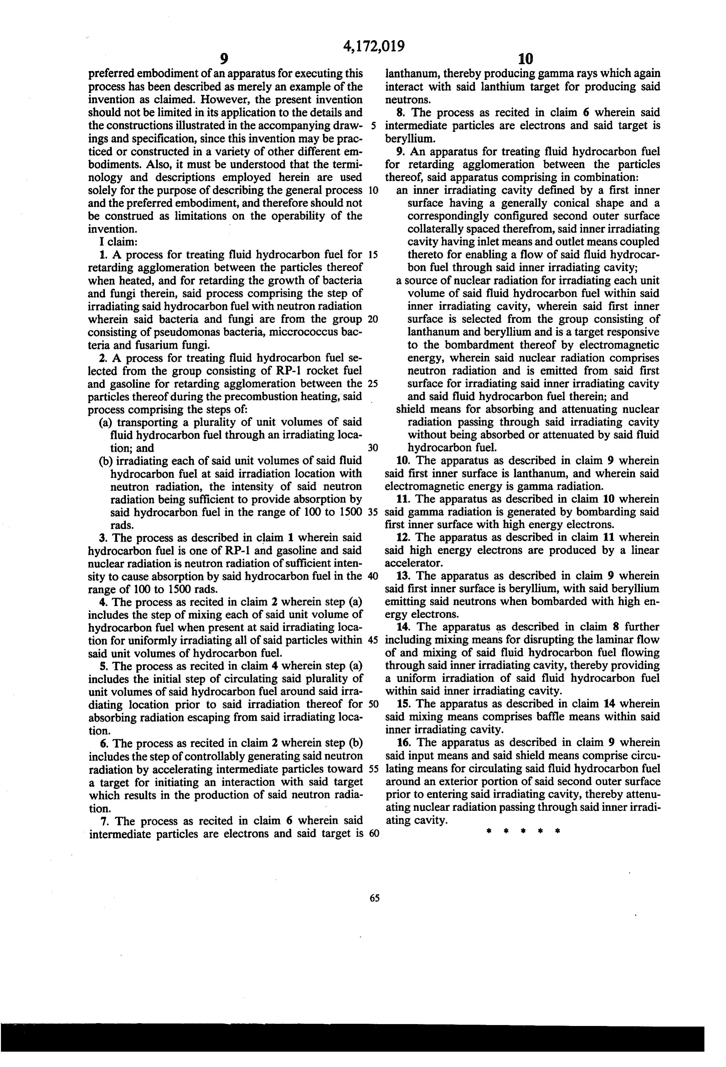
preferred embodiment of an apparatus for executing this lanthanum, thereby producing gamma rays which again process has been described as merely an example of the interact with said lanthium target for producing said invention as claimed. However, the present invention retros.
should not be limited in its application to the details and 8. The process as recited in claim 6 wherein said the constructions illustrated in the accompanying draw- 5 intermediate particles are electrons and said target is ings and specification, since this invention may be prac beryllium.
ticed or constructed in a variety of other different em 9. An apparatus for treating fluid hydrocarbon fuel bodiments. Also, it must be understood that the termi for retarding agglomeration between the particles nology and descriptions employed herein are used thereof, said apparatus comprising in combination: solely for the purpose of describing the general process 10 an inner irradiating cavity defined by a first inner and the preferred embodiment, and therefore should not surface having a generally conical shape and a be construed as limitations on the operability of the correspondingly configured second outer surface invention. collaterally spaced therefrom, said inner irradiating I claim: cavity having inlet means and outlet means coupled 1. A process for treating fluid hydrocarbon fuel for 15 thereto for enabling a flow of said fluid hydrocar retarding agglomeration between the particles thereof bon fuel through said inner irradiating cavity; when heated, and for retarding the growth of bacteria a source of nuclear radiation for irradiating each unit and fungi therein, said process comprising the step of volume of said fluid hydrocarbon fuel within said irradiating said hydrocarbon fuel with neutron radiation inner irradiating cavity, wherein said first inner wherein said bacteria and fungi are from the group 20 surface is selected from the group consisting of consisting of pseudomonas bacteria, miccrococcus bac lanthanum and beryllium and is a target responsive teria and fusarium fungi. to the bombardment thereof by electromagnetic 2. A process for treating fluid hydrocarbon fuel se energy, wherein said nuclear radiation comprises lected from the group consisting of RP-1 rocket fuel neutron radiation and is emitted from said first and gasoline for retarding agglomeration between the 25 surface for irradiating said inner irradiating cavity particles thereof during the precombustion heating, said and said fluid hydrocarbon fuel therein; and process comprising the steps of: shield means for absorbing and attenuating nuclear (a) transporting a plurality of unit volumes of said radiation passing through said irradiating cavity fluid hydrocarbon fuel through an irradiating loca without being absorbed or attenuated by said fluid tion; and 30 hydrocarbon fuel.
(b) irradiating each of said unit volumes of said fluid 10. The apparatus as described in claim 9 wherein hydrocarbon fuel at said irradiation location with said first inner surface is lanthanum, and wherein said neutron radiation, the intensity of said neutron electromagnetic energy is gamma radiation.
radiation being sufficient to provide absorption by 11. The apparatus as described in claim 10 wherein said hydrocarbon fuel in the range of 100 to 1500 35 said gamma radiation is generated by bombarding said rads. first inner surface with high energy electrons. 3. The process as described in claim 1 wherein said 12. The apparatus as described in claim 11 wherein hydrocarbon fuel is one of RP-1 and gasoline and said said high energy electrons are produced by a linear nuclear radiation is neutron radiation of sufficient inten accelerator.
sity to cause absorption by said hydrocarbon fuel in the 40 13. The apparatus as described in claim 9 wherein range of 100 to 1500 rads. said first inner surface is beryllium, with said beryllium 4. The process as recited in claim 2 wherein step (a) emitting said neutrons when bombarded with high en includes the step of mixing each of said unit volume of ergy electrons.
hydrocarbon fuel when present at said irradiating loca 14. The apparatus as described in claim 8 further tion for uniformly irradiating all of said particles within 45 including mixing means for disrupting the laminar flow said unit volumes of hydrocarbon fuel. of and mixing of said fluid hydrocarbon fuel flowing 5. The process as recited in claim 4 wherein step (a) through said inner irradiating cavity, thereby providing includes the initial step of circulating said plurality of a uniform irradiation of said fluid hydrocarbon fuel unit volumes of said hydrocarbon fuel around said irra within said inner irradiating cavity. diating location prior to said irradiation thereof for 50 15. The apparatus as described in claim 14 wherein absorbing radiation escaping from said irradiating loca said mixing means comprises baffle means within said tion. inner irradiating cavity.
6. The process as recited in claim 2 wherein step (b) 16. The apparatus as described in claim 9 wherein includes the step of controllably generating said neutron said input means and said shield means comprise circu radiation by accelerating intermediate particles toward 55 lating means for circulating said fluid hydrocarbon fuel a target for initiating an interaction with said target around an exterior portion of said second outer surface which results in the production of said neutron radia prior to entering said irradiating cavity, thereby attenu tion. ating nuclear radiation passing through said inner irradi 7. The process as recited in claim 6 wherein said ating cavity.
intermediate particles are electrons and said target is 60
Page 9
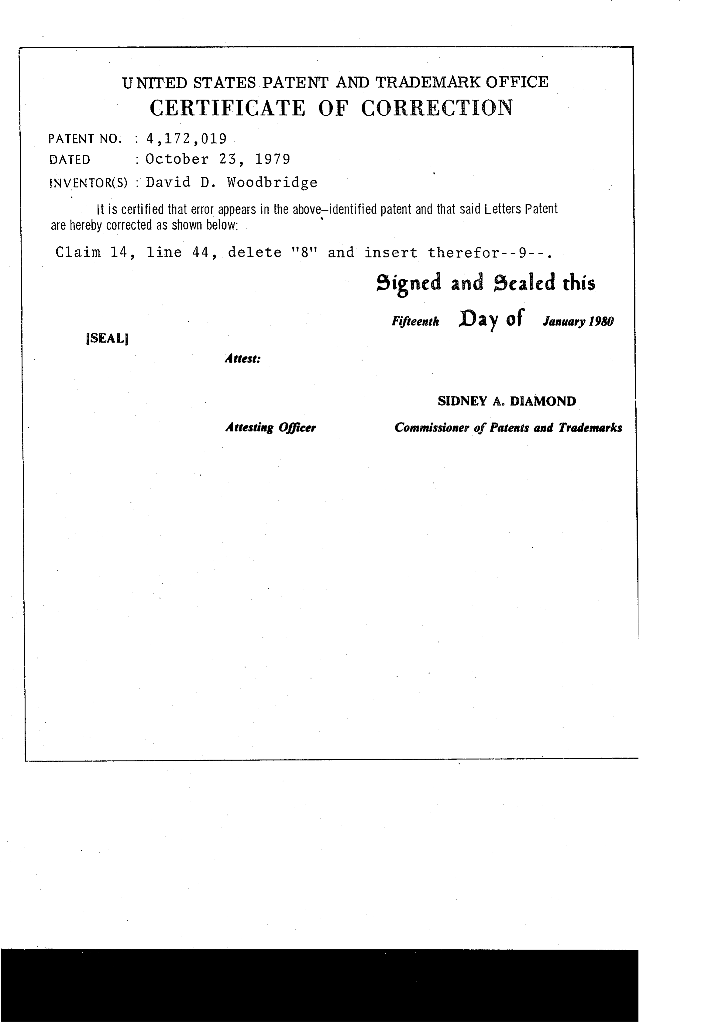
UNITED STATES PATENT AND TRADEMARK OFFICE
CERTIFICATE OF CORRECTION
INVENTOR(S) : David D. Woodbridge it is certified that error appears in the above-identified patent and that said Letters Patent are hereby corrected as shown below:
Claim 14, line 44, delete '8' and insert therefor--9--. eigned and Sealed this
Fifteenth D 2 y of January 1980
SEAL
Attest:
SIDNEY A. DAMOND
Attesting Officer Commissioner of Patents and Trademarks
Page 10
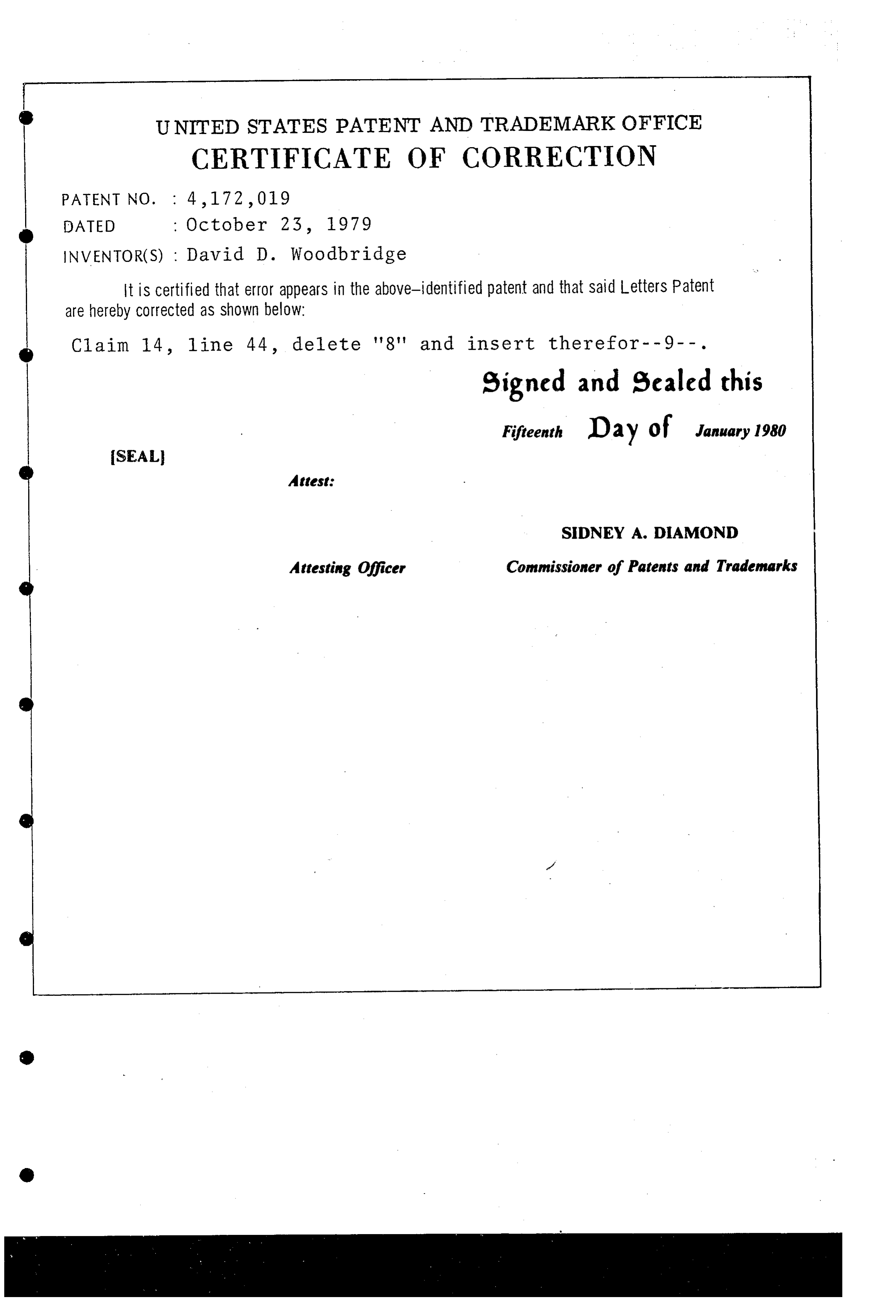
UNITED STATES PATENT AND TRADEMARK OFFICE
CERTIFICATE OF CORRECTION
INVENTOR(S) : David D. Woodbridge
It is Certified that error appears in the above-identified patent and that said Letters Patent are hereby corrected as shown below:
C) Claim 14, line 44, delete '8' and insert therefor--9--. signed and sealed this
Fifteenth Day of January 1980
SEAL
Attest:
SIDNEY A. DAMOND
Attesting Officer Commissioner of Patents and Trademarks
Provenance
- Collection
- Cited prior art
- Original PDF
- patentimages.storage.googleapis.com →
- Filed
- 1977-11-23
- Pages
- 10
- Method
- pdftotext (the PDF's own text layer) + pdftoppm 300dpi page scans
- Source
- Google Patents bibliographic record
- Granted
- 1979-10-23
- Inventors
- David D. Woodbridge
- Transcribed from
- patentimages.storage.googleapis.com →