patent · US3392530
Method of preventing hydrate formation in underground storage caverns
16 July 1968
Page 1
July 16, 1968 METHOD OF PREVENTING
C. T. BRANDT
HYDRATE FORMATION IN
UNDERGROUND STORAGE CAVERNS
HYDROCARBON
GAS SOURCE
COMPRESSOR
COMPRESSOR
:A; CC REFRIGERATION PLANT 26, 22
INERT
2s2 32&2&2&2&ax2N/N SAS Rasar SSSS):
- - -- - - - - - - - - -
S& $y SS3 NY
S 2O
INVENTOR.
CARL. T. BRANDT
ATTORNEYS
Page 2
United States Patent Office 3,392,530 Patented July 16, 1968
3,392,530 ing formation in a manner such that the formation of hy dates in the cavern is prevented.
METHOD OF PREVENTING HYDRATE FORMA.
TION IN UNDERGROUND STORAGE CAVERNS These and other objects will be fulfilled by the methods Carl T. Brandt, Tulsa, Okla., assignor to Fenix & Scisson, of the invention to be now described, the description being Inc., Tulsa, Okla., a corporation of Oklahoma taken with reference to the drawing which is a diagram. Filed July 23, 1965, Ser. No. 474,267 matic representation of a cavern formed in the earth in 3 Claims. (C. 61-5) cluding the mechanisms utilized to practice the method of this invention.
This invention may be described as a method of pre
ABSTRACT OF THE DISCLOSURE 10 venting hydrate formation in a cavern formed in an under This invention provides a method of preventing hydrate ground permeable water bearing formation. More par formation in an underground storage cavern formed in a ticularly, but not by way of limitation, the invention may water bearing permeable formation. The method includes be described as a method of sealing a cavern formed in the steps of pressuring the cavern with an inert gas to a 15 a permeable water bearing underground formation com pressure at least equal to the hydrostatic pressure of water prising the steps of introducing an inert non-hydrate form tending to enter the cavern to stop the flow of water into ing gas into the cavern to purge air from the cavern, pres the cavern, injecting into the cavern a cooled compressed Suring the cavern with the inert gas to a pressure at least high vapor pressure petroleum product while maintain equal to the hydrostatic pressure of water tending to enter ing the pressure within the cavern, and maintaining the 20 the cavern to stop the flow of water into the cavern, in pressure within the cavern until the walls thereof are freeze jecting high vapor pressure hydrocarbon gas which has sealed, been cooled below the freezing point of water into the cavern to purge the inert gas therefrom and at the same time maintaining the gas pressure within the cavern at
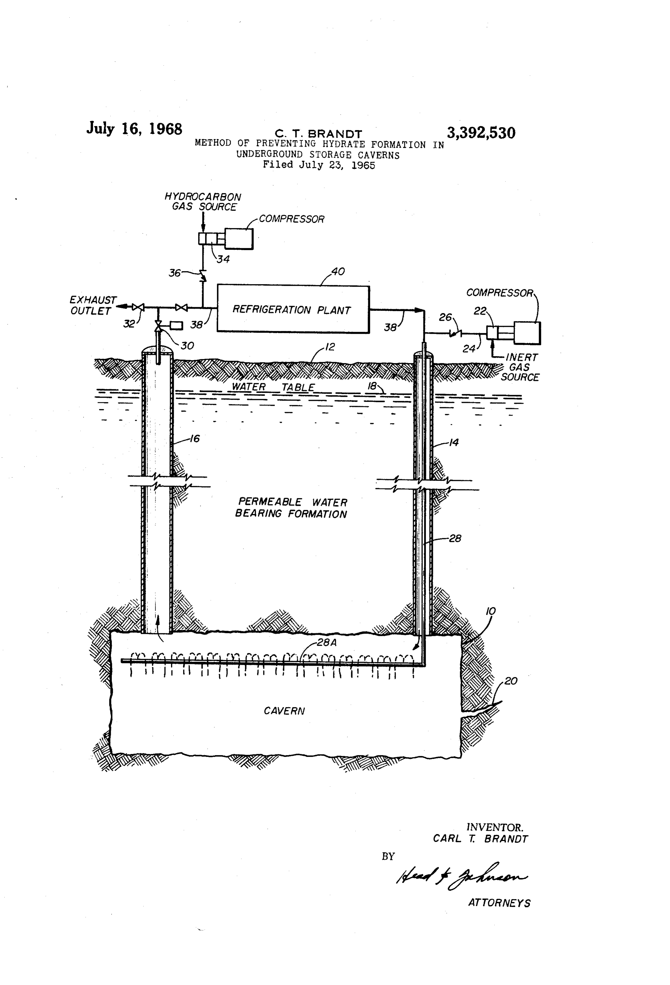
This invention relates to a method of preventing hy 25 least equal to hydrostatic pressure of water tending to drate formations in underground storage caverns. More enter the cavern, and circulating the hydrocarbon gas particularly, the invention relates to a method of sealing through the cavern until the walls are freeze-sealed. the walls of an underground storage cavern formed in Referring now to the drawing, a cavern 10 is shown, permeable water bearing formations. the cavern having been excavated in a porous water bear In recent years the use of underground caverns has be ing formation. The cavern is connected to the surface 12 come an expedient means of storing large volumes of 30 of the earth by means of shafts 14 and 16. The water table liquids. One of the reasons is that it has been learned that in the formation, the top of which is indicated by the nu liquids, such as liquefied petroleum gas, are more eco meral 18, is usually below the earth's surface and is the nomically stored in underground caverns than in above point at which hydrostatic pressure in the earth's forma ground vessels. A frauently used method of providing tion begins. The hydrostatic pressure of water table 18 underground storage caverns is to mine the caverns in 35 tends to cause water to flow into the cavern 10. Such salt formations, the mining taking place either by phys Water flow may take place either through the pores of the ically removing the salt or by solution mining. Such salt permeable formation in which the cavern has been dug formation is non-porous and after the cavern is formed, the or through fissures in the formation, such as indicated by numeral 20.
offers a substantially leakproof underground enclosure for 40 the storage of liquids. One problem, however, is that the When excavation of cavern 12 is completed and before occurrence of large salt formations in certain geographical the method of this invention is undertaken to seal the areas are rare so that in many instances such formations cavern wall, all water in the cavern is pumped out through cannot be found in the places where underground stor either shaft 14 or 16; the equipment utilized for such age is desired. This means that some other system is re 45 pumping purposes is not shown since such forms no part quired for providing leakproof underground enclosures. of this invention.
One method of providing such enclosures is that of After the excess water has ben removed the first step digging caverns in porous water bearing formations and, of this invention is to purge the air within the cavern upon completion of the caverns, freezing the water in 10 to reduce the oxygen content thereof so that sub the walls to form sealed enclosures. Whereas large salt 50 Sequent introduction of hydrocarbon gases will not create deposits where storage caverns can be located are rela an explosive mixture. Such inert gas is pressured by com tively rare, most geographical areas afford porous under pressor 22, the pressured gas flowing through line 24 and ground water bearing formations. In addition to leakage, valve 26, through shaft 14 and into the cavern. To a problem which has plagued the use of water bearing for mations for the storage of certain high vapor pressure hy 55 facilitate may distribution of gas into the cavern, shaft 14 contain a string of tubing 28. Tubing 28 bends with drocarbon products, or mixtures thereof, is that when in the cavern to extend horizontally through the length these liquids are delivered into a cavern containing water, of the cavern, the extending portion 28A being provided solid hydrates may be formed. The formation of hydrates causes two difficulties, that is, first, hydrate formation can with numerous perforations. The use of the tubing 28 materially reduce the storage capacity of the cavern, and, 60 and particularly the perforated extending horizontal por second hydrates can block openings to prevent the flow of tion 28A is by way of example only and is illustrative fluid into or out of the caverns. only, the use of such tubing is not essential to the basic The basic object of this invention is to provide a means methods of the invention. . of preventing hydrate formations in caverns utilized to The inert gas from compressor 22 fills the cavern 1 store liquefied hydrocarbons. A still more particular ob and forces air trapped in the cavern up through shaft ject of this invention is to provide a method of sealing a 65 16, past control valve 30 and exhaust valve 32 to the cavern formed in a permeable underground water bear atmosphere. When the oxygen content of the air, forced
Page 3
out the exhaust outlet, falls below the point wherein bon gas may then be vented and the cavern put to use as danger of explosion may occur, the control valve 30 and a storage facility for liquefied petroleum gas or some the exhaust valve 32 are closed. Inert gas is continued other gas having similar property. The cavern will be to be injected into the cavern 10 until the pressure there sealed as long as the walls are kept below freezing tem of rises to the point equal to the hydrostatic pressure 5 perature which is accomplished by previously known of water tending to enter the cavern. means, such as circulating a refrigerant therethrough, not The hydrosatic pressure of water tending to enter the forming a part of this invention.
cavern is usually directly related to the height of the In this description the expression "hydrocarbon gas' water table 18 above the cavern. The flow of water into or "high vapor pressure hydrocarbon gas' means any the cavern is directly related to the difference between O hydrocarbon gas having a vapor pressure of butane or the hydrostatic pressure of the water and the pressure higher. Inert gas as used herein includes any gas which in the cavern. As the pressure in the cavern increases is noncombustible and nonhydrate forming, such as nitro the flow diminishes and when the hydrostatic pressure gen or flue gas.
in the cavern exactly equals the hydrostatic pressure of While in this description two shafts 14 and 16 are water tending to enter the cavern the water flow stops. 15 illustrated for purposes of simplicity it can be seen that If the hydrostatic pressure in the cavern exceeds the hy the operation can easily be carried out by the use of drostatic pressure of water tending to enter the cavern a plurality of lengths of tubing located in a single shaft, then water would be forced away from the cavern walls. the number of shafts not forming a part of the method In the method of this invention it is desirable that the of this invention. This invention provides a means of hydrostatic pressure of the gas in the cavern be as near 20 freeze sealing the walls of a cavern in a manner wherein as possible to the hydrostatic pressure of the water tend it is not necessary to pump water from the cavern as ing to enter the cavern so that all water flow into the the freezing process is taking place. This is an important cavern ceases, but, at the same time, the water is not advantage in that prior methods have encountered con forced from the walls. This balanced force maintains siderable difficulty in attempting to excavate water while the walls as near as possible in saturated condition. The 25 hydrocarbons are being injected due to the hydrates block pressure of gas necessary within the cavern to equalize ing the water evacuation lines.
the hydrostatic presure of water is best determined be While this invention has been described with a certain fore the steps of the method of this invention are under degree of particularity it is manifest that many changes taken. If the height of the water table is known, such may be made in the details of construction and in the hydrostatic pressure can usually be accurately and simply 30 sequence of steps employed by the arrangement of com computed. ponents, without departing from the spirit and Scope of As previously stated, inert gas is forced from com this disclosure.
pressor 22, through line 24 and shaft 14 into the cavern What is claimed:
to raise the hydrostatic pressure to that preventing the 1. A method of preventing hydrate formation in a flow of water into the cavern. This can be accomplished 35 cavern formed in a water bearing permeable formation relatively quickly, the time depending upon the capacity comprising the steps of:
of the compressor 22. In any event, the raising of the (1) pressuring the cavern with an inert gas to a pres pressure in the cavern to equal the hydrostatic pres sure at least the hydrostatic pressure of water tending sure of the water tending to enter the cavern can be to enter the cavern to stop the flow of water into the accomplished relatively quickly thereby reducing the total 40 CaVern;
water in the cavern. (2) injecting into the cavern a cooled compressed high When the pressure balance of the inert gas with the vapor pressure petroleum product while maintaining water tending to enter the cavern is achieved the next the pressure within the cavern; and step is to quickly freeze the walls of the cavern. It is (3) maintaining the pressure within the cavern until well known that running water is very difficult to freeze 45 the walls thereof are freeze sealed. whereas still water is easily frozen by lowering the tem 2. A method of sealing a cavern formed in a permeable perature. The next basic step of this invention is to quick water bearing underground formation comprising: ly freeze the water in the porous formations forming introducing an inert non-hydrate forming gas into said the wall of the cavern. This is accomplished by inject cavern to purge air from the cavern; ing a high vapor pressure hydrocarbon gas, such as pressuring the cavern with said inert non-hydrate form natural gas, into the cavern. This is achieved by com ing gas to a pressure at least equal to the hydrostatic pressor 34 forcing the gas through check valve 36 and pressure of water tending to enter the cavern to stop line 38, down shaft 14 and into the cavern 10. As the flow of water into the cavern; previously indicated, in the preferred arrangement, line injecting high vapor pressure hydrocarbon gas cooled 38, as did line 24, connects with a tubing 28 having a 55 below the freezing point of water into the cavern to horizontally extending perforated portion 28A. The hy purge the inert gas therefrom and at the same time drocarbon gas purges the inert gas contained in the maintaining the gas pressure within the cavern above cavern. The inert gas is permitted to escape out of the the hydrostatic pressure of water tending to enter cavern through control valve 30 and exhaust valve 32. the cavern;
Control valve 30 is of the type which maintains a 60 circulating the cooled gas through the cavern until the back pressure within the cavern at the preselected hydro walls thereof are freeze sealed. static pressure to prevent water flow into the cavern. 3. A method of sealing a cavern formed in a permeable The hydrocarbon gas is cooled below the freezing point water bearing underground formation comprising: of water by refrigeration plant 40 before it enters into introducing an inert non-hydrate forming gas into said the cavern 10. Thus the hydrocarbon gas entering the cavern to purge air from the cavern; cavern causes the water in the porous walls of the cavern increasing the pressure of the inert gas to substantially to freeze, sealing the cavern. If necessary, the hydrocar the hydrostatic pressure of water tending to enter bon gas can be continuously recirculated through the the cavern to stop the flow of water into the cavern; refrigeration plant 40 as long as necessary to completely injecting high vapor pressure hydrocarbon gas into the freeze the walls of cavern 10, at the same time main 70 cavern at a pressure thereof substantially equal to taining the pressure within the cavern equal to the pre the hydrostatic pressure of water tending to enter the selected hydrostatic pressure to prevent water flow into cavern to continue to prevent the flow of water into the cavern. the cavern; and
The circulation of the hydrocarbon gas continues until circulating cooled hydrocarbon gas through the cavern the walls are completely freeze sealed. The hydrocar 75 While maintaining the hydrostatic pressure therein
Page 4
sufficient to prevent water flow into the cavern until 3,062,012 11/1962 Allen ---------------- 61-.5 the walls of the cavern are frozen. 3,205,665 9/1965 Van Horn ----------- 61-.5 Ref Cited 3,296,805 1/1967 Graham -------------- 61-.5 UNITED s Prents 5 FOREIGN PATENTS 2,932,170 4/1960 Patterson et al. ------- 61-.5 111,569 3/1962 Pakistan. 2,961,841 11/1960 Giles -------------- 61-.5 X EARL J. WITMER, Primary Examiner.
Provenance
- Collection
- Cited prior art
- Original PDF
- patentimages.storage.googleapis.com →
- Filed
- 1965-07-23
- Pages
- 4
- Method
- pdftotext (the PDF's own text layer) + pdftoppm 300dpi page scans
- Source
- Google Patents bibliographic record
- Granted
- 1968-07-16
- Inventors
- Carl T Brandt; Fenix and Scisson Inc
- Transcribed from
- patentimages.storage.googleapis.com →