patent · US3658123
Apparatus for controlling the temperature of a heat exchange medium
25 April 1972
Page 1 — bibliographic record
United States Patent (15) 3,658,123 Root (45) Apr. 25, 1972
54). APPARATUS FOR CONTROLLING THE
TEMPERATURE OF A HEAT Primary Examiner-Charles Sukalo
EXCHANGEMEDIUM Attorney-Head & Johnson 72 Inventor: Donald S. Root, 3830 South Cincinnati, 57 ABSTRACT
(22 Filed: Oct. 19, 1970 An apparatus for controlling the temperature of a heat exchange medium in a reverse cycle heat pump system in 21 Appl. No.: 82,019 cludes within a closed heat exchange medium recirculating path thermostatically controlled heater mount elements and (52) U.S. Cl................................................... 165/22, 165/45 heat rejection panels. The heat rejection panels are cooled by 5ll Int. Cl............................................................. F24f 3100 both air flow and evaporative water system which incor 58) Field of Search........................................ 165/22, 50, 45 porates a header having elongated members which discharge coolant onto the heat exchange panels through a continuous 56) References Cited slot whereby a water curtain is formed to completely wet the heat rejection panel surfaces. A storage reservoir can be util
UNITED STATES PATENTS ized to conserve the energy of the heat exchange medium. 2,715,514 8/1955 Stair........................................ 165/22 6 Claims, 5 Drawing Figures
Page 2
Drawing sheet — no readable text.
Page 3
Drawing sheet — no readable text.
Page 4
Drawing sheet — no readable text.
Page 5
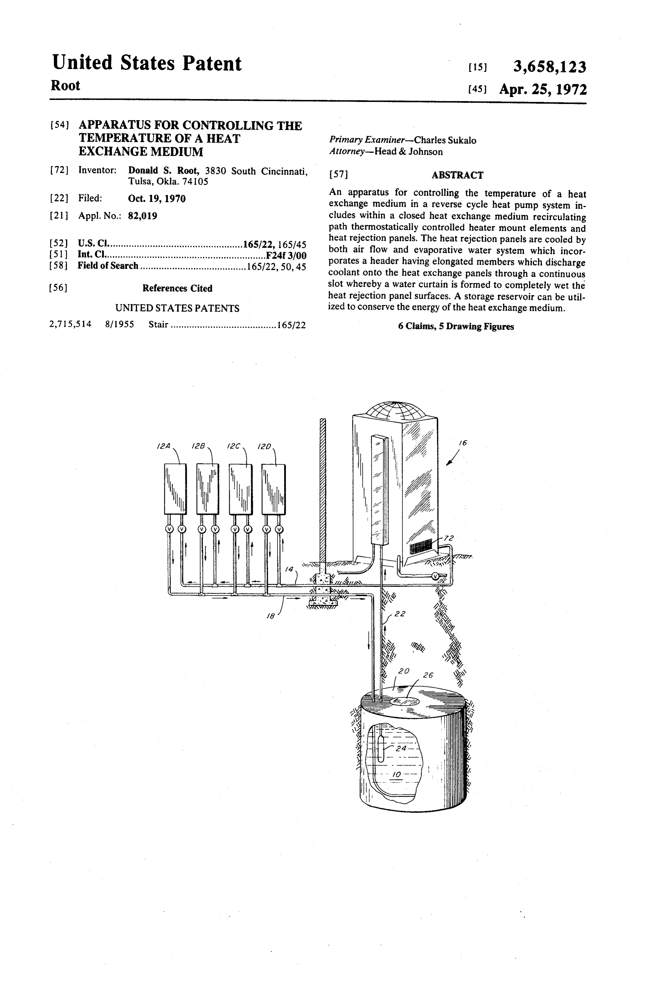
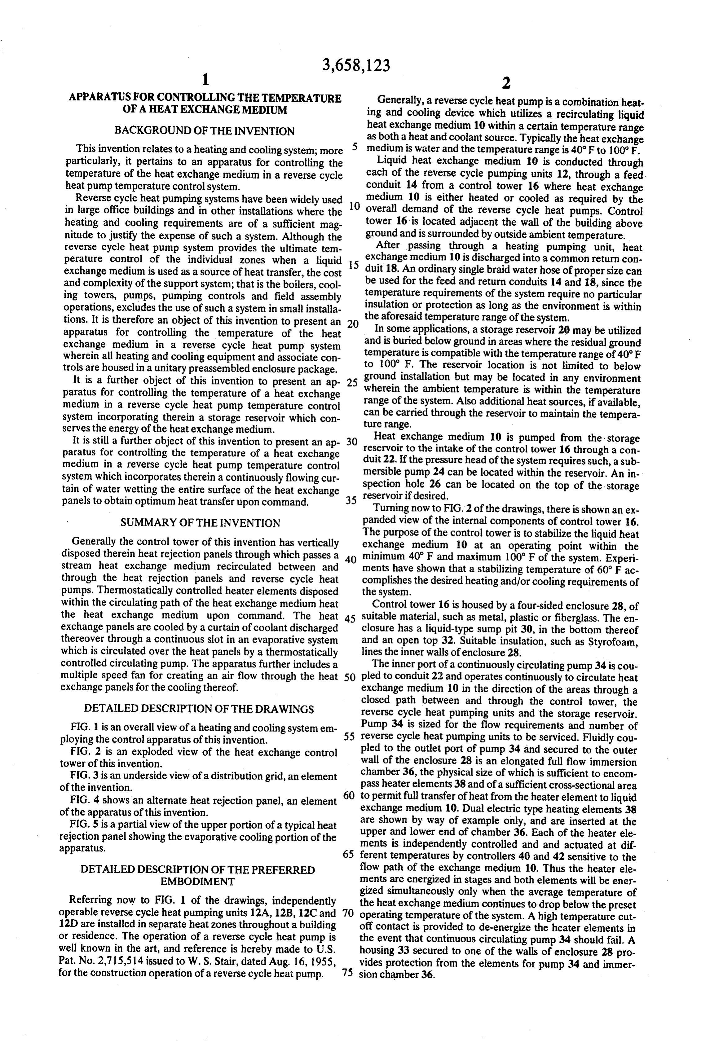
APPARATUS FOR CONTROLLING THE TEMPERATURE Generally, a reverse cycle heat pump is a combination heat OFA HEAT EXCHANGEMEDUM ing and cooling device which utilizes a recirculating liquid BACKGROUND OF THE INVENTION heat exchange medium 10 within a certain temperature range as both a heat and coolant source. Typically the heat exchange
This invention relates to a heating and cooling system; more medium is water and the temperature range is 40°F to 100°F. particularly, it pertains to an apparatus for controlling the Liquid heat exchange medium 10 is conducted through temperature of the heat exchange medium in a reverse cycle each of the reverse cycle pumping units 12, through a feed heat pump temperature control system. conduit 14 from a control tower 16 where heat exchange Reverse cycle heat pumping systems have been widely used 10 medium 10 is either heated or cooled as required by the in large office buildings and in other installations where the overall demand of the reverse cycle heat pumps. Control heating and cooling requirements are of a sufficient mag tower 16 is located adjacent the wall of the building above nitude to justify the expense of such a system. Although the ground and is surrounded by outside ambient temperature. reverse cycle heat pump system provides the ultimate tem After passing through a heating pumping unit, heat perature control of the individual zones when a liquid 5 exchange medium 10 is discharged into a common return con exchange medium is used as a source of heat transfer, the cost duit 18. An ordinary single braid water hose of proper size can and complexity of the support system; that is the boilers, cool be used for the feed and return conduits 14 and 18, since the ing towers, pumps, pumping controls and field assembly temperature requirements of the system require no particular operations, excludes the use of such a system in small installa insulation or protection as long as the environment is within tions. It is therefore an object of this invention to present an 20 the aforesaid temperature range of the system. apparatus for controlling the temperature of the heat In some applications, a storage reservoir 20 may be utilized exchange medium in a reverse cycle heat pump system and is buried below ground in areas where the residual ground wherein all heating and cooling equipment and associate con to temperature is compatible with the temperature range of 40°F trols are housed in a unitary preassembled enclosure package. 100 F. The reservoir location is not limited to below It is a further object of this invention to present an ap 25 ground installation but may be located in any environment paratus for controlling the temperature of a heat exchange wherein the ambient temperature is within the temperature medium in a reverse cycle heat pump temperature control range of the system. Also additional heat sources, if available, system incorporating therein a storage reservoir which con ture can be carried through the reservoir to maintain the tempera serves the energy of the heat exchange medium. range.
It is still a further object of this invention to present an ap 30 Heat exchange medium 10 is pumped from the storage paratus for controlling the temperature of a heat exchange duit reservoir to the intake of the control tower 16 through a con medium in a reverse cycle heat pump temperature control 22. If the pressure head of the system requires such, a sub system which incorporates therein a continuously flowing cur spection mersible pump 24 can be located within the reservoir. An in tain of water wetting the entire surface of the heat exchange reservoir ifhole 26 can be located on the top of the storage desired.
panels to obtain optimum heat transfer upon command. 35
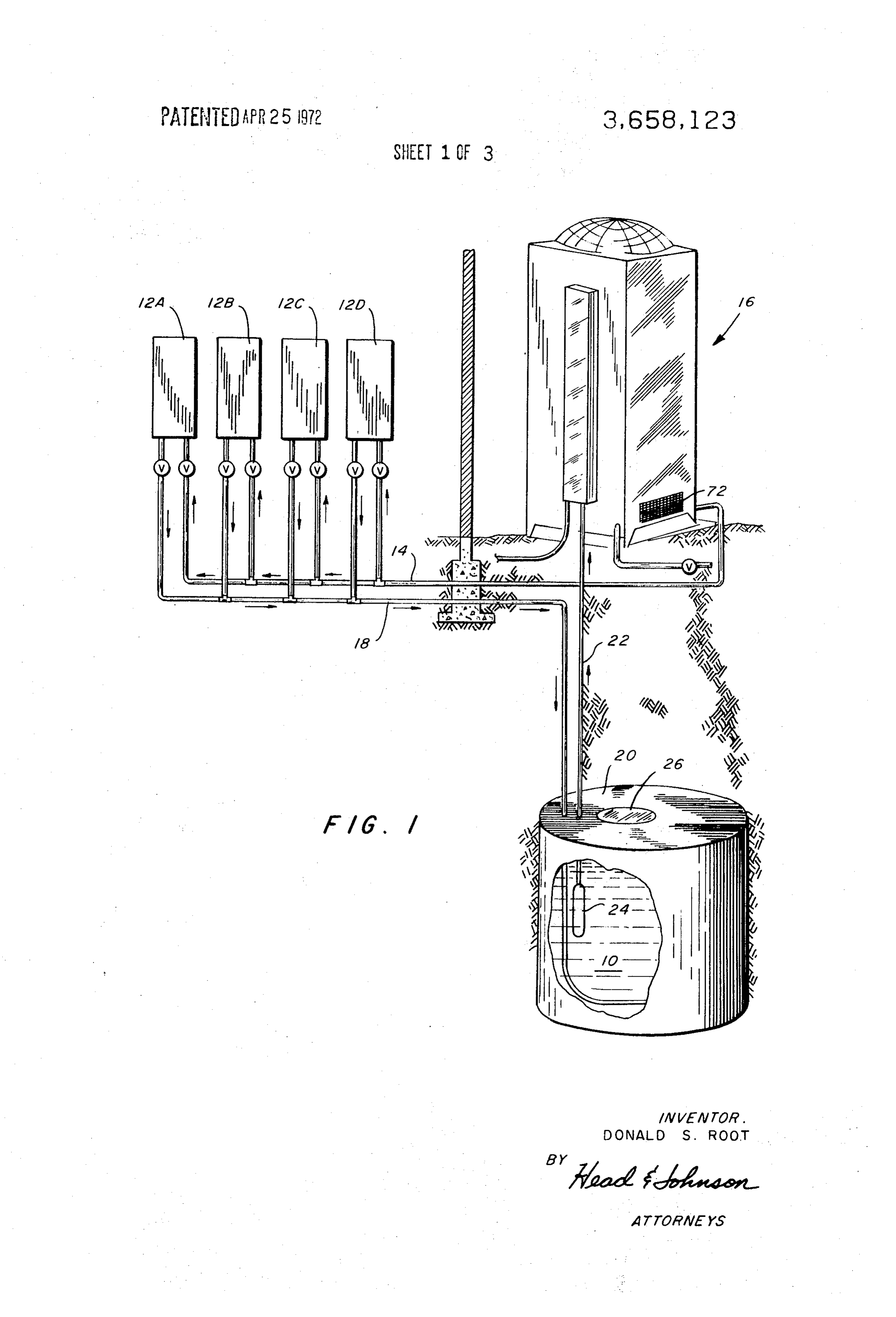
Turning now to FIG. 2 of the drawings, there is shown an ex
SUMMARY OF THE INVENTION panded view of the internal components of control tower 16. The purpose of the control tower is to stabilize the liquid heat
Generally the control tower of this invention has vertically exchange medium 10 at an operating point within the disposed therein heat rejection panels through which passes a 40 minimum 40° F and maximum 100 F of the system. Experi stream heat exchange medium recirculated between and ments have shown that a stabilizing temperature of 60° F ac through the heat rejection panels and reverse cycle heat complishes the desired heating and/or cooling requirements of pumps. Thermostatically controlled heater elements disposed the system.
within the circulating path of the heat exchange medium heat Control tower 16 is housed by a four-sided enclosure 28, of the heat exchange medium upon command. The heat 45 suitable material, such as metal, plastic or fiberglass. The en exchange panels are cooled by a curtain of coolant discharged closure has a liquid-type sump pit 30, in the bottom thereof thereover through a continuous slot in an evaporative system and an open top 32. Suitable insulation, such as Styrofoam, which is circulated over the heat panels by a thermostatically lines the inner walls of enclosure 28.
controlled circulating pump. The apparatus further includes a The inner port of a continuously circulating pump 34 is cou multiple speed fan for creating an air flow through the heat 50 pled to conduit 22 and operates continuously to circulate heat exchange panels for the cooling thereof. exchange medium 10 in the direction of the areas through a DETAILED DESCRIPTION OF THE DRAWINGS closed path between and through the control tower, the reverse cycle heat pumping units and the storage reservoir.
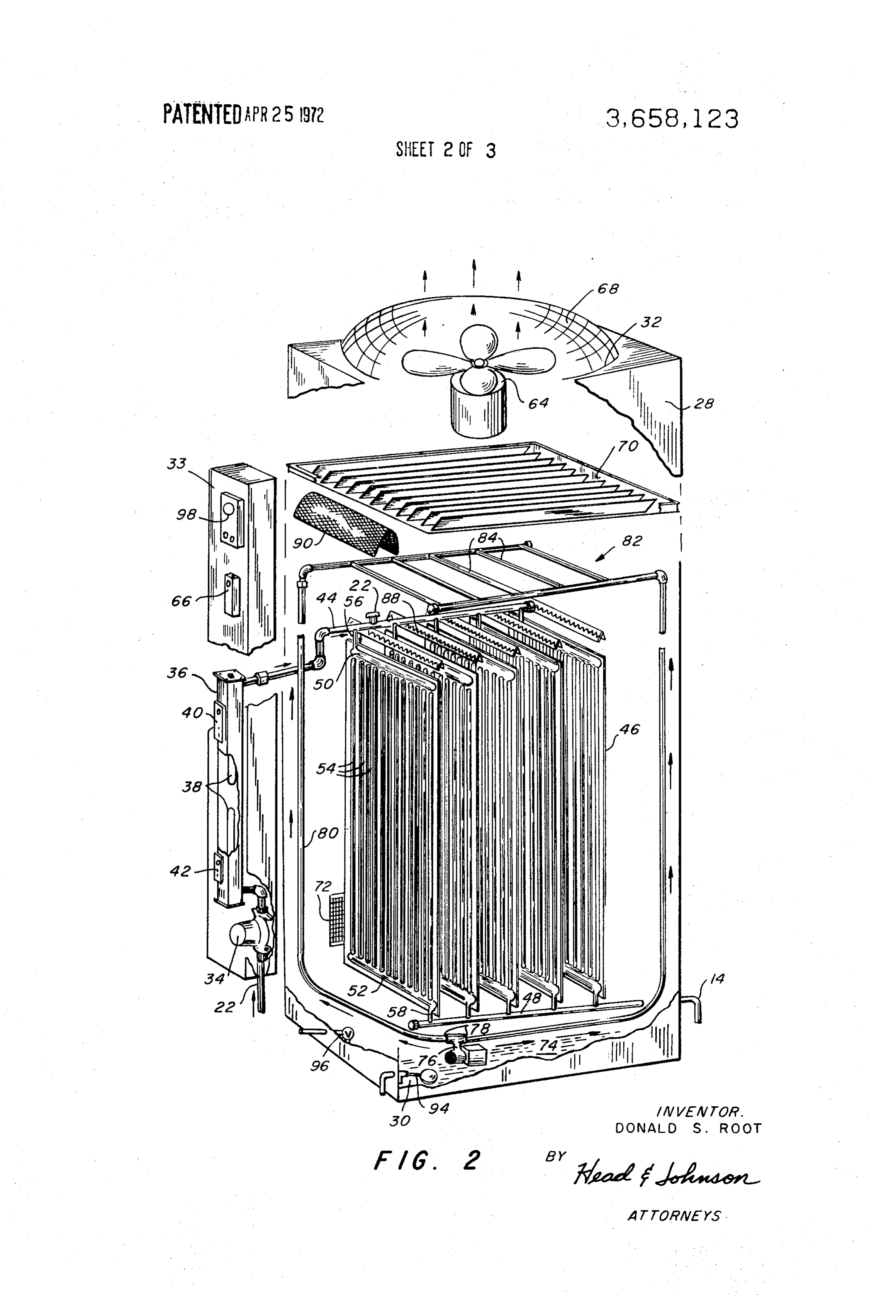
FIG. 1 is an overall view of a heating and cooling system en 55 Pump 34 is sized for the flow requirements and number of ploying the control apparatus of this invention. reverse cycle heat pumping units to be serviced. Fluidly cou FIG. 2 is an exploded view of the heat exchange control pled to the outlet port of pump 34 and secured to the outer tower of this invention. wall of the enclosure 28 is an elongated full flow immersion FIG. 3 is an underside view of a distribution grid, an element chamber 36, the physical size of which is sufficient to encom of the invention. pass heater elements 38 and of a sufficient cross-sectional area FIG. 4 shows an alternate heat rejection panel, an element 60 to permit full transfer of heat from the heater element to liquid of the apparatus of this invention. exchange medium 10. Dual electric type heating elements 38 FIG. 5 is a partial view of the upper portion of a typical heat are shown by way of example only, and are inserted at the rejection panel showing the evaporative cooling portion of the ments upper and lower end of chamber 36. Each of the heater ele apparatus. is independently controlled and and actuated at dif 65 ferent temperatures by controllers 40 and 42 sensitive to the
DETAILED DESCRIPTION OF THE PREFERRED flow path of the exchange medium 10. Thus the heater ele EMBODIMENT ments are energized in stages and both elements will be ener gized simultaneously only when the average temperature of
Referring now to FIG. 1 of the drawings, independently the heat exchange medium continues to drop below the preset operable reverse cycle heat pumping units 12A, 12B, 12C and 70 operating temperature of the system. A high temperature cut 12D are installed in separate heat zones throughout a building off contact is provided to de-energize the heater elements in or residence. The operation of a reverse cycle heat pump is the event that continuous circulating pump 34 should fail. A well known in the art, and reference is hereby made to U.S. housing 33 secured to one of the walls of enclosure 28 pro Pat. No. 2,715,514 issued to W. S. Stair, dated Aug. 16, 1955, vides protection from the elements for pump 34 and immer for the construction operation of a reverse cycle heat pump. 75 sion chamber 36.
Page 6
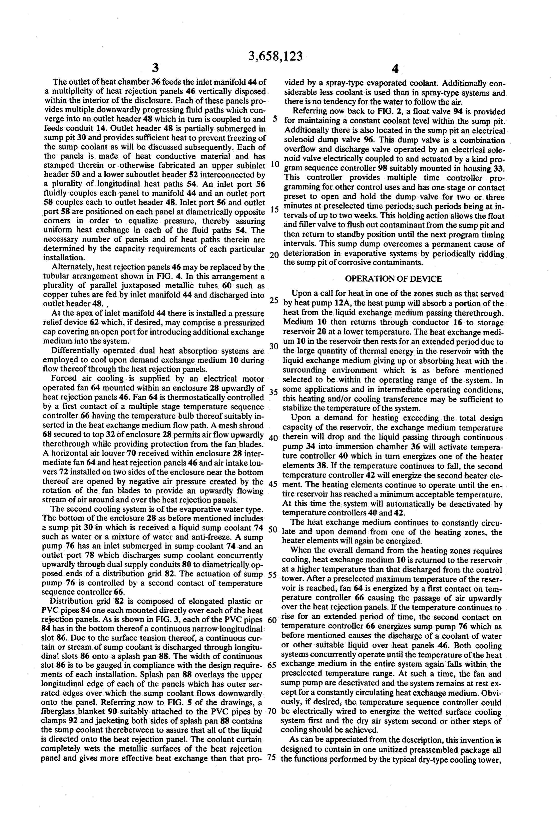
The outlet of heat chamber 36 feeds the inlet manifold 44 of vided by a spray-type evaporated coolant. Additionally con a multiplicity of heat rejection panels 46 vertically disposed siderable less coolant is used than in spray-type systems and within the interior of the disclosure. Each of these panels pro there is no tendency for the water to follow the air. vides multiple downwardly progressing fluid paths which con Referring now back to FIG. 2, a float valve 94 is provided verge into an outlet header 48 which in turn is coupled to and for maintaining a constant coolant level within the sump pit. feeds conduit 14. Outlet header 48 is partially submerged in Additionally there is also located in the sump pit an electrical sump pit 30 and provides sufficient heat to prevent freezing of solenoid dump valve 96. This dump valve is a combination the sump coolant as will be discussed subsequently. Each of overflow and discharge valve operated by an electrical sole the panels is made of heat conductive material and has noid valve electrically coupled to and actuated by a kind pro stamped therein or otherwise fabricated an upper subinlet 10 gram sequence controller 98 suitably mounted in housing 33. header 50 and a lower suboutlet header 52 interconnected by This controller provides multiple time controller pro a plurality of longitudinal heat paths 54. An inlet port 56 gramming for other control uses and has one stage or contact fluidly couples each panel to manifold 44 and an outlet port preset to open and hold the dump valve for two or three 58 couples each to outlet header 48. Inlet port 56 and outlet minutes at preselected time periods; such periods being at in port 58 are positioned on each panel at diametrically opposite 15 tervals of up to two weeks. This holding action allows the float corners in order to equalize pressure, thereby assuring and filler valve to flush out contaminant from the sump pit and uniform heat exchange in each of the fluid paths 54. The then return to standby position until the next program timing necessary number of panels and of heat paths therein are determined by the capacity requirements of each particular 20 deterioration insump intervals. This dump overcomes a permanent cause of evaporative systems by periodically ridding installation.
Alternately, heat rejection panels 46 may be replaced by the the sump pit of corrosive contaminants. tubular arrangement shown in FIG. 4. In this arrangement a OPERATION OF DEVICE plurality of parallel juxtaposed metallic tubes 60 such as copper tubes are fed by inlet manifold 44 and discharged into 25 Upon a call for heat in one of the zones such as that served outlet header 48. by heat pump 12A, the heat pump will absorb a portion of the At the apex of inlet manifold 44 there is installed a pressure heat from the liquid exchange medium passing therethrough. relief device 62 which, if desired, may comprise a pressurized Medium 10 then returns through conductor 16 to storage cap covering an open port for introducing additional exchange reservoir 20 at a lower temperature. The heat exchange medi medium into the system. um 10 in the reservoir then rests for an extended period due to Differentially operated dual heat absorption systems are 30 the large quantity of thermal energy in the reservoir with the employed to cool upon demand exchange medium 10 during liquid exchange medium giving up or absorbing heat with the flow thereof through the heat rejection panels. surrounding environment which is as before mentioned Forced air cooling is supplied by an electrical motor selected to be within the operating range of the system. In operated fan 64 mounted within an enclosure 28 upwardly of 35 some applications and in intermediate operating conditions, heat rejection panels 46. Fan 64 is thermostatically controlled this heating and/or cooling transference may be sufficient to by a first contact of a multiple stage temperature sequence stabilize the temperature of the system. controller 66 having the temperature bulb thereof suitably in Upon a demand for heating exceeding the total design serted in the heat exchange medium flow path. A mesh shroud capacity of the reservoir, the exchange medium temperature 68 secured to top 32 of enclosure 28 permits airflow upwardly 40 therein will drop and the liquid passing through continuous therethrough while providing protection from the fan blades. pump 34 into immersion chamber 36 will activate tempera A horizontal air louver 70 received within enclosure 28 inter mediate fan 64 and heat rejection panels 46 and air intake lou ture controller 40 which in turn energizes one of the heater elements 38. If the temperature continues to fall, the second vers 72 installed on two sides of the enclosure near the bottom temperature controller 42 will energize the second heater ele thereof are opened by negative air pressure created by the 45 ment. The heating elements continue to operate until the en rotation of the fan blades to provide an upwardly flowing tire reservoir has reached a minimum acceptable temperature. stream of air around and over the heat rejection panels. At this time the system will automatically be deactivated by The second cooling system is of the evaporative water type. temperature controllers 40 and 42. The bottom of the enclosure 28 as before mentioned includes a sump pit 30 in which is received a liquid sump coolant 74 50 lateTheandheat exchange medium continues to constantly circu upon demand from one of the heating zones, the such as water or a mixture of water and anti-freeze. A sump heater elements will again be energized. pump 76 has an inlet submerged in sump coolant 74 and an When the overall demand from the heating zones requires outlet port 78 which discharges sump coolant concurrently cooling, heat exchange medium 10 is returned to the reservoir upwardly through dual supply conduits 80 to diametrically op at a higher posed ends of a distribution grid 82. The actuation of sump 55 tower. Aftertemperature than that discharged from the control a preselected maximum temperature of the reser pump 76 is controlled by a second contact of temperature voir is reached, fan 64 is energized by a first contact on tem sequence controller 66. perature controller 66 causing the passage of air upwardly Distribution grid 82 is composed of elongated plastic or over the heat rejection panels. If the temperature continues to PVC pipes 84 one each mounted directly over each of the heat rise for an extended period of time, the second contact on rejection panels. As is shown in FIG. 3, each of the PVC pipes 60 temperature 84 has in the bottom thereof a continuous narrow longitudinal controller 66 energizes sump pump 76 which as slot 86. Due to the surface tension thereof, a continuous cur before mentioned causes the discharge of a coolant of water tain or stream of sump coolant is discharged through longitu or other suitable liquid over heat panels 46. Both cooling dinal slots 86 onto a splash pan 88. The width of continuous systems concurrently operate until the temperature of the heat slot 86 is to be gauged in compliance with the design require 65 exchange medium in the entire system again falls within the ments of each installation. Splash pan 88 overlays the upper preselected temperature range. At such a time, the fan and longitudinal edge of each of the panels which has outer ser sump pump are deactivated and the system remains at rest ex rated edges over, which the sump coolant flows downwardly cept for a constantly circulating heat exchange medium. Obvi onto the panel. Referring now to FIG. 5 of the drawings, a ously, if desired, the temperature sequence controller could fiberglass blanket 90 suitably attached to the PVC pipes by 70 be electrically wired to energize the wetted surface cooling clamps 92 and jacketing both sides of splash pan 88 contains system first and the dry air system second or other steps of the sump coolant therebetween to assure that all of the liquid cooling should be achieved.
is directed onto the heat rejection panel. The coolant curtain As can be appreciated from the description, this invention is completely wets the metallic surfaces of the heat rejection designed to contain in one unitized preassembled package all panel and gives more effective heat exchange than that pro 75 the functions performed by the typical dry-type cooling tower,
Page 7
evaporative cooling tower, liquid immersion heaters, circulat directly above and parallel with the upper end of each ing pumps, forced air passage, sump pumps, and heat rejection of said heat exchange panels; anels. said elongated member having therein a continuous lon p During the detailed description of the preferred embodi gitudinal slot in the underside thereof, ment specific language has been used for the sake of clarity. 5 a pump disposed in said coolant sump in the bottom of However, it is to be understood that the language used is for said enclosure;
the sake of clarity and not by way of limitation. Such language conduit means for fluidly connecting the outlet of said includes all equivalents which operate in a similar manner to coolant pump with each of said elongated members accomplish a similar purpose. whereby coolant within said sump is pumped into each What is claimed: 10 1. In a heating and cooling system for buildings where a heat elongated member and discharged therefrom through said slot in a continuous curtain onto said heat exchange medium is circulated through a plurality of indepen exchange panel.
dently operated reverse cycle heat pumping units, each unit having an inlet and an outlet for said heat exchange medium, member ofapparatus 2. An as in claim 1 wherein said elongated said coolant system is jacketed by a fiberglass blan an apparatus for operatively controlling the temperature of 15 ket which contains said water therebetween. said heat exchange medium within a preselected temperature 3. An apparatus as in claim including a splash pan range comprising:
an outer enclosure having a bottom, a top and side, said bot disposed within said enclosure between and parallel with said elongated member and overlaying upper end of each of said tom being leakproofto form a coolant sump;
at least one heat rejection panel disposed within said disclo 20 rejection
panels.
apparatus as in claim including a heat exchange sures, each of said heat panels having an inlet for receiv medium storage reservoir ing said heat exchange medium from the outlet of said medium circulating path;disposed within said heat exchange said heat exchange reservoir reverse cycle heat pump units and an outlet in fluid com adapted to conserve the thermal energy of said heat exchange munication with the inlet of said reverse cycle heat pump medium.
ing units whereby said heat exchange medium circulates 25 in a closed path between and through said pumping units upwardly 5. An apparatus as in claim 1 including fan means disposed and said heat rejection panels; of said evaporated coolant system and adapted to a continuous operating pump for circulating said heat jection create a flow of air upwardly around said each of said heat re exchange medium in said closed system; panels.
thermostatically controlled heating elements disposed in 30 6. An apparatus as in claim 1 including an electrically sole said closed heat exchange path and adapted to operative noid operated dump valve disposed within said coolant reser ly heat said heat exchange medium; voir and adopted to automatically flush said reservoir at an evaporative cooling system comprising: preselected intervals.
an elongated member disposed within said enclosure k g : 3 x:
Provenance
- Collection
- Cited prior art
- Original PDF
- patentimages.storage.googleapis.com →
- Filed
- 1970-10-19
- Pages
- 7
- Method
- pdftotext (the PDF's own text layer) + pdftoppm 300dpi page scans
- Source
- Google Patents bibliographic record
- Granted
- 1972-04-25
- Inventors
- Donald S Root
- Transcribed from
- patentimages.storage.googleapis.com →