patent · US2636124
Antenna array system
21 April 1953
Page 1
Drawing sheet — no readable text.
Page 2
Patented Apr. 21, 1953
UNITED STATES PATENT OFFICE
ANTENNA ARRAY SYSTEM
Leonard Hatkin, Elberon, N. J., and John Ruze,
Cambridge, Mass., assignors to the United
States of America as represented by the Sec retary of the Army
Application May 1, 1950, Serial No. 159,352
(Granted under Title 35, U. S. Code (1952),
The invention described herein may be manu of the directive lobe is effected either alternately factured and used by or for the Government for with the radar pulsing or at an arbitrarily chosen governmental purposes, without the payment of rate so that echo signal obtained from a reflect any royalty thereon. ing object with the two different directivities This invention relates to linear antenna, ar may be compared. Echoes which are of equal rays and in particular to linear arrays of the amplitude when received with both directivities type employed in radar systems. Particularly are then known to originate from an object pre this invention relates to a circuit for supplying cisely located on a line where the amplitude of to the antenna, elements of an array wave energy the overlapping directive lobes are equal. This of chosen amplitude and phase in a manner to 10 type of operation is known as lobe Switching. facilitate lobe Switching. In prior art arrangements the elements of Antenna, arrays of the type under considera the array are fed from transmission lines of tion are described in nearly all radio text books, chosen lengths and chosen characteristic im for example, in Terman's "Radio Engineers' pedances in order to Supply the currents of requi Handbook,' McGraw-Hill Book Co. 1943, pages 5 site phase and amplitude to the Several elements. 823-824. Lobe Switching of such arrays is also For the lobe switching operation the currents are disclosed in many places in recent literature par fed asymmetrically to the array to provide the ticularly in the volume, “Principles of Radar’ conjugate phase required. The asymmetrical prepared by the Staff of M. I. T. Radar School, feed point is shifted in accordance With the lobe chapter 4. Therefore only such description of 20 switching and in this operation the entire power the characteristics of an array necessary to the to the array must be Switched. In these ar illustration of the present invention will be given rangements it has been difficult to design the here. feed circuits to provide proper amplitude and The linear array is composed of a plurality phase to each element in a circuit So Organized of pairs of conjugate antenna elements symmet that the lobe Switching operation may be ac rically Spaced along an axis relative to a center complished. It has therefore been the practice location, which may, in the case of an odd num to arbitrarily space the array elements a half ber of elements, be the location of a center ele wave length apart to simplify the phasing prob ment. The currents fed to elements of the con lem and to ignore the tapering of currents to jugate pairs are of equal amplitude and of con 30 the elements and instead supply currents of equal jugate phase. The term “conjugate phase,' as amplitude to each element. here employed, means that the sign of the phase It is accordingly an object of the present inven angle of the currents is opposite in elements of tion to provide an improved antenna, array ar a pair. rangement which avoids one or more of the dis Ordinarily a uniform spacing between elements 35 advantages and limitations of the prior art ar is employed which is of the Order of a half wave rangements and which has improved operating length. So that a single major directive lobe is features.
produced. A lobe of maximum directivity is ob A further object of this invention is to provide tained when the currents in the elements are in a linear antenna array an improved arrange equal but it is well known that tapering the cur 40 ment for Supplying Wave energy of a chosen fre rents So that the elements spaced further from quency in predetermined amplitude and in con the center location receive less current results in jugate phase relation to conjugate pairs of an a desirable reduction of the amplitude of minor tenna elements.
lobes, although the Width of the major lobe is It is a further object of the present invention increased to Some extent. 45 to provide in a linear antenna, array an im If the currents to the Several elements are all proved arrangement for radar lobe switching of like phase, the directive pattern is normal to which involves switching only a portion of the the axis of the array. However, by proper choice energy Supplied to the array. of the conjugate phasing of the elements the Also, in accordance with the present invention, directive lobe will be tilted by a chosen angle 50 in a lobe SWitching linear antenna, array having from normal. If the conjugate phasing is re Conjugate pairs of antenna elements symmet versed for each pair of elements the lobe is tilted rically Spaced relative to a center position, there by the same angle in a conjugate direction, that is provided a System for supplying to the ele is, it will be shifted from, say, plus 5 of normal ments of each conjugate pair, energy of a chosen to minuS 5. In many radar Systems a shifting frequency in predetermined amplitude and in
Page 3
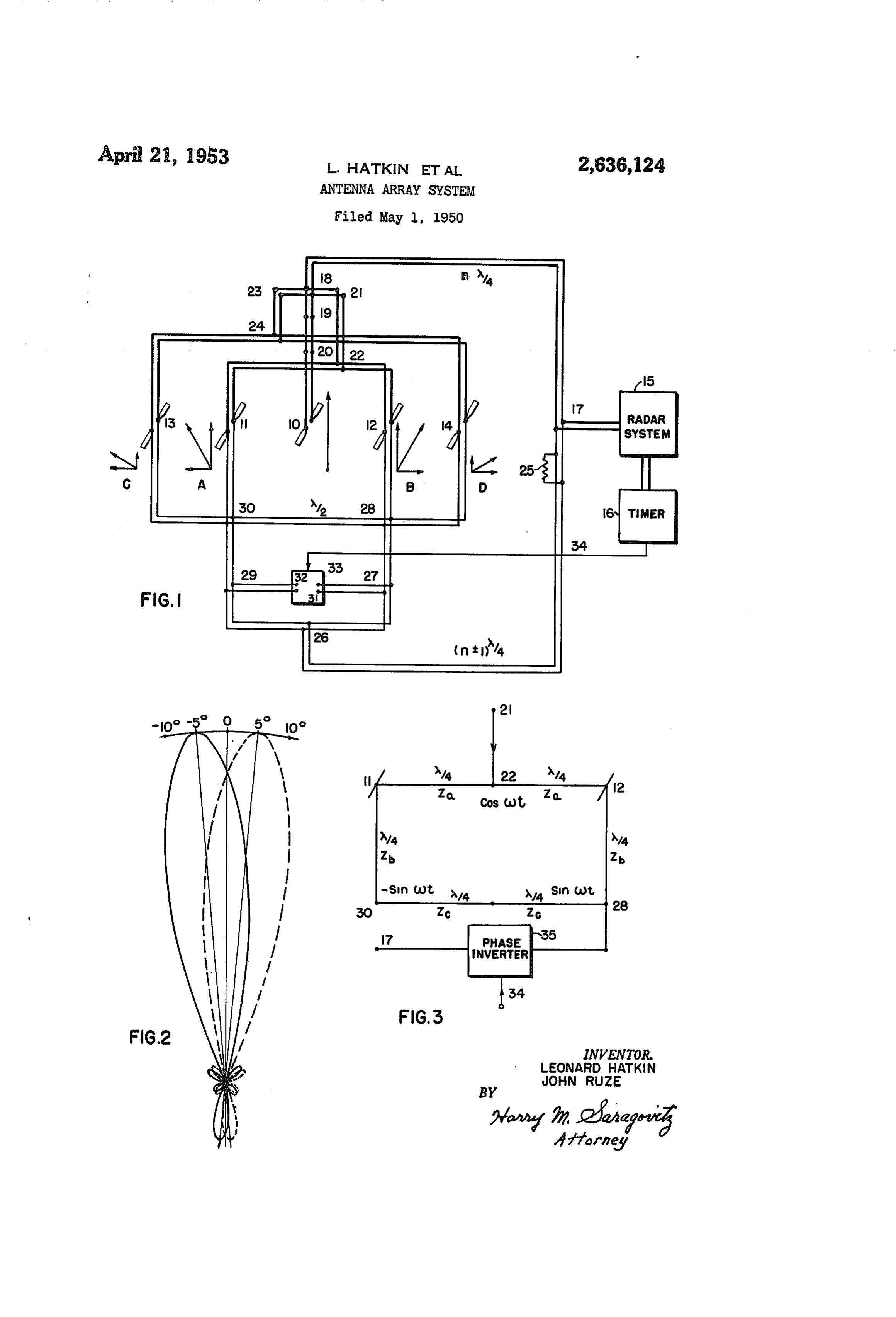
conjugate phase relation. The energy Supplied supplies wave energy to element O. From junc to each element is resolvable into a component tion 8 for the conjugate pair f, 2 the length of reference phase and a component of quadra of the transmission line is also comprised of ture phase. The system comprises, for each pair, three quarter wave length sections. These are passive circuit means, such as a hybrid ring cir the quarter wave length sections 8-2, 21-22 cuit for independently supplying the components and the branching pair 22-f and 22-2. In of reference phase to the elements of each pair similar manner it will be noted that the length and the components of quadrature phase in of transmission line from the junction point 8 anti-phase relation to the elements of each pair. to the conjugate pair of elements f3, 4 is also via Further means are provided for periodically re 10 three quarter wave length sections, to Wit, 8-23, versing the anti-phase relation in Order COr 23-24, 24-4 and 24-3.
respondingly to reverse the conjugate phase re It will be clear that the electrical length from lation. the junction point via the upper path described For a better understanding of the present in is the same number of Wave lengths to each of vention, together with other and further ob the five antenna, elements and therefore the cur jects thereof, reference is had to the following rents Supplied to each of these Will be in time description taken in connection with the ac phase. These in-phase currents will be referred companying drawings and its scope will be to as of reference phase and the arrangement pointed out in the appended claims. - -- accordingly constitutes means for supplying In the drawings, Fig. 1 is a diagram partly in 20 Wave energy components of reference phase to block and partly schematic illustrating a lobe the elements of the array. To indicate this switching antenna, array in accordance with a clearly small vector diagrams have been placed preferred form of the invention; Fig. 2 is a polar adjacent to each of the elements and it will be diagram illustrating the directivity character noted that a vertical component of current is in istics of the array shown in Fig. 1; and Fig. 3 25 dicated as being supplied by the upper or in is in part a simplified diagram illustrating the phase netWork to each element of the array. operation of an essential part of the circuit of Consider now the lower part of the circuit Fig. 1 and including in block diagram an al from the junction f, which is termed the anti ternative arrangement for accomplishing the phase network and which constitutes means for lobe Switching operation. 30 supplying the components of quadrature phase Referring now to Fig. 1 of the drawings, the in anti-phase relation to the antenna, elements of elements of a linear antenna, array are shown each conjugate pair. It Will be noted that the as a central dipole antenna, element i), a first electrical length as labeled on the drawing from conjugate pair of dipoles and 2, and a Sec point 7 to point 26 is also an integral number ond conjugate pair of dipoles 3 and 4 Sym of quarter Wave lengths but differs by a quarter metrically spaced from the center position Oc Wave length from the principal transmission line cupied by element O. A complete radar unit for fi-8, of the upper or in-phase network. From transmitting and receiving pulses of radio fre junction point 26 connection is made to elements quency energy is indicated by the block unit 5. f2 and 4 via the quarter wave length sections Coupled to 15 is a timer unit f6 which controls 40 26-27, 27-28 and the branching pair 28- 2 and the pulsing operation of 5. 28-14. In similar manner the elements 1-3 In a pulsing radar system as is well known, are connected to point 26 by the quarter wave pulses of radio frequency energy are transmitted length sections 26-29, 29-30 and the branching at a chosen repetition rate and during the in pair 30- and 30-3. Between junctions 28 tervals between pulses echoes from reflecting ob 45 and 30 there is a transmission line section of a half wave length.
jects are received. It is well known that antenna, systems of the type here under consideration In the anti-phase network, there is also pro operate with the same directivity in the receiv to vided a lobe switching unit of conventional type ing operation as in the transmission. Such which the quarter wave length sections 27-3 reciprocal operation is ordinarily referred to as 50 and 29-32 are coupled. Operation of the lobe operation in accordance with the reciprocity switching unit is accomplished in synchronism theorem. Accordingly, the description of the With the pulsing of the radar by control means system will here be confined entirely to opera indicated by the connection labeled 34 between tion of the System as a transmitter and it will timer 6 and the lobe switching unit 33. How be understood in both the description and in the 55 ever the lobe SWitching need not be synchronous appended claims that the reciprocity theorem With the radar pulsing and may be accomplished holds true for the case of reception. on an arbitrarily chosen rate. Shunting the Considering then the circuit arrangement, line T-26 is a stabilizing resistor 25 the func from the transmitting point of view only, the tion of which Will be later described. radar transmitter 5 is coupled to the array ele 60 The exact structure of lobe Switch unit 33 is ments via two channels by means of the two not illustrated since it may be of any conventional transmission lines which join at point T. Fol known form Such as that shown in Fig. 40, page lowing the upper part of the diagram the trans 9-64 of the volume “Principles of Radar' re mission line from point to the point f8 is, as ferred to above. For one operational position of labeled on the drawing, of an integral number, 65 the lobe switching unit 33 the current supplied m, of quarter wave lengths. It will be noted that to the antenna elements 2 and it are indicated the points where the lengths of line connect are as horizontal current components in the vector indicated by pairs of dots and it Will be under diagrams B and D. For the antenna, elements stood that the length of transmission line, co and 3 similar anti-phased horizontal current axial cable or whatever may be used is a quarter 70 components are indicated in the vector diagrams of a wave length between pairs of dots unless it A and C.
is otherwise specifically labeled on the drawing. Considering now the operation of the system, Thus, from the junction point f8 three quarter the radar transmitter supplies wave energy of a wave length sections, that is, sections 8-9, chosen frequency and magnitude via the con 19-20 and 20-10 are shown in the line which 75 nection shown from unit 5 to the junction point
Page 4
il. At point 7 the energy is divided between phase to elements and 3 because of the fact the upper in-phase circuit network and the that the path 28-30 is a half wave length and lower anti-phase network. At junction 8 the therefore causes the anti-phasing or change of Current is divided between three paths, one path 180 in the currents supplied to these elements. being sections 8-9, 9-20 and 20 to element It will also be noted that the path 7-26 is 0 where current of the magnitude indicated by labeled (n-1) X/4 to indicate its length is an the vertical vector is supplied. Current from integral number of quarter wave lengths but dif junction 8 is Supplied via quarter wave Sec fering by one quarter wavelength from the length tions 8-2 and 2-22 where it is divided and of path - 8 of the in-phase network. It will supplied in equal amplitude and in like reference 10 be clear, therefore, that the currents supplied to phase to elements and 2 as indicated by the the several antenna, elements via the anti-phase vertical vectors of the diagrams A and B. The network are in quadrature phase relation to amount of current fed to these elements is de those currents Supplied in reference phase by the termined by the characteristic impedance of the in-phase network. The quadrature currents are transmission line Sections and the values of char 5 therefore as indicated by the horizontal vectors acteristic impedance to be chosen can be de in the vector diagrams A, B, C and D. The re termined for each section by calculation employ Sultant conjugate currents are indicated by the ing transmission line equations. The antenna Sum vectors in these vector diagrams. elements of the array are here assumed to be of If now the lobe switching unit 33 operates to similar characteristic impedance and the value 20 Short circuit the quarter wave section 32-29 at of the current supplied to the elements is de point 32 and to open line 3-27 at point 3 ?, then termined and the arrangement is Such as to it will be clear that in effect the path 26, 27, 28 match the lines to the characteristic impedance has been removed from the circuit and the path of the elements by designing the sections f&-2, 26, 29, 30 has been placed in operation. Under 2-22 and from 22 to the elements and 2 25 these conditions the quadrature components of as quarter Wave matching Sections, i. e., quarter Current shown in vector diagrams A and C will wave transformers. It will be noted that here be reversed since the length of the path to ele there is no problem of relative phasing since all ments and 3 has been decreased by a half line sections are of a quarter Wave length and Wave length. Conversely the length of path to the length of path from junction 7 to the an 30 elementS 2 and 4 is increased a half wave tenna elements is the same so that the current length by the section 30-28 and the quadrature components supplied to the conjugate pair will currents in the diagrams B and D will also be be of the same phase as the current Supplied to reversed. In other words, the currents supplied by the in-phase network are left fixed in the lobe element 0, that is, they will be of reference phase.
In similar manner from junction 8 via the quar 35 Switching operation while the quadrature cur ter wave length sections 8-23, 23-24 and the rents Supplied by the anti-phase network are re quarter wave sections leading to elements 3 and versed with each operation of lobe SWitch 33 A 4 currents of suitable amplitude and of ref effectively to reverse the conjugate phasing of erence phase are supplied thereto. It may be currents supplied to the conjugate pairs of an noted here and it will be explained more fully 40 tenna, elements. It will be clear therefore that later that the currents supplied by the in-phase the lobe switching operation is effected by switch network and those supplied by the anti-phase ing only a portion of the energy supplied to the network are considered to energize the antenna array.
elements independently of each other. Fig. 2 shows a polar diagram of the directivity Considering now the anti-phase network, the 45 pattern of the array of Fig. 1 for an actual struc feed line from junction point 7 to point 26 is ture where the currents supplied to the elements chosen of suitable characteristic impedance to are proportioned as follows:
Reference current------------ 3 4.16 3 1. Quadrature number--------- i.49 1.49 0. jF.49 iF1.49 Normalized Conjugate Cur rent----------------------- 1.0156° 1.851-26 2.3 1851–F26° 1.0/-F56° provide in this branch the desired amount of the 55 The conjugate currents are each the vector total current, taking into consideration the por sum of the reference current and the quadrature tion of current dissipated in the shunt resistor 25 current. In the row labeled normalized conju So that suitable amplitude is supplied at junction gate current the values have been divided by a 26. The lobe Switching circuit as before men factor to make the currents in the end elements tioned is of a conventional type known in the art 60 unity SO that the amount of tapering can more and its operation may be described as follows. easily be visualized.
ASSume a time in the operation when the lobe The diagram shows the directivity in a hori switching unit 33 effectively short circuits the zontal plane for dipole elements oriented to pro terminal Si of quarter wave section 3-27 and vide a vertically polarized wave, The pattern is leaves the terminal 32 of quarter wave section 65 unidirectional because the array elements are 32-29 open. The effect is then to disconnect the mounted approximately a quarter wave length in section 3-2 at junction 27 and to short circuit front of a non-resonant reflecting screen. The the section 32-29 at the junction point 29. spacing of the elements is 0.625 wave length and Under these conditions the path 26, 29, 30 may be Screen Separators were located between the dipole considered as having been completely removed 70 elements to reduce mutual coupling between from the circuit and that all energy is supplied them. The antenna elements instead of being via the path 26, 27, 28. It will be clear then that directly connected to the line sections as shown current from the junction 28 is Supplied in equal in Fig. 1, are connected each via a half Wave amplitude and like phase to elements 2 and f4 length of transmission line since the insertion of and likewise in equal amplitude but in anti 75 low loss line Sections of a multiple of a half wave
Page 5
length leading to the antenna, elements does not references will be found to hybrid junctions and alter the described operation. The in-phase and hybrid T's. For example, the hybrid T and its anti-phase networks may therefore be construct relation to the earlier form of hybrid transformer ed as units separated from the actual array. is explained at pages 7-11 to 7-13 in the Radio For one position of the lobe switching the Engineers' Handbook-Henney, 4th edition, Mic major lobe is in a direction of +5° from the di Graw-Hill & Company, 1950. Examples of rection normal to the axis of the array as shown hybrid junction circuits will also be found at by dotted lines. For the other lobe Switching page 353 of Reference Data for Radio Engineers, position the major lobe has a direction of -5 3rd edition, 1949, published by Federal Tele from the normal as shown by solid line. It will 0 phone & Radio Corporation. The term hybrid be noted in this diagram that the minor lobes are circuit as here employed is intended to designate materially reduced in magnitude. a duplex balancer circuit which may be of either Thus far it has been assumed that the in the Wave guide junction type or the transformer phase and the anti-phase networks operate inde circuit type.
pendently to feed wave energy to the antenna 5 Referring back to Fig. 1, it will be clear that elements without interaction one upon the other. the in-phase and anti-phase branches which It will now be explained, with the aid of the dia supply currents to the other conjugate pair of gram, Fig. 3, why the two networks operate inde elements 3 and 4 also comprise a hybrid ring pendently. Thus in Fig. 3 the part of the dia such as described in Fig. 3 and that the path gram including elements and 2 is shown in 20 of a half wave length, 28-3), is common to both simplified form and it will be noted that the the hybrid ring Supplying elements and 2 circuit-connecting points. 22, , 30, 28, 2 and and the ring supplying elements 3 and 4. The - back to 22 is a closed circuit or ring the total hybrid circuit is therefore a passive circuit net electricallength of the ring being one and a half Work which independently Supplies current Com wave lengths. The in-phase or reference phase 25 ponents of reference phase to the antenna ele feed connecting at junction 22 and indicated by ments of a conjugate pair and Simultaneously the notation Cos wit, is a quarter Wave length supplies the components of quadrature phase in from both elements if and 2 to Supply in-phase anti-phase relation to the elements of the pair. currents to these elements. If we consider the Also the lobe switching network of Fig. 1 when current as also travelling:to, say, element if Via 30 it is actuated under control of timer 6 via the path 22, 2, 28, 30, i, it will be noted that the connection 34 or by other means, comprises this distance is one and a quarter wave lengths a means for periodically reversing the anti-phase so that current travelling via this path from 22 relation correspondingly to reverse the Conjugate will also arrive at element i in-phase. Sini phase relation of the currents Supplied to a larly currents from junction 22 may reach ele 35 conjugate pair of elements.
ment 2 by either path around the ring and The Operation as illustrated and described for arrive in time-phase. However, it will be noted Fig. 1 of the lobe SWitching arrangement ef that currents entering at junction 22 and travel fectively operates alternately to connect the ling both ways will arrive at point 28 and also anti-phase network at points 28 and 3 but it at point 30 in opposite phase. Therefore no 40 will be evident that alternative arrangements energy from point 28 can leave the circuit as the are possible. Thus in Fig. 3 a phase inverter voltage there is zero. Point 28 is therefore a is indicated in block diagram as unit 35 to which balance point and similarly point 30 is a balance the quadrature currents from junction are point. Supplied and the output of the phase inverter Considering the energy of quadrature phase 45 35 is connected only to junction point 28. The supplied to the network: at point 28 and indicated phase inverter 35 is assumed to be a device of by the notation Sin 20t, this energy can reach any well known type which may operate as a element 2 directly by the quarter wave length switch to reverse the polarity of Wave energy path from 28 or via the path thru points 28, 30, supplied to its input. For example a polarity , .2in both of which cases the energy arrives -50 inverting electron tube Stage or any arrange at 2 in time phase. However, the energy from ment which Will Operate to SWitch a half wave point 28 will reach element in anti-phase to length section of line into the path might be the energy reaching element 2; that is, it will so employed. Thus for One condition of opera arrive in phase at by both paths around the tion of phase inverter 35 the quadrature currents ring but will be 180° out of phase with energy 55 are Supplied at terminal 28 exactly as was pre arriving at element f2. The anti-phasing is in viously described. However when, under control dicated by the notation -Sin Ut at point 30. of the connection 34 the phase inverter 35 op However, at point 22, it will be noted, that energy erates to reverse the polarity of current Sup entering at point 28 will reach 22 in opposite plied to junction 28, it will be clear that the phase over the two paths and therefore point 22 60 quadrature components are all reversed in po is a balance point so that no energy supplied to larity (phase) to provide exactly the same the circuit at point 28 (and similarly at point 30) result as obtained when the connection was can leave the circuit...at point 22. Switched from point 28 to point 30. The phase The arrangement thus far described is termed inverter 35 therefore operates periodically to a hybrid circuit and the particular form is a 65 reverse the anti-phase relation of the quadrature hybrid ring circuit of the type described in U. Currents Supplied to the antenna, elements of S. Patent No. 2,445,895 issued July 27, 1948 in conjugate pairs correspondingly to reverse the the name of W. A. Tyrrell. For many years, conjugate phase relation of the resultant cur hybrid circuits have been-employed for balancing rentS Supplied to the pairs. in telephone repeater systems where the circuit 70 Because of the balanced relations, above-de takes the form of the Well known hybrid coil Scribed for the Fig. 3 ring circuit, the in-phase or transformer and from this art the term hybridpart of the circuit can be considered completely originates. The term has been carried over into independent of the anti-phase part of the cir the ultra high frequency or microWave radio cuit. Thus the sections 22-f and 22-2 may and radar art and throughout the literature 75. be designed as quarter wave matching sections
Page 6
of impedance 2a (as labeled) to match the line an even number of quarter wave lengths Equation 21-22 to elements and 2 and provide equal 1 becomes in-phase currents thereto.
Similarly the Sections 28-2 and 30-ft may (3) be designed as quarter wave matching Sections of impedance 2 (as labeled) independently to Which shows that the currents fed to the ele match the line 2-28 to elements and 2 ments depend directly on their impedance. To and provide equal quadrature phase currents obviate this difficulty the resistor 25 is placed in thereto. The half-wave length section 28-3 shunt With the anti-phase line at a quarter wave may have any other arbitrarily chosen char O length distance from the point . If this re acteristic impedance Zic (as labeled) without af sistor is Small compared with the line impedance, fecting the operation since the purpose of this the Voltage at its terminals Will be stabilized so section is to anti-phase the quadrature currents that the distance from 25, now considered as the Supplied to the elementS and the properties as Source, to each antenna, element via the anti a half wave section are such as to provide anti 5 phase network is also an odd number of quarter phasing independently of the characteristic in Wave lengths and the currents supplied by this pedance. network will also be independent of the in Referring again to Fig. 1, it was pointed out pedance of the elements. It will be evident that that lines - and I-26 differ in electrical power is lost in resistor 25, but its contribution length by a quarter wave length to provide the 20 in making the operation independent of in quadrature relation between currents Supplied pedance variations of the antenna, elements war by the in-phase and anti-phase networks. If rants its use. Theoretically, it can be shown now we make in an even integer so that line that, with passive circuit elements, quadrature 7-8 is an even number of wave lengths it currents can only be obtained by employing a Will be seen that the electrical length to the loSSynetwork and the use of a stabilizing resistor, array elements is an odd number at quarter Such as resistor 25, is a requisite to stable Op Wave lengths for the in-phase network and an eration.
even number of quarter Wave lengths for the While there have been described What are at anti-phase network. For the in-phase network present considered to be the preferred embodi advantage can now be taken of a known theorem 30 ments of this invention, it Will be obvious to those in transmission lines, namely that the currents skilled in the art that various changes and modi Supplied from a source to a load via a line of fications may be made therein. Without depart an odd number of quarter Wave lengths will be ing from the invention, and it is, therefore, aimed independent of the impedance of the load. Con in the appended claims to cover all such changes sider the well known formula for a lossless trans 35 and modifications as fall Within the true Spirit mission line and Scope of the invention.
What is claimed is:
In-z OS 0- i2 sin 6 (1) 1. In a linear antenna, array having a conju where gate pair of antenna, elements symmetrically 40 spaced relative to a center position, a System for
IR is the load current supplying to the elements of said pair energy of Eo is the input voltage a chosen frequency in predetermined annplitude ZR and Z1 are the load impedance and line in and in conjugate phase relation, the energy Sup pedance respectively and plied to each element being resolvable into a com G is the length of the line in radians 45 ponent of reference phase and a component of When the line is of a quarter wave length quadrature phase, Said System comprising a (or an odd multiple thereof) the expression source of wave energy, an in-phase circuit Sup becomes plying a portion of said energy in reference phase to each of said elements, the circuit path fron
I= - Eo Z, (2) 50 said source to each element being an Odd nun ber of quarter wave lengths, an anti-phase Cir showing that, if the input voltage is held con cuit, Supplying a portion of Said energy in Gllad Stant, the load current is independent of the rature phase to each of Said elementS, the cir in pedance ZR of the load. cuit path from said source to each element be It follows, therefore, that if, for the in-phase ing an even number of quarter wave lengths, ell network, the lengths of line from to the ergy dissipative means shunting Said anti-phase Several antenna elements are of an odd number circuit path at an odd number of quarter Wave of quarter wave lengths then the currents to lengths from each of said elements, said circuits the elements will be unaffected by the impedance together comprising, a hybrid ring balancing cir of the elements. This becomes important When 60 cuit for independently supplying the components Operation is changed from the nominal operating of reference phase to the elements of said pair frequency to some other frequency. The nominal and the components of quadrature phase in anti operating frequency is that for which the lengths phase relation to the elements of said pair. of line sections are exact quarter or half Wave 2. In a linear antenna, array having a plurality Sections and Operation at the nominal operating 65 of conjugate pairs of antenna, elements symmet frequency was a SSurned in the previous descrip rically spaced relative to a center position, a SyS tions. When the operation is at some moderately tem for supplying to the elements of each Con different frequency the departure of the sections jugate pair energy of a chosen frequency in pre from exact quarter or half wave length is not determined amplitude and in conjugate phase material but the change in impedance of the relation, the energy supplied to each element be antenna, elements may be material. Therefore ing resolvable into a component of reference making the currents fed to the elements in phase and a component of quadrature phase, Said dependent of their impedances is advantageous. system comprising a plurality of hybrid ring cir However for the anti-phase network where the cuits, one for each pair, for independently Sup electrical lengths from point it to each element is 75 plying the components of reference phase to the
Page 7
elements of the pair and the components of:cquad 7. In a lobe switching linear antenna, array rature phase in anti-phase relation to the ele having conjugate pairs of antenna elementS. Syn ments of the pair, said plurality of hybrid ring metrically spaced relative to a center position, circuits having a common path of a half wave a system for supplying to the elements of each length. 5 conjugate pair energy of a chosen frequency in 3. In a lobe SWitching linear antenna, array predetermined amplitude and in conjugate having a conjugate pair of antenna, elements phase relation, the energy supplied to each ele symmetrically spaced relative to a center posi ment being resolvable into a component of ref-. tion, a system for supplying to the elements of erence phase and a component of quadrature said conjugate pair energy of a chosenfrequency. O phase, said System comprising a Source of Wave in predetermined amplitude, and in conjugate energy, an in-phase circuit supplying a portion phase relation, the energy supplied to each ele- . of said energy in reference phase to each of Said ment being resolvable into a component of ref elements, the circuit path, to each element being erence phase and a component of quadrature an Odd number of quarter wave lengths, an anti phase, said system comprising passive circuit phase circuit supplying a portion of said energy means for independently supplying the COm in quadrature phase to each of Said elements, ponents of reference phase to the elements of the circuit path to each element being an even the pair and the components of quadrature-phase. number of quarter wave lengths, energy dissi in anti-phase relation to the elements of the pative means shunting said anti-phase circuit pair, and means for periodically reversing said. 20 at an odd number of quarter wave lengths from anti-phase relation correspondingly, to reverse each of said elements, said circuits together said conjugate phase relation. Comprising for each pair paSSive circuit means 4. In a lobe Switching linear antenna, array for independently supplying the components of having a conjugate pair of antenna, elements reference phase to the elements of each pair and Symmetrically spaced. relative to a center posi 25 the components of quadrature phase in anti tion, a system for supplying to the elements of phase relation to the elements of each pair, and Said conjugate pair energy of a chosen frequency means for periodically reversing said anti-phase in predetermined amplitude and in conjugate Irelation correspondingly to reverse said conju phase relation, the energy, supplied to each ele gate phase relation.
inent being resolvable into a component of ref 8. In a linear antenna, array having a con erence phase and a component of quadrature jugate pair of antenna, elements, symmetrically phase, said system comprising a hybrid circuit Spaced relative to a center position, a system for means for independently supplying the con Supplying to the elements of said pair energy ponents of reference phase to the elementS. of of a chosen frequency in predetermined ampli the pair and the components of quadrature phase tude and in conjugate phase relation, the energy in anti-phase relation to the elements of the pair, Supplied to each element being resolvable into and means for periodically reversing said anti a component of reference phase and a com phase relation correspondingly to reverse said ponent of quadrature phase, said system compris conjugate phase relation. ing a source of wave energy, an in-phase cir 5. In a lobe Switching linear antenna, array cuit supplying a portion of Said energy in ref having a plurality of conjugate pairs of antenna. erence phase to each of Said elements, the cir elements symmetrically spaced relative to a cen cuit path from said Source to each element be ter position, a system for supplying to the ele ing an even number of quarter wave lengths, an ments of each conjugate pair energy of a chosen anti-phase circuit Supplying a portion of Said frequency in predetermined amplitude and in 45 energy in duadrature phase to each of said ele conjugate phase relation, the energy Supplied to ments, the circuit path from said source to each each element being resolvable into a component element being an odd number of quarter wave of reference phase and a component of quad lengths, energy dissipative means shunting said rature phase, said system comprising for each in-phase circuit path at an odd number of quar pair, hybrid circuit means for independently Sup ter wave lengths from each of said elements, plying the components of reference phase to the Said circuits together comprising a hybrid ring elements of the-pair and the components of quad balancing circuit for independently supplying the rature phase in anti-phase relation to the ele components of reference phase to the elements ments of the pair, and means for periodically re of said pair and the components of quadrature versing said anti-phase relation correspondingly phase in anti-phase relation to the elements of to reverse said conjugate phase relation. Said pair.
6. In a lobe switching linear antenna, array 9. In a linear antenna, array having a conju having a conjugate pair of antenna, elements gate pair of antenna; elements symmetrically symmetrically spaced relative to a center posi spaced relative to a center position, a System for tion, a system for supplying to the elements of 60 Supplying to the elements of said pair energy of said pair energy of a chosen frequency in pre a chosen frequency in predetermined amplitude determined amplitude and in conjugate phase and in conjugate phase relation, the energy Sup relation, the energy supplied to each element be-, plied to each element being resolvable into a ing resolvable into a component of reference component of reference phase and a component phase and a component of quadrature phase, 65 of quadrature phase, said system comprising a said system comprising a hybrid ring circuit hav source of Wave energy, an in-phase circuit. Supr ing three balanced input positions, and a pair of plying a portion of said energy in reference phase output positions symmetrically located relative to each of said elements, the circuit path from to a one of said input positions, means connect said source to each element being 12 quarter Wave ing said elements each to an output: position, 70 lengths where n is an integer; an anti-phase means for supplying the components of refer circuit supplying a portion of said energy in ence phase at said one input position and Switch quadrature phase to each of said elements, the ing means for alternately supplying, the Con circuit path from said source to each element ponents of quadrature phase at the two other being nit-1 quarter wave lengths; energy dissi input positions. 75 pative means shunting the one of said circuit
Page 8
paths which is of an even number of quarter References Cited in the file of this patent wave lengths at an odd number of quarter wave UNITED STATES PATENTS lengths cuits from comprising together each of said elements, a hybrid said cirring balancing NEnber Name Date circuit for independently supplying the compo. 5 28:9 Cork, et al.-------- Jan. 16, 1940 nents of reference phase to the elements of said 2286,839 Schelkunoff ------ June 16, 1942 pair and the components of quadrature phase 3: Hilblad a - a -- - a ty 3. I anti-phase relation to the elements of Said 241034 Gluyas ------------ Nov. 12, 1946 LEONARD HATKN. O 2,415,932 Brown - - - - - - - - - - Feb. 18, 194 OEN RUZE. 2,445,895 Tyrrell ------------ July 27, 1948

Provenance
- Collection
- Cited prior art
- Original PDF
- patentimages.storage.googleapis.com →
- Filed
- 1950-05-01
- Pages
- 8
- Method
- pdftotext (the PDF's own text layer) + pdftoppm 300dpi page scans
- Source
- Google Patents bibliographic record
- Granted
- 1953-04-21
- Inventors
- Hatkin Leonard; Ruze John
- Transcribed from
- patentimages.storage.googleapis.com →