patent · US4820395
Cell for continuous electrolytic deposition treatment of bars and the like
11 April 1989
Page 1 — bibliographic record
United States Patent (19) 11) Patent Number: 4,820,395 Angelini (45) Date of Patent: Apr. 11, 1989 54 CELL FOR CONTINUOUSELECTROLYTIC Attorney, Agent, or Firm-Herbert Dubno; Ronald DEPOSITION TREATMENT OF BARS AND Lianides
THE LIKE
76 Inventor: Sergio Angelini, Residenza del The cell for continuous electrolytic deposition treat Cantone 61, Segrate (Milan), Italy ment of bars or the like according to the invention com 21 Appl. No.: 96,054 prises a closed vessel containing at least one tubular 22 Filed: Sep. 11, 1987 anode through which a bar for electrolytic processing can be conveyed in the axial direction, the bar being 30) Foreign Application Priority Data inserted into the vessel and leaving the vessel through Sep. 12, 1986 IIT Italy ............................... 2686 A/86 respective inlet and outlet mouthpieces equipped with 511 Int. C. ........... a a a as a w C25D 17/00 sealing means, means being present for supplying a flow of electrolytic bath to the anode or anodes and transfer 52 U.S. Cl. ............... - - - - - - - - - - - - - - - - - - - - 204/207
58) Field of Search ......................................... 204/207 ring the bath from the anode to the vessel, producing a flow of the bath inside the anode and parallel to the bar (56) References Cited to be processed, dielectric spacing means also being
3,751,344 8/1973 Angelini.............................. 204/2O7 the adjacent anode and adapted to define a zone of 3,852,170 12/1974 Angelini.............................. 204/207 controlled chemical attack before electroplating begins. Primary Examiner-T. M. Tufariello 12 Claims, 7 Drawing Sheets
Page 2
Drawing sheet — no readable text.
Page 3
Drawing sheet — no readable text.
Page 4
Drawing sheet — no readable text.
Page 5
Drawing sheet — no readable text.
Page 6
Drawing sheet — no readable text.
Page 7
Drawing sheet — no readable text.
Page 8
Drawing sheet — no readable text.
Page 9
ing cell where the electrochemical potentials enable
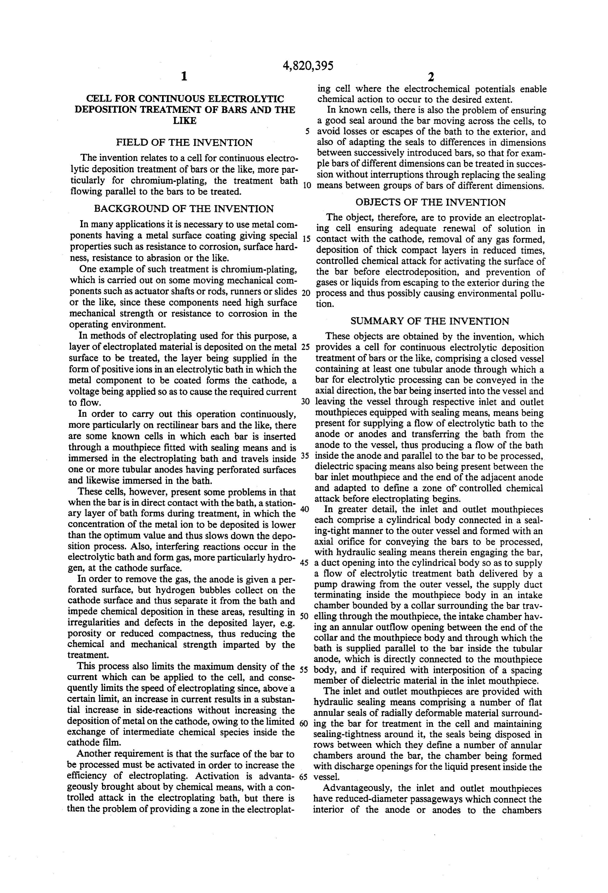
CELL FOR CONTINUOUSELECTROLYTIC chemical action to occur to the desired extent. DEPOSITION TREATMENT OF BARS AND THE In known cells, there is also the problem of ensuring LIKE a good seal around the bar moving across the cells, to avoid losses or escapes of the bath to the exterior, and
FIELD OF THE INVENTION also of adapting the seals to differences in dimensions The invention relates to a cell for continuous electro between successively introduced bars, so that for exam lytic deposition treatment of bars or the like, more par ple bars of different dimensions can be treated in succes ticularly for chromium-plating, the treatment bath 10 meanswithout sion between interruptions through replacing the sealing groups of bars of different dimensions.
flowing parallel to the bars to be treated.
OBJECTS OF THE INVENTION
BACKGROUND OF THE INVENTION
In many applications it is necessary to use metal com ingThecellobject, therefore, are to provide an electroplat ensuring adequate renewal of solution in ponents having a metal surface coating giving special 15 contact with the cathode, removal of any gas formed, properties such as resistance to corrosion, surface hard deposition of thick compact layers in reduced times, ness, resistance to abrasion or the like. controlled chemical attack for activating the surface of One example of such treatment is chromium-plating, the bar before electrodeposition, and prevention of which is carried out on some moving mechanical com gases or liquids from escaping to the exterior during the ponents such as actuator shafts or rods, runners or slides 20 process and thus possibly causing environmental pollu or the like, since these components need high surface t1On.
mechanical strength or resistance to corrosion in the SUMMARY OF THE INVENTION operating environment.
In methods of electroplating used for this purpose, a These objects are obtained by the invention, which layer of electroplated material is deposited on the metal 25 provides a cell for continuous electrolytic deposition surface to be treated, the layer being supplied in the treatment of bars or the like, comprising a closed vessel form of positive ions in an electrolytic bath in which the containing at least one tubular anode through which a metal component to be coated forms the cathode, a bar for electrolytic processing can be conveyed in the voltage being applied so as to cause the required current axial direction, the bar being inserted into the vessel and to flow. 30 leaving the vessel through respective inlet and outlet In order to carry out this operation continuously, mouthpieces equipped with sealing means, means being more particularly on rectilinear bars and the like, there present for supplying a flow of electrolytic bath to the are some known cells in which each bar is inserted anode or anodes and transferring the bath from the through a mouthpiece fitted with sealing means and is 35 anode to the vessel, thus producing a flow of the bath immersed in the electroplating bath and travels inside inside the anode and parallel to the bar to be processed, one or more tubular anodes having perforated surfaces dielectric spacing means also being present between the and likewise immersed in the bath. bar inlet mouthpiece and the end of the adjacent anode These cells, however, present some problems in that and adapted to define a zone of controlled chemical attack before electroplating begins.
when the bar is in direct contact with the bath, a station ary layer of bath forms during treatment, in which the each In greater detail, the inlet and outlet mouthpieces concentration of the metal ion to be deposited is lower ing-tight comprise a cylindrical body connected in a seal than the optimum value and thus slows down the depo axial manner to the outer vessel and formed with an sition process. Also, interfering reactions occur in the with hydraulicforsealing orifice conveying the bars to be processed, electrolytic bath and form gas, more particularly hydro 45 a duct opening into the means therein engaging the bar, cylindrical body so as to supply gen, at the cathode surface. a flow of electrolytic treatment bath delivered by a In order to remove the gas, the anode is given a per pump drawing from the outer vessel, the forated surface, but hydrogen bubbles collect on the terminating inside the mouthpiece body insupply an duct intake cathode surface and thus separate it from the bath and chamber bounded by a collar surrounding the bar trav impede chemical deposition in these areas, resulting in 50 elling irregularities and defects in the deposited layer, e.g. ing anthrough annular the mouthpiece, the intake chamber hav outflow opening between the end of the porosity or reduced compactness, thus reducing the collar and the mouthpiece chemical and mechanical strength imparted by the bath is supplied parallel tobody and through which the the bar inside the tubular treatment.
anode, which is directly connected to the mouthpiece
This process also limits the maximum density of the 55 body, and if required with interposition of a spacing current which can be applied to the cell, and conse member of dielectric material in the inlet mouthpiece. quently limits the speed of electroplating since, above a The inlet and outlet mouthpieces are provided with certain limit, an increase in current results in a substan hydraulic sealing means comprising a number of flat tial increase in side-reactions without increasing the annular seals of radially deformable material surround deposition of metal on the cathode, owing to the limited 60 ing the bar for treatment in the cell and maintaining exchange of intermediate chemical species inside the sealing-tightness around it, the seals being disposed in cathode film. rows between which they define a number of annular Another requirement is that the surface of the bar to chambers around the bar, the chamber being formed be processed must be activated in order to increase the with discharge openings for the liquid present inside the efficiency of electroplating. Activation is advanta vessel.
geously brought about by chemical means, with a con Advantageously, the inlet and outlet mouthpieces trolled attack in the electroplating bath, but there is have reduced-diameter passageways which connect the then the problem of providing a zone in the electroplat interior of the anode or anodes to the chambers
Page 10
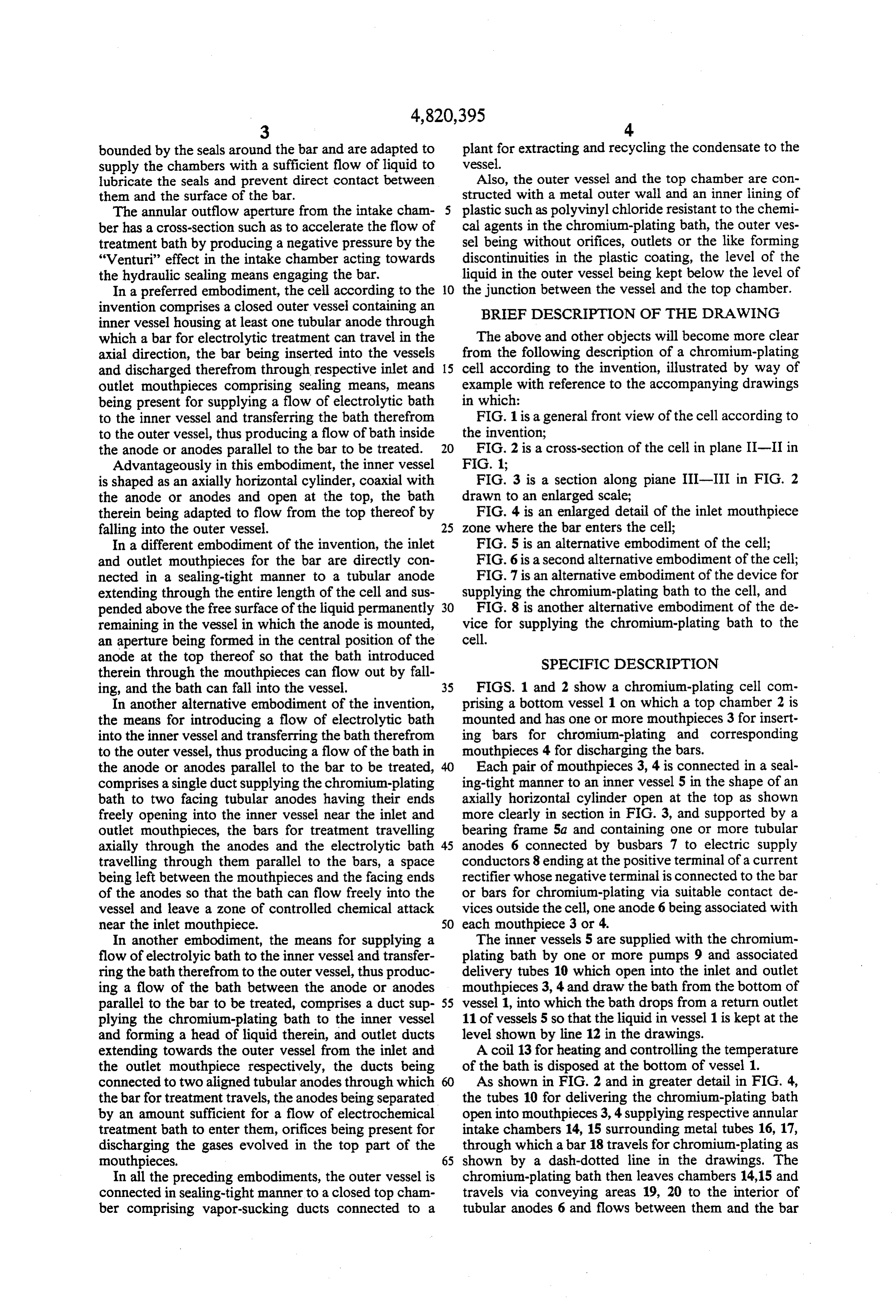
bounded by the seals around the bar and are adapted to plant for extracting and recycling the condensate to the supply the chambers with a sufficient flow of liquid to vessel.
lubricate the seals and prevent direct contact between Also, the outer vessel and the top chamber are con them and the surface of the bar. structed with a metal outer wall and an inner lining of The annular outflow aperture from the intake cham 5 plastic such as polyvinyl chloride resistant to the chemi ber has a cross-section such as to accelerate the flow of cal agents in the chromium-plating bath, the outer ves treatment bath by producing a negative pressure by the sel being without orifices, outlets or the like forming "Venturi' effect in the intake chamber acting towards discontinuities in the plastic coating, the level of the the hydraulic sealing means engaging the bar. liquid in the outer vessel being kept below the level of In a preferred embodiment, the cell according to the O the junction between the vessel and the top chamber. invention comprises a closed outer vessel containing an BRIEF DESCRIPTION OF THE DRAWING inner vessel housing at least one tubular anode through which a bar for electrolytic treatment can travel in the The above and other objects will become more clear axial direction, the bar being inserted into the vessels from the following description of a chromium-plating and discharged therefrom through respective inlet and 15 cell according to the invention, illustrated by way of outlet mouthpieces comprising sealing means, means example with reference to the accompanying drawings being present for supplying a flow of electrolytic bath in which:
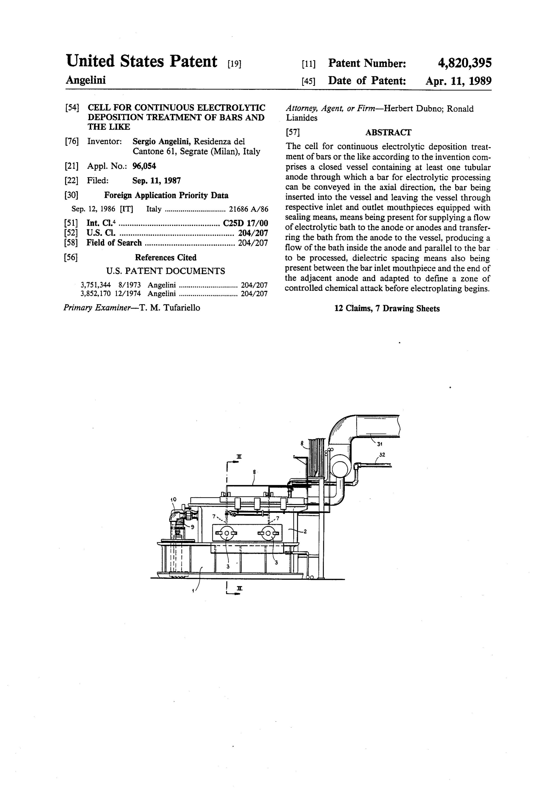
to the inner vessel and transferring the bath therefrom FIG. 1 is a general front view of the cell according to to the outer vessel, thus producing a flow of bath inside the invention;
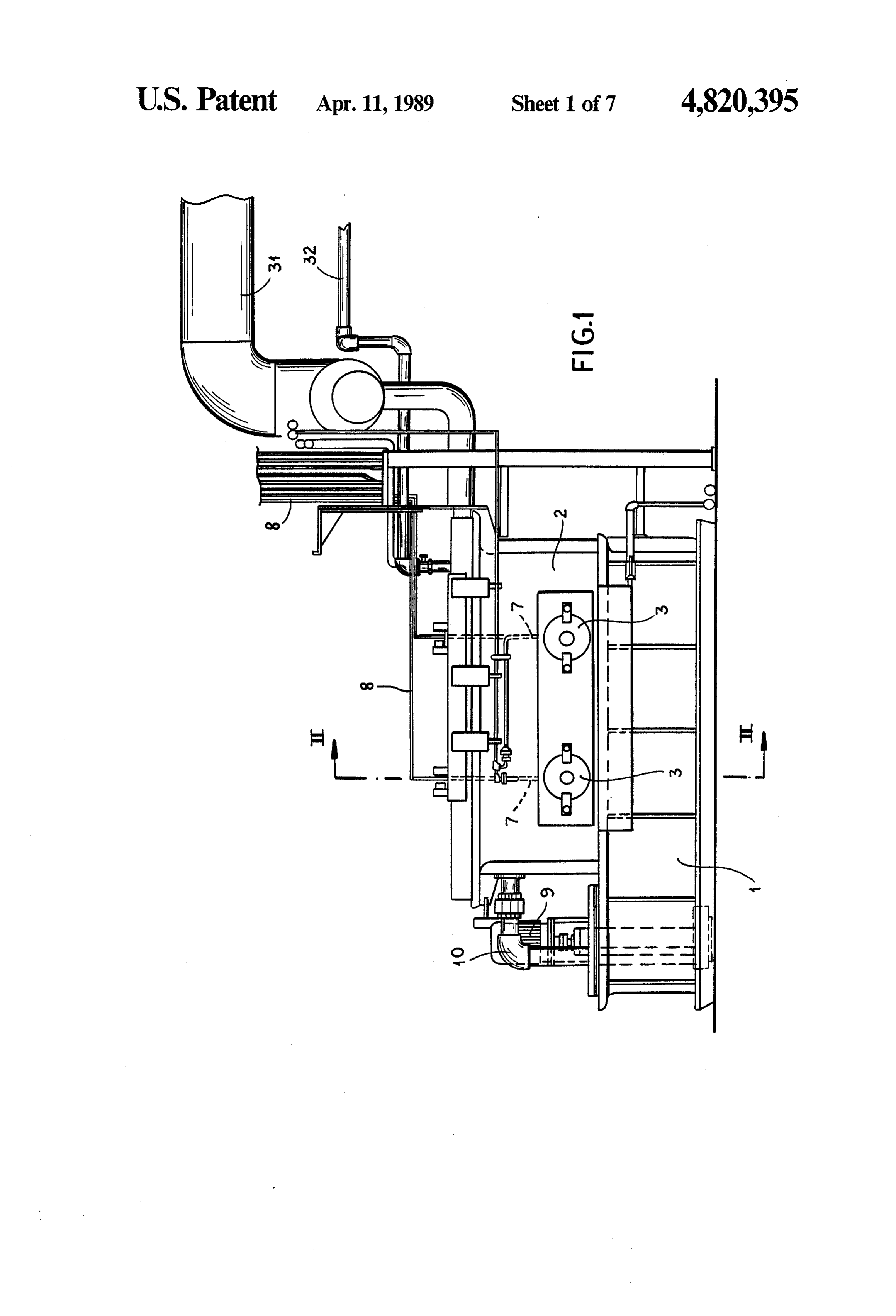
the anode or anodes parallel to the bar to be treated. FIG. 2 is a cross-section of the cell in plane II-II in Advantageously in this embodiment, the inner vessel FIG. 1;
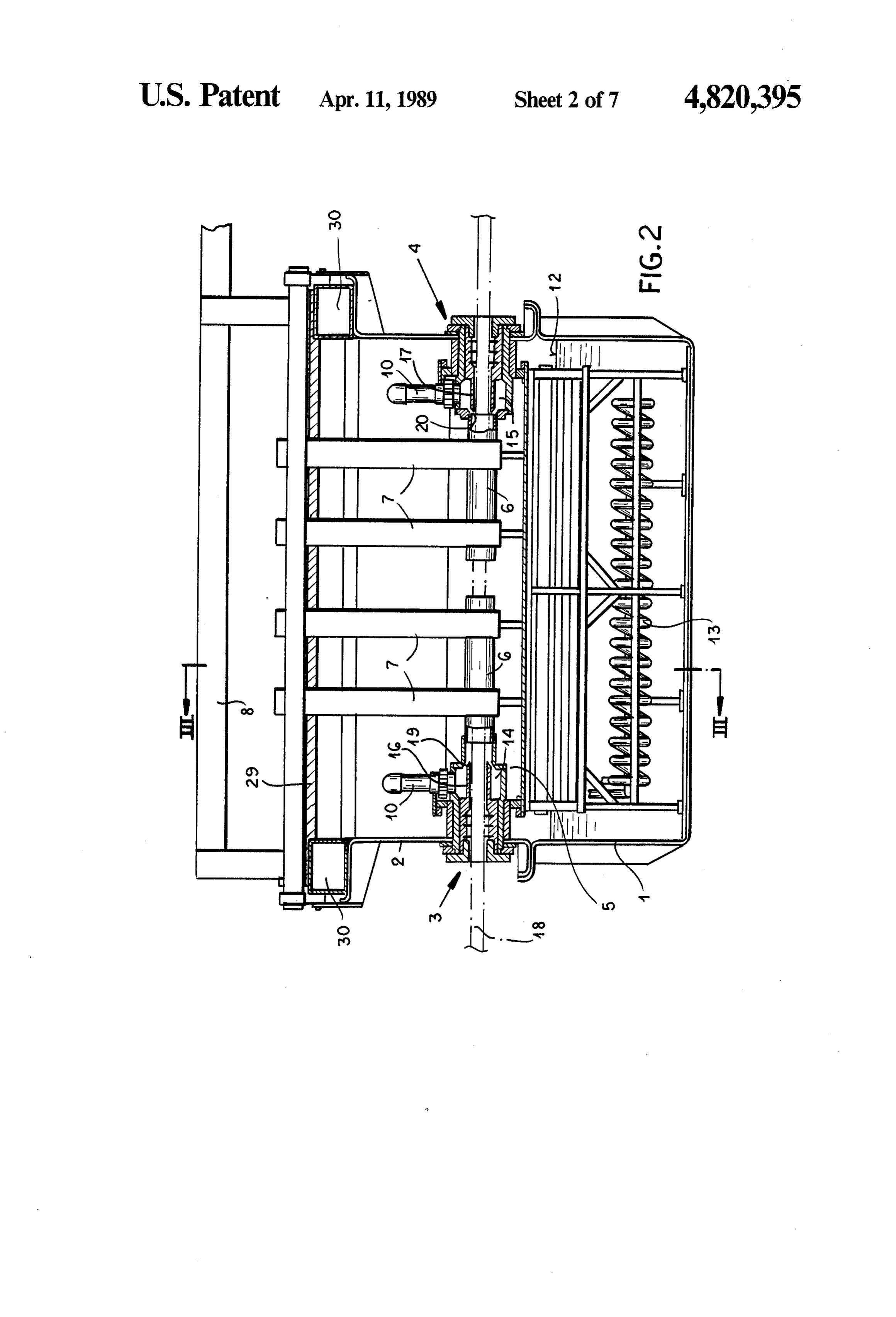
is shaped as an axially horizontal cylinder, coaxial with FIG. 3 is a section along piane III-III in FIG. 2 the anode or anodes and open at the top, the bath drawn to an enlarged scale;
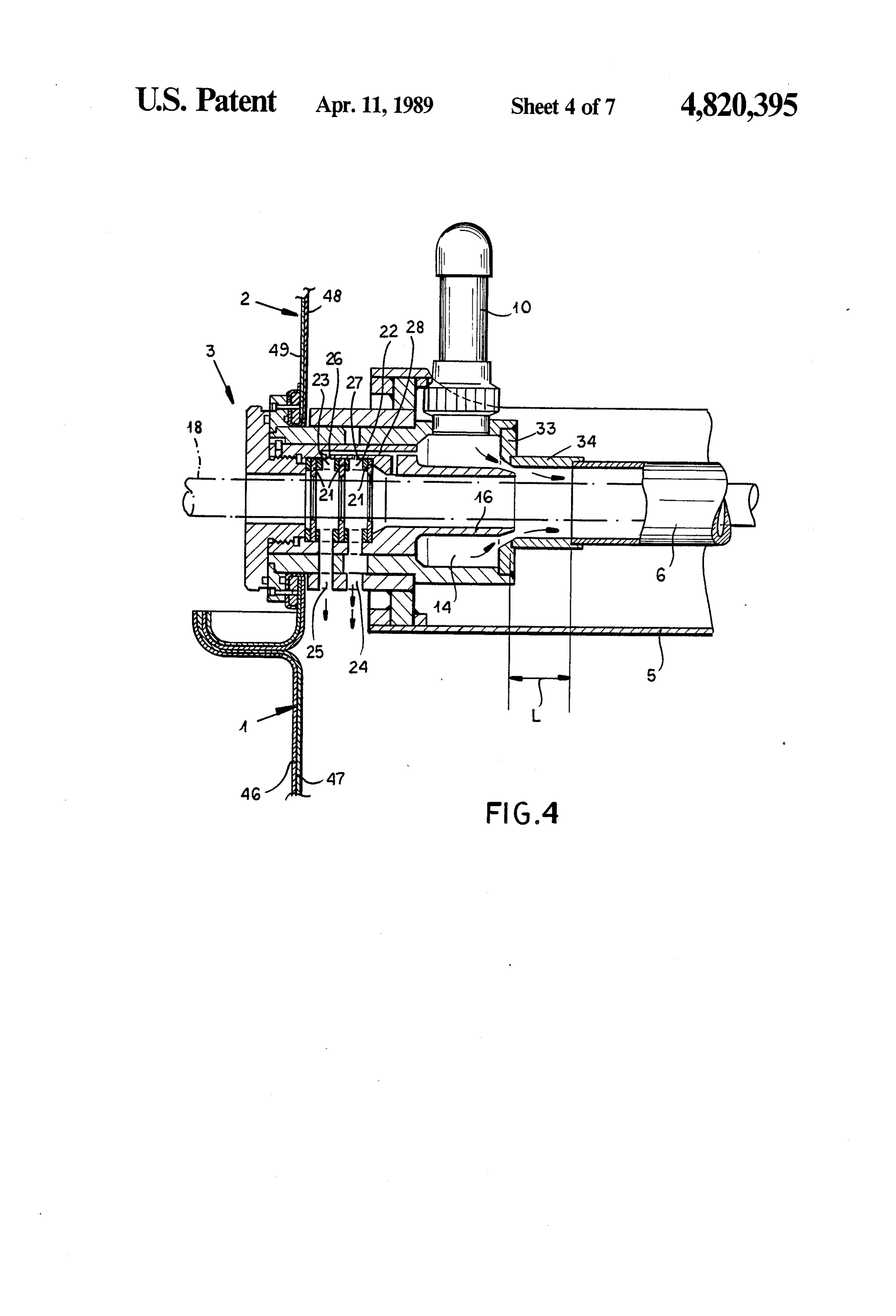
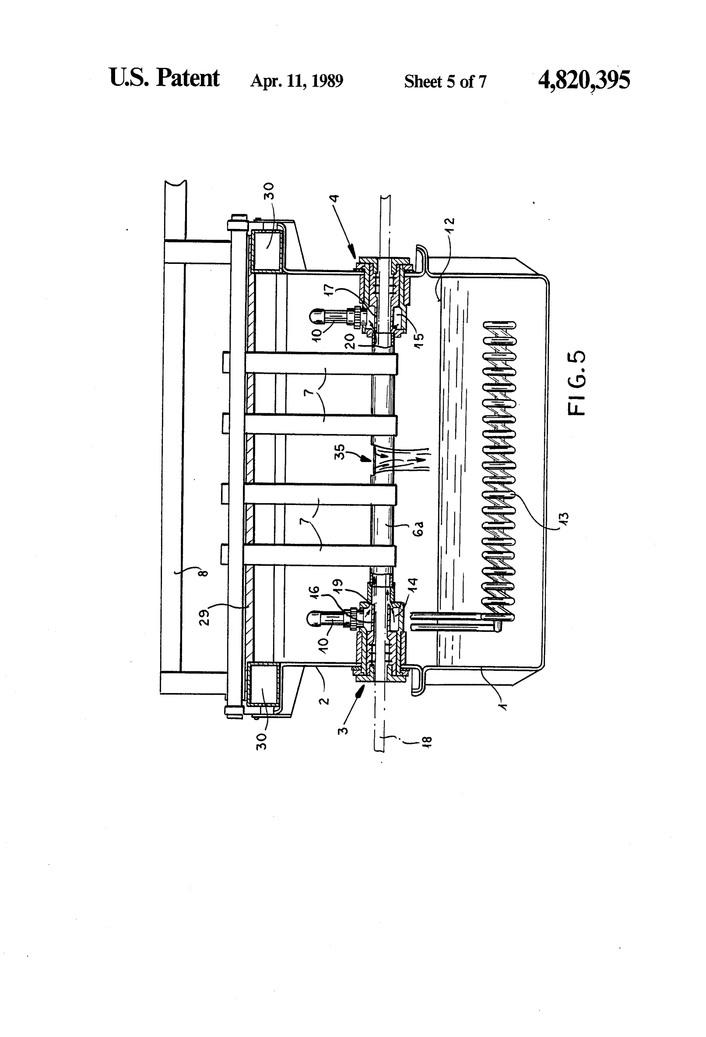
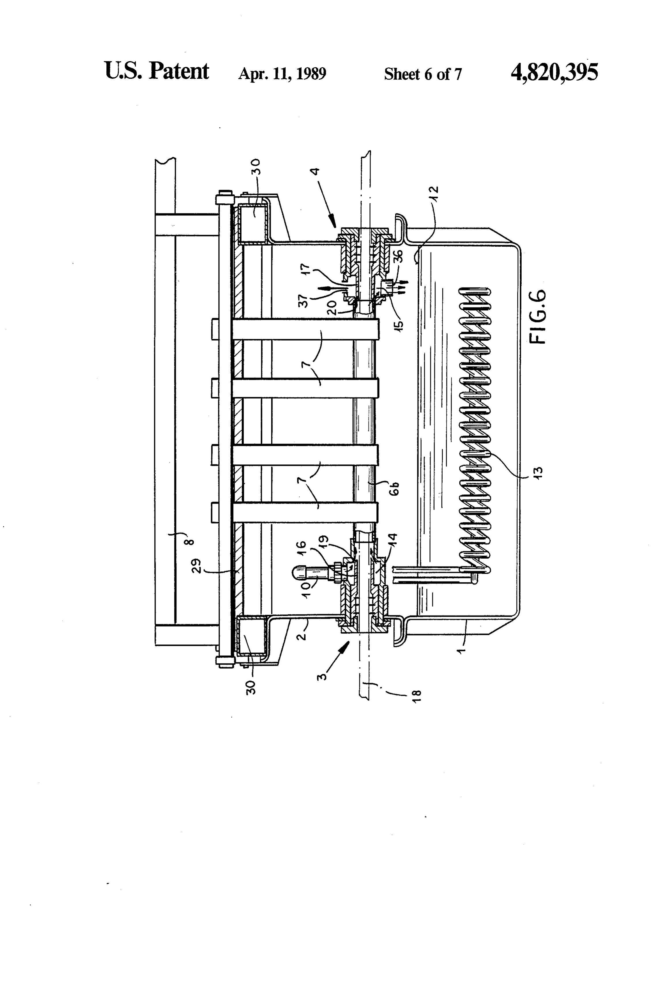
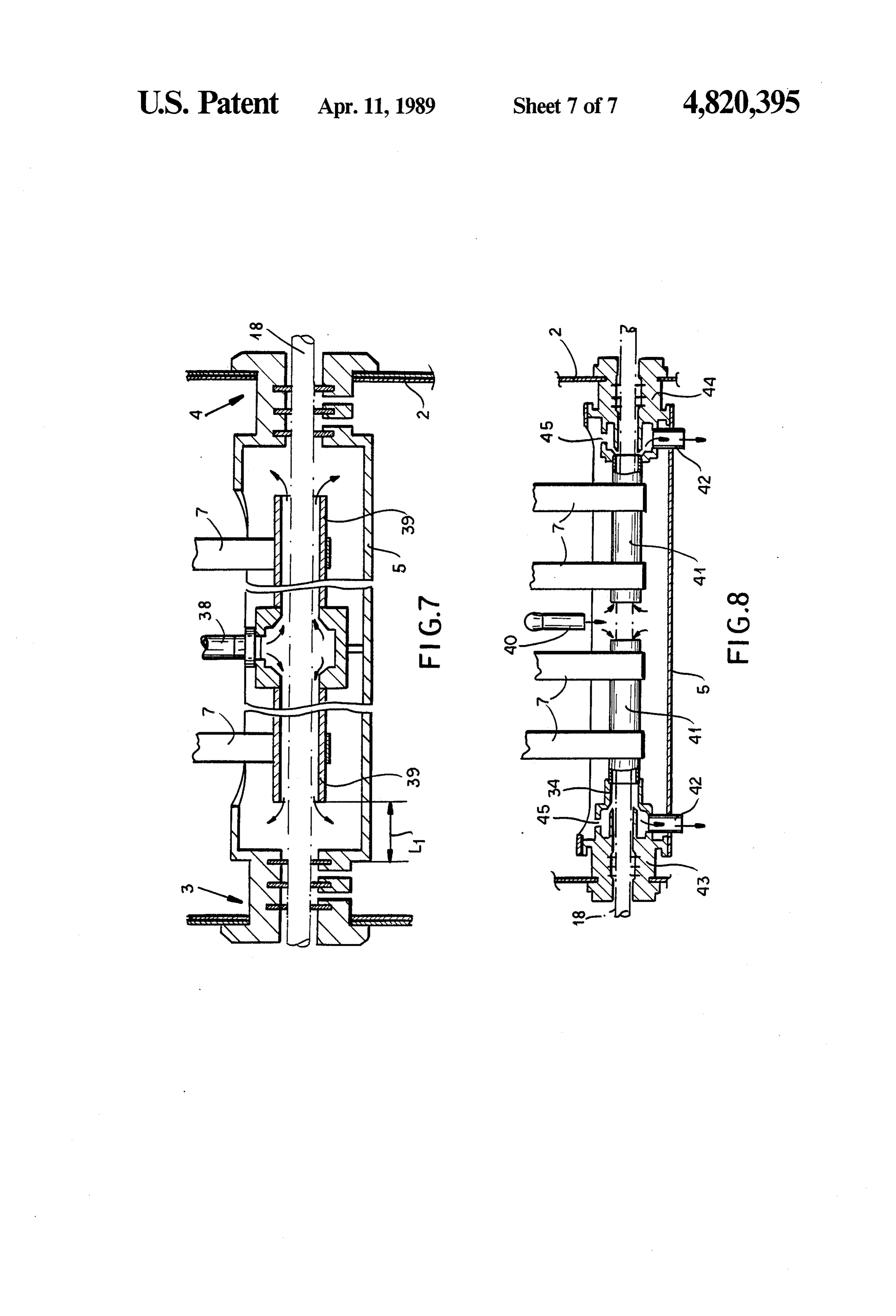
therein being adapted to flow from the top thereof by FIG. 4 is an enlarged detail of the inlet mouthpiece falling into the outer vessel. 25 zone where the bar enters the cell; In a different embodiment of the invention, the inlet FIG. 5 is an alternative embodiment of the cell; and outlet mouthpieces for the bar are directly con FIG. 6 is a second alternative embodiment of the cell; nected in a sealing-tight manner to a tubular anode FIG. 7 is an alternative embodiment of the device for extending through the entire length of the cell and sus supplying the chromium-plating bath to the cell, and pended above the free surface of the liquid permanently 30 FIG. 8 is another alternative embodiment of the de remaining in the vessel in which the anode is mounted, vice for supplying the chromium-plating bath to the an aperture being formed in the central position of the cell.
anode at the top thereof so that the bath introduced SPECIFIC DESCRIPTION therein through the mouthpieces can flow out by fall ing, and the bath can fall into the vessel. 35 FIGS. 1 and 2 show a chromium-plating cell com In another alternative embodiment of the invention, prising a bottom vessel 1 on which a top chamber 2 is the means for introducing a flow of electrolytic bath mounted and has one or more mouthpieces 3 for insert into the inner vessel and transferring the bath therefrom ing bars for chromium-plating and corresponding to the outer vessel, thus producing a flow of the bath in mouthpieces 4 for discharging the bars. the anode or anodes parallel to the bar to be treated, Each pair of mouthpieces 3, 4 is connected in a seal comprises a single duct supplying the chromium-plating ing-tight manner to an inner vessel 5 in the shape of an bath to two facing tubular anodes having their ends axially horizontal cylinder open at the top as shown freely opening into the inner vessel near the inlet and more clearly in section in FIG. 3, and supported by a outlet mouthpieces, the bars for treatment travelling bearing frame 5a and containing one or more tubular axially through the anodes and the electrolytic bath 45 anodes 6 connected by busbars 7 to electric supply travelling through them parallel to the bars, a space conductors 8 ending at the positive terminal of a current being left between the mouthpieces and the facing ends rectifier whose negative terminal is connected to the bar of the anodes so that the bath can flow freely into the or bars for chromium-plating via suitable contact de vessel and leave a zone of controlled chemical attack vices outside the cell, one anode 6 being associated with near the inlet mouthpiece. 50 each mouthpiece 3 or 4.
In another embodiment, the means for supplying a The inner vessels 5 are supplied with the chromium flow of electrolyic bath to the inner vessel and transfer plating bath by one or more pumps 9 and associated ring the bath therefrom to the outer vessel, thus produc delivery tubes 10 which open into the inlet and outlet ing a flow of the bath between the anode or anodes mouthpieces 3, 4 and draw the bath from the bottom of parallel to the bar to be treated, comprises a duct sup 55 vessel 1, into which the bath drops from a return outlet plying the chromium-plating bath to the inner vessel 11 of vessels 5 so that the liquid in vessel 1 is kept at the and forming a head of liquid therein, and outlet ducts level shown by line 12 in the drawings. extending towards the outer vessel from the inlet and A coil 13 for heating and controlling the temperature the outlet mouthpiece respectively, the ducts being of the bath is disposed at the bottom of vessel 1. connected to two aligned tubular anodes through which As shown in FIG. 2 and in greater detail in FIG. 4, the bar for treatment travels, the anodes being separated the tubes 10 for delivering the chromium-plating bath by an amount sufficient for a flow of electrochemical open into mouthpieces 3, 4 supplying respective annular treatment bath to enter them, orifices being present for intake chambers 14, 15 surrounding metal tubes 16, 17, discharging the gases evolved in the top part of the through which a bar 18 travels for chromium-plating as mouthpieces. 65 shown by a dash-dotted line in the drawings. The In all the preceding embodiments, the outer vessel is chromium-plating bath then leaves chambers 14,15 and connected in sealing-tight manner to a closed top cham travels via conveying areas 19, 20 to the interior of ber comprising vapor-sucking ducts connected to a tubular anodes 6 and flows between them and the bar
Page 11
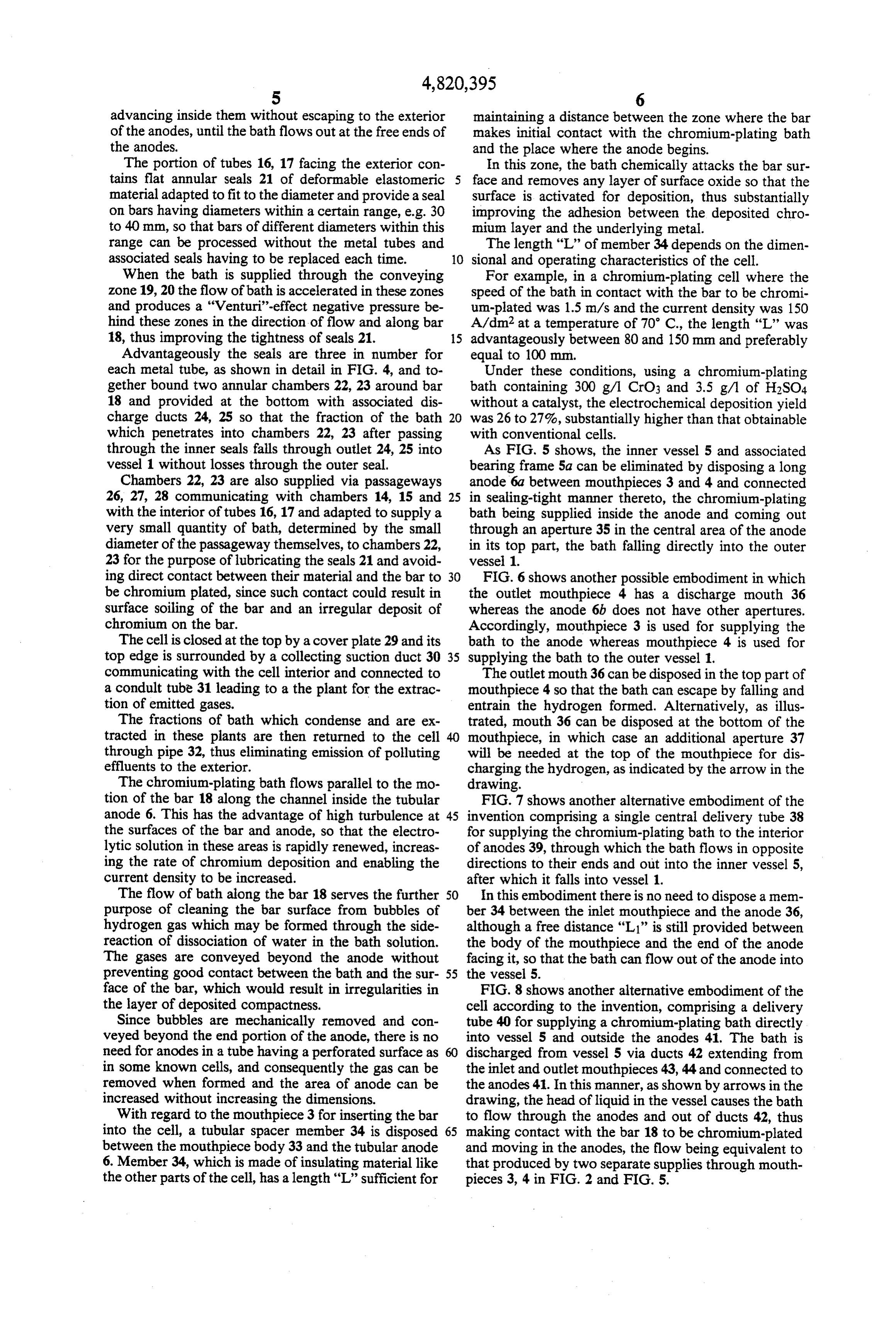
advancing inside them without escaping to the exterior maintaining a distance between the zone where the bar of the anodes, until the bath flows out at the free ends of makes initial contact with the chromium-plating bath the anodes. and the place where the anode begins. The portion of tubes 16, 17 facing the exterior con In this zone, the bath chemically attacks the bar sur tains flat annular seals 21 of deformable elastomeric 5 face and removes any layer of surface oxide so that the material adapted to fit to the diameter and provide a seal surface is activated for deposition, thus substantially on bars having diameters within a certain range, e.g. 30 improving the adhesion between the deposited chro to 40 mm, so that bars of different diameters within this mium layer and the underlying metal. range can be processed without the metal tubes and The length "L' of member 34 depends on the dimen associated seals having to be replaced each time. 10 sional and operating characteristics of the cell. When the bath is supplied through the conveying For example, in a chromium-plating cell where the zone 19, 20 the flow of bath is accelerated in these zones speed of the bath in contact with the bar to be chromi and produces a "Venturi'-effect negative pressure be um-plated was 1.5 m/s and the current density was 150 hind these zones in the direction of flow and along bar A/dm2 at a temperature of 70° C., the length "L' was 18, thus improving the tightness of seals 21. 15 advantageously between 80 and 150 mm and preferably Advantageously the seals are three in number for equal to 100 mm.
each metal tube, as shown in detail in FIG. 4, and to Under these conditions, using a chromium-plating gether bound two annular chambers 22, 23 around bar bath containing 300 g/l CrO3 and 3.5 g/l of H2SO4 18 and provided at the bottom with associated dis without a catalyst, the electrochemical deposition yield charge ducts 24, 25 so that the fraction of the bath 20 was 26 to 27%, substantially higher than that obtainable which penetrates into chambers 22, 23 after passing with conventional cells.
through the inner seals falls through outlet 24, 25 into As FIG. 5 shows, the inner vessel 5 and associated vessel 1 without losses through the outer seal. bearing frame 5a can be eliminated by disposing a long Chambers 22, 23 are also supplied via passageways anode 6a between mouthpieces 3 and 4 and connected 26, 27, 28 communicating with chambers 14, 15 and 25 in sealing-tight manner thereto, the chronium-plating with the interior of tubes 16, 17 and adapted to supply a bath being supplied inside the anode and coming out very small quantity of bath, determined by the small through an aperture 35 in the central area of the anode diameter of the passageway themselves, to chambers 22, in its top part, the bath falling directly into the outer 23 for the purpose of lubricating the seals 21 and avoid vessel 1.
ing direct contact between their material and the bar to 30 FIG. 6 shows another possible embodiment in which be chromium plated, since such contact could result in the outlet mouthpiece 4 has a discharge mouth 36 surface soiling of the bar and an irregular deposit of whereas the anode 6b does not have other apertures. chromium on the bar. Accordingly, mouthpiece 3 is used for supplying the The cell is closed at the top by a cover plate 29 and its bath to the anode whereas mouthpiece 4 is used for top edge is surrounded by a collecting suction duct 30 35 supplying the bath to the outer vessel 1. communicating with the cell interior and connected to The outlet mouth 36 can be disposed in the top part of a condult tube 31 leading to a the plant for the extrac mouthpiece 4 so that the bath can escape by falling and tion of emitted gases. entrain the hydrogen formed. Alternatively, as illus The fractions of bath which condense and are ex trated, mouth 36 can be disposed at the bottom of the tracted in these plants are then returned to the cell 40 mouthpiece, in which case an additional aperture 37 through pipe 32, thus eliminating emission of polluting will be needed at the top of the mouthpiece for dis effluents to the exterior. charging the hydrogen, as indicated by the arrow in the The chromium-plating bath flows parallel to the mo drawing.
tion of the bar 18 along the channel inside the tubular FIG. 7 shows another alternative embodiment of the anode 6. This has the advantage of high turbulence at 45 invention comprising a single central delivery tube 38 the surfaces of the bar and anode, so that the electro for supplying the chronium-plating bath to the interior lytic solution in these areas is rapidly renewed, increas of anodes 39, through which the bath flows in opposite ing the rate of chromium deposition and enabling the directions to their ends and out into the inner vessel 5, current density to be increased. after which it falls into vessel 1. The flow of bath along the bar 18 serves the further 50 In this embodiment there is no need to dispose a mem purpose of cleaning the bar surface from bubbles of ber 34 between the inlet mouthpiece and the anode 36, hydrogen gas which may be formed through the side although a free distance "L' is still provided between reaction of dissociation of water in the bath solution. the body of the mouthpiece and the end of the anode The gases are conveyed beyond the anode without facing it, so that the bath can flow out of the anode into preventing good contact between the bath and the sur- 55 the vessel 5.
face of the bar, which would result in irregularities in FIG. 8 shows another alternative embodiment of the the layer of deposited compactness. cell according to the invention, comprising a delivery Since bubbles are mechanically removed and con tube 40 for supplying a chromium-plating bath directly veyed beyond the end portion of the anode, there is no into vessel 5 and outside the anodes 41. The bath is need for anodes in a tube having a perforated surface as 60 discharged from vessel 5 via ducts 42 extending from in some known cells, and consequently the gas can be the inlet and outlet mouthpieces 43,44 and connected to removed when formed and the area of anode can be the anodes 41. In this manner, as shown by arrows in the increased without increasing the dimensions. drawing, the head of liquid in the vessel causes the bath With regard to the mouthpiece 3 for inserting the bar to flow through the anodes and out of ducts 42, thus into the cell, a tubular spacer member 34 is disposed 65 making contact with the bar 18 to be chromium-plated between the mouthpiece body 33 and the tubular anode and moving in the anodes, the flow being equivalent to 6. Member 34, which is made of insulating material like that produced by two separate supplies through mouth the other parts of the cell, has a length "L' sufficient for pieces 3, 4 in FIG. 2 and FIG. 5.
Page 12
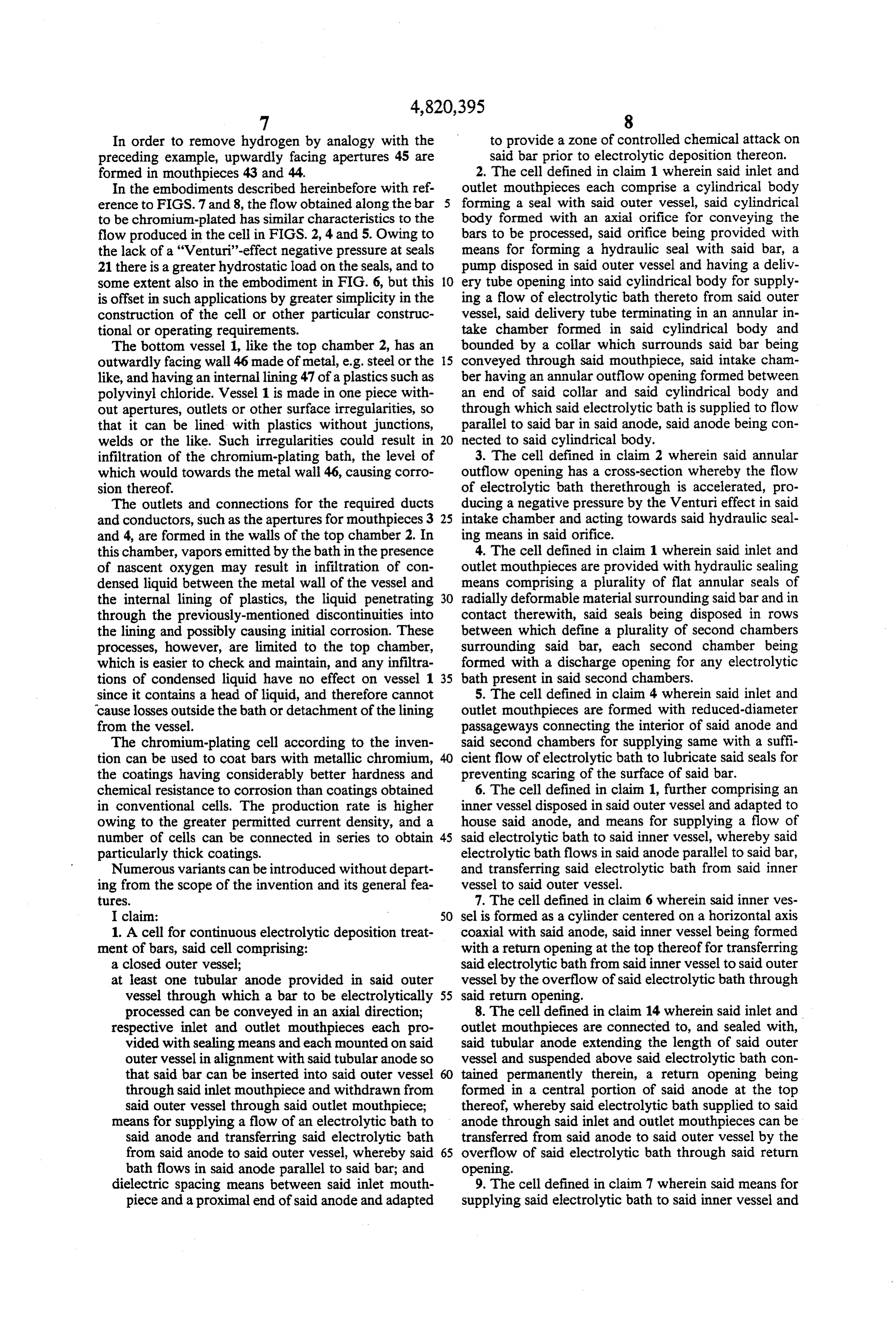
In order to remove hydrogen by analogy with the to provide a zone of controlled chemical attack on preceding example, upwardly facing apertures 45 are said bar prior to electrolytic deposition thereon. formed in mouthpieces 43 and 44. 2. The cell defined in claim 1 wherein said inlet and In the embodiments described hereinbefore with ref outlet mouthpieces each comprise a cylindrical body erence to FIGS. 7 and 8, the flow obtained along the bar 5 forming a seal with said outer vessel, said cylindrical to be chromium-plated has similar characteristics to the body formed with an axial orifice for conveying the flow produced in the cell in FIGS. 2, 4 and 5. Owing to bars to be processed, said orifice being provided with the lack of a "Venturi'-effect negative pressure at seals means for forming a hydraulic seal with said bar, a 21 there is a greater hydrostatic load on the seals, and to pump disposed in said outer vessel and having a deliv some extent also in the embodiment in FIG. 6, but this 10 ery tube opening into said cylindrical body for supply is offset in such applications by greater simplicity in the ing a flow of electrolytic bath thereto from said outer construction of the cell or other particular construc vessel, said delivery tube terminating in an annular in tional or operating requirements. take chamber formed in said cylindrical body and The bottom vessel 1, like the top chamber 2, has an bounded by a collar which surrounds said bar being outwardly facing wall 46 made of metal, e.g. steel or the 15 conveyed through said mouthpiece, said intake cham like, and having an internal lining 47 of a plastics such as ber having an annular outflow opening formed between polyvinyl chloride. Vessel 1 is made in one piece with an end of said collar and said cylindrical body and out apertures, outlets or other surface irregularities, so through which said electrolytic bath is supplied to flow that it can be lined with plastics without junctions, parallel to said bar in said anode, said anode being con welds or the like. Such irregularities could result in 20 nected to said cylindrical body.
infiltration of the chromium-plating bath, the level of 3. The cell defined in claim 2 wherein said annular which would towards the metal wall 46, causing corro outflow opening has a cross-section whereby the flow sion thereof. of electrolytic bath therethrough is accelerated, pro The outlets and connections for the required ducts ducing a negative pressure by the Venturi effect in said and conductors, such as the apertures for mouthpieces 3 25 intake chamber and acting towards said hydraulic seal and 4, are formed in the walls of the top chamber 2. In ing means in said orifice.
this chamber, vapors emitted by the bath in the presence 4. The cell defined in claim 1 wherein said inlet and of nascent oxygen may result in infiltration of con outlet mouthpieces are provided with hydraulic sealing densed liquid between the metal wall of the vessel and means comprising a plurality of flat annular seals of the internal lining of plastics, the liquid penetrating 30 radially deformable material surrounding said bar and in through the previously-mentioned discontinuities into contact therewith, said seals being disposed in rows the lining and possibly causing initial corrosion. These between which define a plurality of second chambers processes, however, are limited to the top chamber, surrounding said bar, each second chamber being which is easier to check and maintain, and any infiltra formed with a discharge opening for any electrolytic tions of condensed liquid have no effect on vessel 1 35 bath present in said second chambers. since it contains a head of liquid, and therefore cannot 5. The cell defined in claim 4 wherein said inlet and cause losses outside the bath or detachment of the lining outlet mouthpieces are formed with reduced-diameter from the vessel. passageways connecting the interior of said anode and The chromium-plating cell according to the inven said second chambers for supplying same with a suffi tion can be used to coat bars with metallic chromium, cient flow of electrolytic bath to lubricate said seals for the coatings having considerably better hardness and preventing scaring of the surface of said bar. chemical resistance to corrosion than coatings obtained 6. The cell defined in claim 1, further comprising an in conventional cells. The production rate is higher inner vessel disposed in said outer vessel and adapted to owing to the greater permitted current density, and a house said anode, and means for supplying a flow of number of cells can be connected in series to obtain 45 said electrolytic bath to said inner vessel, whereby said particularly thick coatings. electrolytic bath flows in said anode parallel to said bar, Numerous variants can be introduced without depart and transferring said electrolytic bath from said inner ing from the scope of the invention and its general fea vessel to said outer vessel.
tures. 7. The cell defined in claim 6 wherein said inner ves I claim: 50 sel is formed as a cylinder centered on a horizontal axis 1. A cell for continuous electrolytic deposition treat coaxial with said anode, said inner vessel being formed ment of bars, said cell comprising: with a return opening at the top thereof for transferring a closed outer vessel; said electrolytic bath from said inner vessel to said outer at least one tubular anode provided in said outer vessel by the overflow of said electrolytic bath through vessel through which a bar to be electrolytically 55 said return opening.
processed can be conveyed in an axial direction; 8. The cell defined in claim 14 wherein said inlet and respective inlet and outlet mouthpieces each pro outlet mouthpieces are connected to, and sealed with, vided with sealing means and each mounted on said said tubular anode extending the length of said outer outer vessel in alignment with said tubular anode so vessel and suspended above said electrolytic bath con that said bar can be inserted into said outer vessel 60 tained permanently therein, a return opening being through said inlet mouthpiece and withdrawn from formed in a central portion of said anode at the top said outer vessel through said outlet mouthpiece; thereof, whereby said electrolytic bath supplied to said means for supplying a flow of an electrolytic bath to anode through said inlet and outlet mouthpieces can be said anode and transferring said electrolytic bath transferred from said anode to said outer vessel by the from said anode to said outer vessel, whereby said 65 overflow of said electrolytic bath through said return bath flows in said anode parallel to said bar; and opening.
dielectric spacing means between said inlet mouth 9. The cell defined in claim 7 wherein said means for piece and a proximal end of said anode and adapted supplying said electrolytic bath to said inner vessel and
Page 13
transferring same therefrom to said outer vessel in cating with a respective anode, and a respective orifice cludes a delivery tube supplying said electrolytic bath formed in an upper portion of said inlet and outlet to said anode in a flow parallel to said bar, said anode mouthpieces for discharging gases evolved therein. having oppositely directed free ends spaced from said 11. The cell defined in claim 1 wherein said outer inlet and outlet mouthpieces for the flow of said electro vessel has an upper chamber forming a sealed junction lytic bath into said inner vessel and to provide said Zone therewith and provided with a vapor-drawing duct of controlled chemical attack.
10. The cell defined in claim 6 wherein said means for connected to an apparatus for extracting a condensate supplying a flow of said electrolytic bath to said inner from said vapor and recycling same to said outer vessel. vessel and transferring same to said outer vessel in 10 12. The cell defined in claim 1 wherein said outer cludes a delivery tube for supplying said electrolytic vessel and said upper chamber are formed with a metal bath to said inner vessel and forming a head of said outer wall having a synthetic resin lining resistant to electrolytic bath therein, a respective anode extending chemical agents present in said electrolytic bath, said from said inlet and outlet mouthpieces toward one an outer vessel being free of orifices and outlets which can other, each anode having a respective free end opening 15 form junctions or welds in the lining, the level of said at said delivery tube for the flow of said electrolytic electrolytic bath in said outer vessel being kept below bath parallel to said bar in each anode, a respective said sealed junction formed between said outer vessel outlet tube extending from said inlet and outlet mouth and said upper chamber.
pieces into said outer vessel, each outlet tube communi k k xt x k

Provenance
- Collection
- Cited prior art
- Original PDF
- patentimages.storage.googleapis.com →
- Filed
- 1987-09-11
- Pages
- 13
- Method
- pdftotext (the PDF's own text layer) + pdftoppm 300dpi page scans
- Source
- Google Patents bibliographic record
- Granted
- 1989-04-11
- Inventors
- Sergio Angelini
- Transcribed from
- patentimages.storage.googleapis.com →