patent · US3572297
Hydrogen fueled internal combustion engine
23 March 1971
Page 1
Drawing sheet — no readable text.
Page 2
Drawing sheet — no readable text.
Page 3
Drawing sheet — no readable text.
Page 4
Drawing sheet — no readable text.
Page 5
United States Patent Office 3,572,297 Patented Mar. 23, 1971
as the oxidizer was found to produce significantly in 3,572,297 creased thermal stress in the engine and led to severe cor HYDROGEN FUELED INTERNAL rosion, leakage and lubrication problems. In the Vickers
COMBUSTON ENGINE
Richard G. Murray, Perkins, Okla., assignor to Roger J. and Marquardt engines, ignition delays and detonation Schoeppel and Roger C. Allen, Stillwater, Okla. 5 occurred to an undesirable extent. Both projects were Filed Jan. 26, 1970, Ser. No. 5,791 abandoned before a practical engine was developed.
U.S. C. 123-1 21 Claims BRIEF DESCRIPTION OF THE
PRESENT INVENTION
10 The present invention provides a practical hydrogen
ABSTRACT OF THE DISCLOSURE
This invention relates to an internal combustion engine fueled internal combustion engine which, through the unique combined concepts of direct hydrogen injection, operated by direct injection of hydrogen into the cylin employment ders thereof. Hydrogen is mixed with a portion of the drogen duringof itsair injection as the oxidizer, and igniting the hy and sustaining the combus air in the cylinders to form a combustible mixture which 5 tion over a specific range of the engine cycle, poses no is ignited and burned concurrently with injection over a significant problem of pre-ignition, detonation or excessive portion of the expansion stroke and in some cases a por thermal stress. The engine differs from the previously tion of the compression stroke. Dual poppet valves are known systems basically in how and when hydrogen fuel used for injecting the hydrogen and are timed to open is injected and ignited, and in the oxidizer used to yield and close in response to sensed engine operating param 20 the combustible mixture. In another aspect, the inventive eters.
concepts herein disclosed encompass a novel fuel injector valve, and control devices used to optimize the actuation
BACKGROUND OF THE INVENTION of this valve.
Field of the invention Broadly described, the present invention comprises a method of hydrogen fueling an internal combustion en
This invention relates to internal combustion engines gine which includes the steps of passing air into the cylin operated by injection of a combustible gaseous fuel di der of the engine; injecting substantially pure hydrogen rectly into the cylinders of the engine. In one more re directly into the cylinder of the engine beginning the stricted aspect, the invention relates to injection valves useful for injecting hydrogen into the cylinders of inter 30 injection at a time which is between 60 and 0° before top dead center of the compression stroke, igniting the nal combustion engines. hydrogen immediately after the commencement of in Brief description of the prior art jection by means of a spark plug, hot wire (glow plug), hot air (compression ignition), or catalytically; continuing
It has been heretofore proposed to fuel internal com 35 to inject hydrogen directly into the cylinder of the en bustion engines with hydrogen gas. This fuel burns in air gine until between 0° and 90° after top dead center dur to yield water as the main product of combustion, and ing the expansion stroke; and substantially concurrently therefore fewer atmospheric contaminants result from with the direct injection of hydrogen, sustaining combus its use under controlled conditions. By controlling the air tion of the hydrogen.
fuel ratio, relatively lower temperatures may be produced 40 In a different aspect, the invention relates to the appara than when fossil fuels are employed. tus by which the described method is carried out, includ The use of hydrogen as a fuel for internal combustion ing an internal combustion engine having at least one engines was demonstrated in the 1930's by the German cylinder, single or multiple poppet injector valves mounted engineer, Rudolph Erren. His work is epitomized in U.S. on each cylinder for injecting hydrogen gas directly into Pat. 2,183,674, U.S. Pat. 1,901,709, British Pat. 462,605, the respective cylinder, and means for automatically con and British Pat. 364, 180, and included a proposal for di trolling the opening and closing of the poppet valves in rectly injecting hydrogen into the cylinders of the engine response to certain engine operating parameters and means early during the compression stroke and terminating such for igniting said hydrogen gas. In one construction with injection not later than 80 before top dead center during dual poppet valves, the valves are coaxially and concen the compression stroke (British Pat. 462,605). Erren's 50 trically disposed and are each connected to valve stems major operational problem and one that he was not able which are individually actuated in timed sequence by a to overcome was detonation within the combustion cham pair of sequentially energized solenoids to thus open the ber. valves, and are returned to a position of closure by suit In the late 1940's, King, Wallace and Mahapatra at the able spring elements after de-energization of the respec University of Toronto worked with a co-operative fuel 55 tive solenoids.
research (CFR) internal combustion research engine in An important object of the invention is to provide a studying the nuclear theory of ignition for various hydro practical internal combustion engine with which atmos gen-air mixtures over a range of pressure ratios. A hydro pheric contamination resulting from engine operation is gen-air mixture was admitted to the cylinder through a Substantially reduced as compared to internal combus carburetor. Unless frequent, regular and thorough sched 60 tion engines now in use.
ules for cleaning the combustion chamber were set up, An additional object of the invention is to provide a severe knocking due to detonation, and pre-ignition made practical internal combustion engine which does not em it impossible to run the engine on any but the leanest ploy fossil fuels in its operation. Non-fossil fuels, as here mixtures and lowest compression ratios. inafter used, is defined as fuels excluding gasoline, kero In 1963, the Vickers division of the Sperry Rand Cor 65 Sene and fuel oils.
poration sought to produce a hydrogen fueled internal A further object of the invention is to provide a hydro combustion engine for use with spacecraft. The Mar gen fueled internal combustion engine in which detona quardt Corporation of Van Nuys, Calif., undertook a tion and preignition are minimized. similar project. Both the Vickers and Marquardt projects Another object of the invention is to provide a hydrogen utilized a mixture of hydrogen and oxygen with hydro 70 fueled internal combustion engine which is safer to op gen serving as the working fluid and the engine exhaust erate than hydrogen fueled internal combustion engines ing into a vacuum. The use of substantially pure oxygen previously built.
Page 6
Yet another object of the invention is to provide a hy can shaft 20 and are connected through a suitable ball drogen fueled internal combustion engine which does not joint connection, or other movement-facilitating connec become fouled as quickly, or require cleaning of the com tion, to rocker arms 44 and 46 (FIG. 4) disposed at the up bustion chamber as frequently, as the engines of this type per ends of the push rod subassemblies 26 and 28, respec tively.
which have been previously proposed. 5
Another object of the invention is to provide a hydrogen E. rocker arms are similar in construction, and include fueled internal combustion engine which is characterized elongated shaft portions 44a and 46a (FIG. 4A), respec in having a relatively long and trouble-free operating life. tively. Each of the rocker arms 44 and 46 has a sleeve Additional objects and advantages of the invention will portion 44b and 46b, respectively, at the end thereof op become apparent as the following detailed description of O posite its end which is connected to the respective push the invention is read in conjunction with the accompanying rod subassembly 26 or 28, and the sleeves of the rocker drawings which illustrate the invention as it relates to a arms are journaled on a pair of shafts 48 and 50 which single cylinder engine. extend between the walls of an injector housing designated BRIEF DESCRIPTION OF THE DRAWINGS generally by reference numeral 52. Extending in a reverse direction from the sleeve 44b and 46b and parallel to the
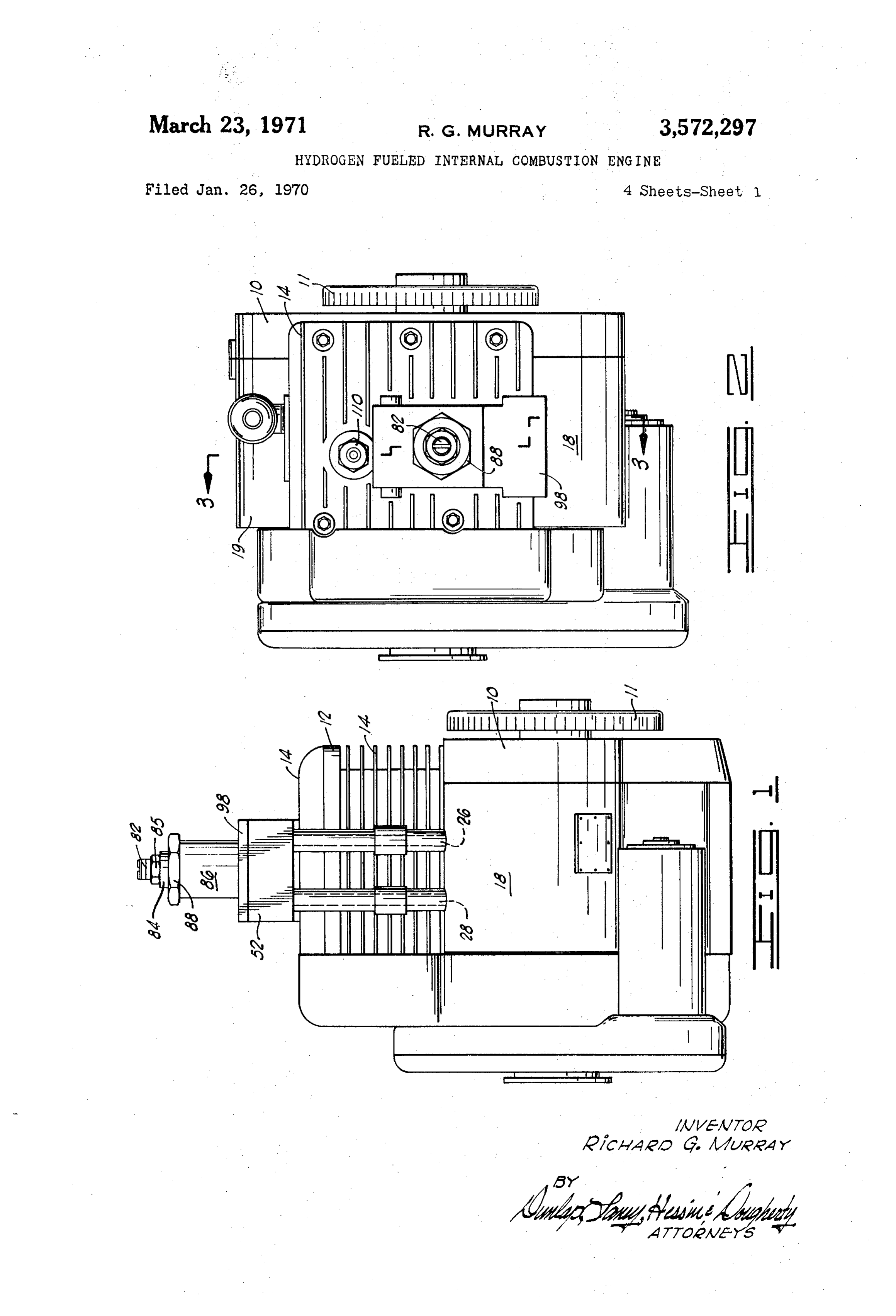
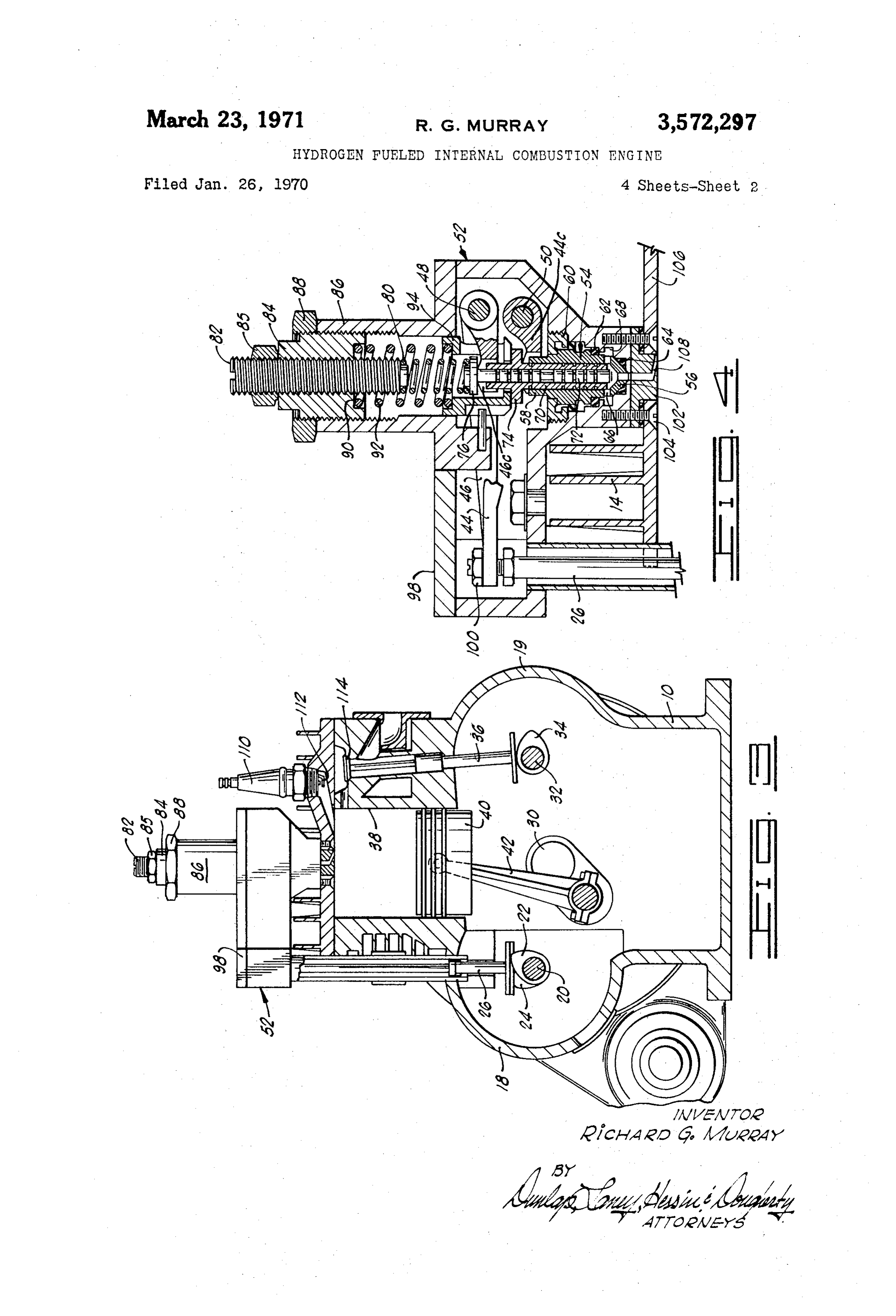
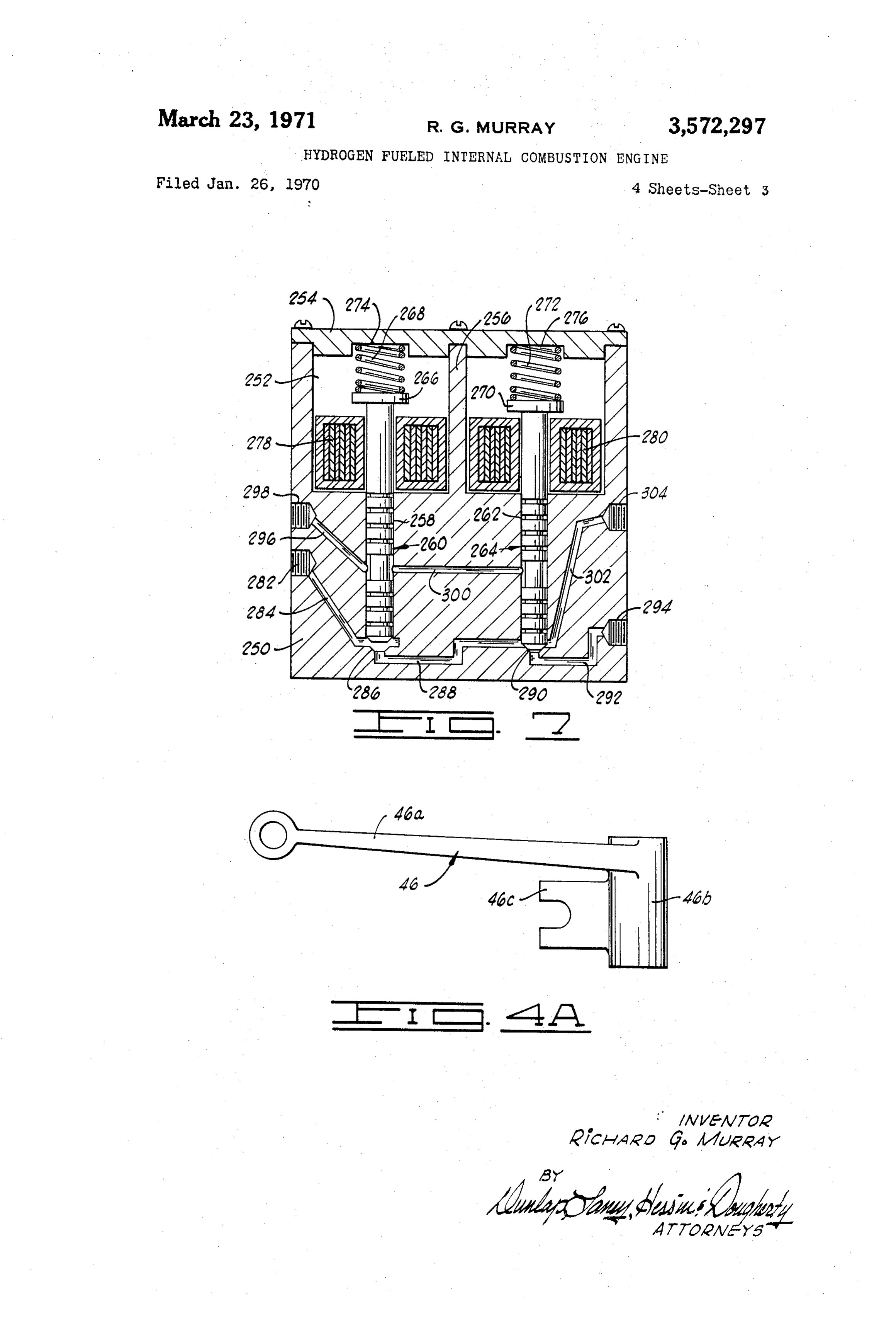
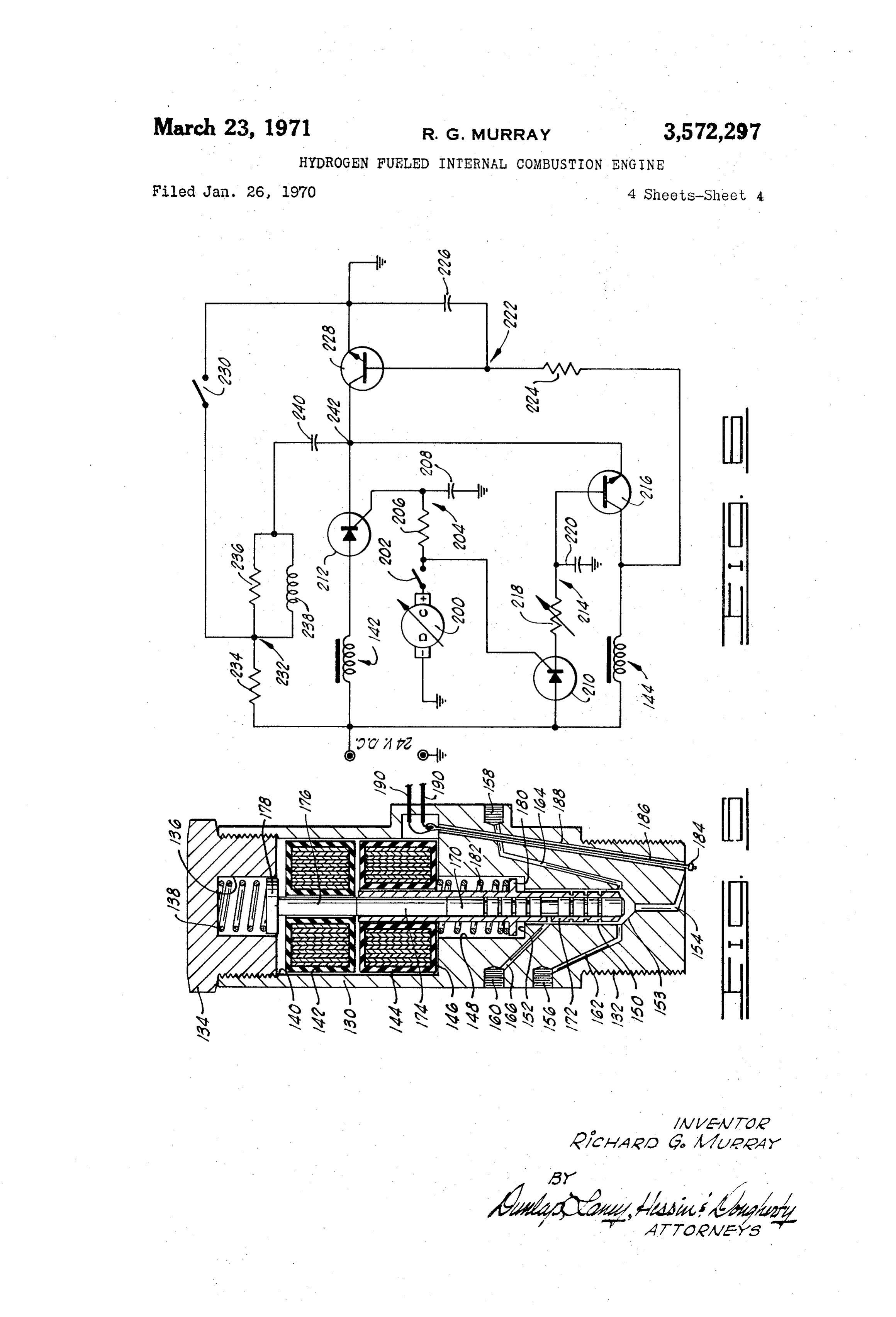
FIG. 1 is a side elevation view of an internal combus shaft portions 44a and 46a, respectively, are bifurcated tion engine constructed in accordance with the present in lifting plates 44c and 46c, respectively. vention. The rocker arms 44 and 46 function, in response to the FIG. 2 is a plan view of the internal combustion engine rotation of the cam shaft 20, to sequentially operate the depicted in FIG. 1. dual valves of a dual poppet valve subassembly designated FIG. 3 is a sectional view taken along line 3-3 of 20 generally by reference numeral 54. The dual poppet valve FIG. 2. subassembly 54 includes a conically tapered valve seat 56 FIG. 4 is an enlarged, partially sectional, partially eleva having a port through the apex or lower end thereof, tional view of one embodiment of a mechanically actuated with the seat being formed on the lower end of a sleeve dual poppet injection valve constituting a subassembly of 58 which has a central bore therethrough communicating the invention. with the hollow interior of the conically tapered seat, FIG. 4A is a detail plan view illustrating a rocker arm and aligned with the port through the seat. The sleeve forming a portion of the mechanical linkage of the hydro 58 carries a shoulder which facilitates its location and gen fueled engine. retention in the injector housing 52 by means of a nut 60 FIG. 5 is an enlarged, partially sectional, partially 30 which is threaded into a threaded portion of the injector elevational view of a different embodiment of a duel pop housing, and bears against the shoulder on the sleeve 58 pet injection valve constituting a subassembly of the in to retain the shoulder in position. Suitable elastomeric vention. sealing elements 62 are provided between the injector hous FIG. 6 is a schematic wiring diagram illustrating elec ing 52 in the sleeve 58 to provide a seal around the sleeve, trical circuitry utilized for controlling fuel injection in and an elastomer seal 64 is also provided between the response to engine speed and engine loading. conically tapered valve seat 56 and the injector housing FIG. 7 is an enlarged, partially sectional, partially eleva 52 to provide a seal at this location. The sleeve 58 car tional view of yet another embodiment of an injection ries ports 66 which facilitate the entry into the interior of valve assembly useful in the invention. the sleeve of a gaseous fuel from a circumferential fuel
injection passageway 68 which surrounds the sleeve in
DETAILED DESCRIPTION OF PREFERRED alignment with these ports.
EMBODIMENTS OF THE INVENTION Disposed within the bore through the sleeve 58 are a pair of concentric valve elements, these being referred
Referring initially to FIGS. 1, 2, and 3, shown therein is to as an outer valve element 70 and an inner valve ele a single cylinder, L-head internal combustion engine. The ment 72. It will be perceived that the outer valve ele engine includes a cranckcase 10 having mounted thereon 45 ment is in the form of a sleeve surrounding the inner a cylinder head 12 carrying cooling fins 14. A crankshaft valve element 72, and that the outer valve element carries 30 extends through the crankcase 10, projects from op a flange 74 at the upper portion thereof which is engaged posite sides thereof, and has a vibration dampening fly by the bifurcated lifting plate 44c of the lower rocker wheel 11 mounted on one of its ends. Protruding from arm 44. The inner valve element 72 is an elongated shaft opposite sides of the crankcase are a pair of cam shaft having a flange 76 at the upper end thereof which flange chambers 18 and 19. The cam shaft chamber 18 carries a rests upon the lifting plate 46c of the upper rocker arm dual lobed injector valve camshaft 20 which has a pair of 46. The flange 76 also functions as an abutment or stop lobes 22 and 24 secured thereon for actuating a pair of for the lower end of a return spring 80. The return spring push rod subassemblies 26 and 28 in a manner hereinafter 80 engages the lower end of an externally threaded spring described. The crankshaft 30 extending centrally through 5 5 retainer element 82 which is threaded into a spring re the crankcase 10 is drivingly connected to the cam shaft tainer sleeve 84 having an axial, internally threaded bore 20 by suitable gearing (not shown). The crankshaft 30 therethrough for receiving the spring retainer 82. A nut also drives through suitable gearing (not shown) a cam 85 is utilized for retaining the spring retainer 82 at the shaft 32 carrying cam lobes 34. The cam lobes 34 operate push rods 36 for opening and closing the intake and ex 60 desired location within the retainer 84. The spring retainer sleeve 84 is threaded into a threaded haust valves for admitting air and exhausting combustion bore formed in a spring cover 86, and is retained in this products from the cylinder of the engine. The cylinder of position by a suitable nut 88. It will be noted that the the engine appears in FIG. 3 and is designated by reference spring retainer sleeve 84 has a counterbore 90 formed in numeral 38. The cylinder has slidingly and reciprocably the lower end thereof and that this counterbore receives mounted therein a piston 40 which is driven from the the upper end of a valve return spring 92 which extends crankshaft 30 by a crank arm 42 in a conventional man downwardly therefrom and is coaxially located with re
The engine as thus broadly described is a commercially valve spect to the valve return spring 80. The lower end of the available four horsepower, four-cycle, one-cylinder, L return spring 92 projects into a counterbore formed head engine which has been modified in its construction to in the upper end of a bridge element 94 which is slidingly accommodate the injection of gaseous hydrogen directly inserted in the bore through the spring cover 86, and into the cylinder in accordance with the present inven which is bored to receive the upper end of the inner valve tion. The structure which is utilized to accomplish such in element 72. One side of the generally cylindrically shaped jection includes the push rod subassemblies 26 and 28 to bridge element 94 is cut away or apertured to permit the which reference has hereinbefore been made. The push 75 lifting plate 46c of the rocker arm 46 to project into the rod subassemblies 26 and 28 extend upwardly from the interior of the bridge element, and engage the flange 76
Page 7
on the upper end of the inner valve element 72. At its drogen and air which is adjacent the opening of the orifice lower end, the bridge element 94 carries an inwardly 108 through the orifice plate 102 will be ignited, and a projecting flange which bears against the upper side of jet of flame extending from the orifice outwardly into the the flange 74 carried by the outer valve element 70. It cylinder will be developed. As the inner valve member will thus be noted that the bridge element 94 functions 72 opens wider, a greater amount of hydrogen will flow to transfer the bias of the valve return spring 92 to the into the cylinder, and the flame front in the combustion outer valve element 70 so that, at such time as the lower chamber of the cylinder will be enlarged, but the com rocker arm 44 is not functioning to lift and open the bustion will be continuous and uninterrupted. The time outer valve element 70, the valve return spring 92, acting during the compression stroke at which the inner valve through the bridge element 94, will force this valve ele 10 member 72 is opened is dependent upon its rates of open ment to be reseated. In the status of the valve illustrated ing and the speed with which ignition is initiated after in FIG. 4, both the inner valve element 72 and the outer the first instant of opening. It will be apparent to those valve element 70 are in the open positions as a result of skilled in the art that it is essential that no large magnitude being lifted by the rocker arms 44 and 46. force is developed by combustion in opposition to the In concluding the description of the subassembly de continued upward movement of the piston 40 in com picted in FIG. 4, it may be pointed out that a cover plate pleting the compression stroke. Thus, in optimum opera 98 is provided for covering a cut away portion of the tion, ignition is effected just prior to, or at the time of the injector housing 52 so that access may be had to locknuts attainment of the top dead center position by the piston i00 used for securing the push rod subassemblies 26 and 40. The commencement of opening of the inner valve 28 to the rocker arms 44 and 46, and to facilitate adjust 20 member 72 at the described time of 60 before top dead ment of the throws of the rocker arms in response to the center (or more preferably, 30 or less) is based upon rotation of the cam shaft 20. Also, bolted to the lower this consideration, and the lag time occurring between side of the injector housing 52 is an orifice plate 102 which initial opening of this valve member, and the commence is also bored to receive bolts 104 extended through the ment of actual combustion of the fuel air mixture. cylinder head 106 of the engine. It will be noted that the For any specific open time of the injector and any orifice plate 102 is provided with an orifice 108 which is specific orifice diameter, the actual quantity of fuel in aligned with an opening formed in the lower end of the jected into the cylinder is controlled by the injector inlet injector housing 52, which opening is aligned with the pressure, which is in turn controlled by an undisclosed port through the conically tapered valve seat 56. Thus, pressure regulating device responsive to engine speed by the passageway thus formed, gaseous fuel may be in 30 and loading conditions.
jected through the orifice 108 in the orifice plate 102 into An important function of the dual poppet valve sys the cylinder in a manner hereinafter described in greater tem is to permit the necessary high speed, rapid sequence detail. opening and closing of access to the cylinder 38 to be The engine illustrated is conventionally constructed to efficiently achieved without malfunction and loss of prop further include a spark plug 110 which has its contact er timing due to mechanical or electrical time lags, and elements 112 communicated with the combustion chamber the necessity to adequately overcome and dissipate in at the upper end of the cylinder 38. There are also pro ertial forces. Thus, for example, before the inner valve vided the conventional intake and exhaust valves for ad member 72 can be fully opened, and then returned to mitting air to the combustion chamber and exhausting a closed position by the return spring 80, the time at combustion products therefrom. The air intake valve ap 40 which hydrogen flow to the cylinder 38 should be ter pears in FIG. 3 and is designated by reference numeral minated has passed. This problem is obviated by start 114. As previously explained, this valve is opened and ing to close the outer valve element 70 before the inner closed in response to the rotation of the cam shaft 32 valve member 72 has quite completed its opening move acting through a suitable push rod subassembly 36. The ment-this, of course, being accomplished by proper di. exhaust valve is operated in similar manner. mensioning and relative orientation of the lobes 22 and OPERATION 24 on the camshaft 20. In order to accomplish this earlier closing movement of the outer valve element, it is neces
In the operation of the engine depicted in FIGS. 1-4, sary to open it earlier than the inner valve member 70, atmospheric air is drawn into the cylinder 38 on the in and therefore the need is present for the opening sequence take (induction) stroke in conventional fashion, with the hereinbefore described.
valve 114 being opened in properly timed sequence by As to the time when the flow of hydrogen to the the action of the cam shaft 32. During or at the end of cylinder is terminated, this is made to occur by closure the compression stroke, the injection of compressed gas of the outer valve member 70 at a time not later than eous hydrogen fuel is commenced. As the cam shaft 20 90 after top dead center during the expansion stroke is rotated, the lobe 22 biases the push rod subassembly 5 5 of the piston 40. Preferably, closure of this valve occurs 26 upwardly, resulting in the pivotation of the rocker before 60 after top dead center. Combustion of the arm 44 to open the outer valve member 70. Opening of hydrogen in the cylinder continues up until this time, the outer valve member 70 is timed to commence at some and occasionally for a very short time interval follow time relatively early in the compression stroke. As the ing the cessation of injection. After closure of the outer outer valve member 70 commences to open, hydrogen 60 valve member 70, the inner valve member 72 can be gas under pressure passes this valve member and contacts closed at any time, provided its closure is effected before the inner valve member 72 which is still closed at this commencing to open the outer valve member shortly time. As the cam shaft 20 continues to rotate the cam after commencement of the next compression stroke. 24 lifts the push rod subassembly 28, to pivot the rocker Closure of both valve members is, of course, effected by arm 46 and open the inner valve member 72. The opening 65 the respective valve return springs 80 and 92. of the inner valve member 72 is timed to occur not earlier It is an important feature of the present invention than 60° before top dead center of the compression stroke that hydrogen injection is commenced late in the com (120° after stroke turnaround at bottom dead center). pression stroke and is continued into the expansion Preferably, opening of the inner valve member 72 is stroke, the optimum timing depending on flow conditions commenced about 30 or less before top dead center. 70 and engine parameters. Ignition is initiated as soon as pos With the opening of the inner valve member 72, pres sible after the commencement of injection, and com surized hydrogen gas commences to flow into the cylinder bustion is maintained throughout the period of injection. 38. The ignition circuitry is arranged to energize the spark By operating the engine in this manner and utilizing air plug 110 at the time that hydrogen injection is commenced. as the combustion supporting material, pre-ignition and Almost instantaneously, the combustible mixture of hy 75 detonation are reduced, the combustion temperature is
Page 8
7 S maintained at a reasonable level, and smooth and knock In placing into operation of the dual poppet valve de free operation of the engine is obtained. Although the picted in FIG. 5, the fuel injection system is first purged utilization of a dual poppet valve for fuel injection is by connecting an inert gas, such as nitrogen, to the not essential to successful operation of the engine, the high pressure hydrogen inlet port 156. The purged gas two-valve design allows more response time for the is vented through the purge port 158. After purging, several components of the valve system, thereby reduc the purge port 158 is closed by a suitable plug. A source ing stress on the parts of the valve, and extending the of high pressure hydrogen gas is then connected to the effective operating life of the engine. high pressure hydrogen inlet port 156, the ignition de vice 184 is connected to a suitable ignition circuit and
DOUBLE POPPET VALVE SUBASSEMBLY IO the inner and outer valve solenoids 142 and 144, re spectively, are electrically connected to a timing circuit
A preferred embodiment of the double poppet in which will operate the solenoids in a manner to be de jector valve useful for the injection of hydrogen into scribed, and in timed sequence in synchronism with the each combustion chamber of an internal combustion stroke of the piston within the cylinder of the internal engine in accordance with the present invention is de combustion engine.
picted in FIG. 5. This double poppet valve includes a At a time early in or before the beginning of the com housing 130 which has, in the form shown, a threaded pression stroke of the combustion engine, the outer valve lower end portion 132 permitting the housing to be solenoid 144 will receive an electrical impulse from the threaded into the cylinder head of an engine. Other suit control circuitry which is responsive to the engine speed, able types of connector elements might be provided in 20 and the pulse is timed according to the stroke cycle of the lieu of the threaded connection. At its upper end, the engine. The development of a magnetic field in the outer housing 130 is internally threaded to receive a retainer valve solenoid 44 will cause the outer valve element 172 cap 134. The retainer cap 134 has a bore 136 formed to open, thereby permitting the high pressure hydrogen therein to receive a valve return spring 138. to come under the influence of the inner valve element 170 The housing 130 has a large internal bore 140 in which 25 which is, at this time, still closed. It should be pointed are located a pair of electrically actuated solenoids 142 out that in operation, the opening of the inner valve ele and 144. The solenoid 142 will be referred to as the ment 170 will commence to occur at a time after the com inner valve solenoid, and the solenoid 144 will be re plete opening of the outer valve element, and that one of ferred to as the outer valve solenoid. The outer valve the main advantages of the dual poppet valve system uti solenoid 144 rests on a shoulder 146 formed at the 30 lized in the invention is to permit better control of hydro intersection between the bore 140 and a counterbore gen flow in properly timed sequence by the use of the dual 148 in the housing 130. The counterbore 148 also com valves which more precisely control the admission of municates with a second counterbore 150 and a shoulder hydrogen to the orifice 154, and the termination of flow 152 is formed at the intersection of the two counter of the gas therethrough. Near the end of the compression bores. At the lower end of the counterbore 150, a con 35 stroke, the inner valve solenoid 142 will receive an elec ically tapered valve seat 153 is formed, and the counter trical impulse, and by the developement of the magnetic bore 150 communicates through the valve seat 153 with field will cause the inner valve element 70 to open. The an injection orifice 154 formed through the lower end opening of both valves will then allow hydrogen to flow portion of the housing 130. through the opened valves into the combustion chamber. Formed in the side of the housing 130 is a high pres 40 It will be noted that the orifice 154 injects the hydrogen sure hydrogen injection port 156, a purge port 158 and into the cylinder at a point adjacent the ignition device a leak port 160. The high pressure hydrogen inlet port 184. The result of injection at this point is to cause a jet 156 and the purge port 158 communicate with the lower of flame to be developed at the opening of the orifice into end of the counterbore 150 adjacent the upper edge of the cylinder at such time as a combustible mixture of the valve seat 153 through passageways 162 and 164, hydrogen and air is there developed. This ignition is, as respectively, which are formed in the housing 130. At previously explained, timed to occur close to, or at the a medial location along the length of the counterbore instant of, the upper dead center position during the com 150, a passageway 166 communicates with this counter pression stroke of the piston. The combustion then con bore and places it in communication with the leak port tinuously occurs until hydrogen flow into the cylinder is 160. cut off. Early in the expansion stroke of the piston, the Extending coaxially in the counterbores 148 and 150, current to the outer valve solenoid 144 is terminated by and through the bore 140 are an inner valve 170, and the control circuitry, and the other valve element 172 is an outer valve 172 which coaxially and slidably sur closed by action of its valve return spring 182. Closure rounds the inner valve. The inner valve 170 is con of the outer valve element 172 interrupts the flow of hy nected through a spacer 174 to an inner valve spring drogen to the combustion chamber, and complete flow follower 176. The inner valve spring follower 176 has of hydrogen is terminated somewhere at or near about a flange 178 located at the upper end thereof and bear 90 after top dead center of the piston stroke, or prefer ing against the lower end of the valve return spring ably before this position, depending on the power required 138. The outer valve 172 has a flange 180 formed inter of the engine. The current to the inner valve solenoid 142 mediate its length and positioned between the lower end 60 can be terminated any time thereafter to permit the inner of a valve return spring 182 and the shoulder 152 formed valve element 170 to be closed by its return spring 138. at the intersection of the counterbore 148 with the count The only condition is that the inner valve element 170 be erbore 150. The upper end of the valve return spring closed prior to the commencement of opening of the outer 182 bears against the lower end of the outer valve valve element on the next operating cycle. solenoid 144. 65 As has been previously pointed out, the dual poppet For the purpose of igniting the combustible gaseous valve design allows more time for each component of the mixture in the combustion chamber during operation valve assembly to respond to the electrical pulses, and the of the engine, a glow plug 184 is provided adjacent the lower end of the housing 139, and is connected to a suit valves conjunctively effect commencement and termina able electrode 186 which is surrounded by suitable in 70 tion of hydrogen injection in synchronism with the cyclic sulation, and is extended through a small bore 188 movement of the piston. Moreover, the use of the dual formed in the housing 130. At the upper end of the bore poppet valve design reduces stresses on the valve parts, 188, the electrode 186 is connected to suitable electrical and allows the time which is required for dissipation of leads 190 for providing the electrical current necessary inertial forces while still achieving opening and closing to the energization of the glow plug 184. 75 of hydrogen input to the orifice 154 at the required times.
Page 9
An electrical circuit which can be used for automatical bustion engine of the invention is depicted. As here shown, ly controlling the energization of the inner and outer valve the valve assembly includes a body 250 which is bored solenoids 142 and 144, respectively, is depicted in FIG. 6. to provide a large chamber 252 in the upper portion The control effected by the circuit here shown is correlated thereof. The chamber 252 is closed by a suitable closure to the engine speed and manifold vacuum, but it will be plate 254 which cooperates with a transverse partition apparent that other parameters could be sensed by appro 256 located in the chamber. Extending downwardly in priate sensing elements, and the opening and closing of the body 250 from one side of the chamber 252 is a rela the dual poppet valve could be made to respond to varia tively small counterbore 258 which accommodates the tions in the magnitude of the sensed parameters. Circuits stem portion of a first valve member designated generally which have been previously proposed for sensing such O by reference numeral 260. A second relatively small parameters as manifold pressure, engine temperature, in counterbore 262 extends downwardly from the opposite jection air temperature, engine r.p.m., and the like are side of the chamber 252 from the counterbore 258 and depicted and described in U.S. Pats. 3,456,628, 3,240,191, accommodates the stem of a second valve member desig and 2,918,911, and the teachings of these patents are in nated generally by reference numeral 264. corporated herein by reference insofar as they provide 5 At its upper end, the stem of the first valve member guidelines toward the construction of suitable circuitry to 260 carries a spring reaction plate 266 which bears against control the dual poppet valves used for hydrogen injec the lower end of a helically coiled valve return spring 268. tion in the present invention in response to various engine In like manner, the upper end of the stem of the second operating parameters. valve member 264 carries a spring reaction plate 270 In the circuit depicted in FIG. 6, a signal developed by 20 which bears against the lower end of a helically coiled an engine driven DC generator 200 is connected through valve return spring 272. The upper ends of the valve a cam shaft switch 202 to the resistance-capacitance return springs 268 and 272 are seated in recesses 274 (R-C) time delay circuit 204 containing resistor 206 and and 276, respectively, formed in the cover plate 254. capacitor 208. The output of the DC generator is also Surrounding the upper portion of the stem of the first connected through the camshaft switch 202 directly to a 25 valve member 260 at a location immediately below the silicon controlled rectifier (SCR) 210. The time delay cir Spring reaction plate 266 is an electrical solenoid 278. cuit 204 is connected to a silicon controlled rectifier 212 A second electrical solenoid 280 surrounds the upper so that, after a time delay which depends upon the applied voltage (which in turn depends upon engine speed) and 264. of the valve stem of the second valve member portion the values of the resistor 206 and the capacitor 208, the 30 A gaseous fuel inlet port 282 is formed in the side silicon controlled rectifier 212 is turned on, permitting of the body 250 and communicates with a gas passage current to flow through the coil of the inner valve solenoid way 284 which intersects the lower end of the counter 142. At this time, the outer valve solenoid 144 has already bore 258. At this location, a suitable valve seat 286 is been energized and the outer valve element 172 is open. formed which mates with the lower end of the valve Energization of the inner valve solenoid 42 thus opens 35 member 260 to effect closure of the passageway 284 the inner valve element 170, and permits fuel flow into the cylinder to commence. At the instant that the cam when extends the valve member is seated. A gas passageway 288 from below the seat 286 to a point of intersec shaft switch 202 is closed, the silicon controlled rectifier tion with the counterbore 262, and at this location, a 210 is energized and a signal is supplied to an R-C time valve seat 290 delay circuit 214 which in turn, after a time delay which 40 the lower end isofformed to mate with, and accommodate, the second valve member 264. From a depends on the applied voltage and the resistance of re point below the valve seat 290, a gas passageway 292 sistor 218 and the capacitance of capacitor 220, turns off a lower gate turn-off triode 216. The time delay circuit 214 can be connected in anythreaded extends to an internally outlet port 294 which suitable way to an injection includes a variable resistor 218 and the capacitor 220. The orifice through which gaseous fuel can be injected directly value of the resistor 218 is determined by engine manifold into the cylinder of the engine. pressure (which in turn depends on engine power output) 45 by suitable transducer mechanism (not shown) such that, pastForthetheseals purpose of venting any gas which may leak around the valve members 260 and 264, for example, a reduction in manifold pressure will in turn a gas leakage passageway 296 is formed through the body cause an increase in the resistance of resistor 218 which 250 and can be vented through a suitable conduit will in turn cause the time delay to be longer. A rising voltage ahead of the gate turn-off triode 216 acts upon a 50 isthreadedly connected to a leak port 298. Communication established with the passageway 296 from the counter time delay circuit 222 which includes a resistor 224 and bore 262 by means of a passageway 300 formed through capacitor 226 to cause this circuit to turn off a gate turn the body 250. For the purpose of purging this system in off triode 228 which resets the entire circuit for the next cycle of the engine. Injection time and fuel quantity are the manner hereinbefore described prior to commence adjusted to engine needs by manipulation of applied volt 55 ment ofgasoperation with a combustible gaseous fuel, a age, resistance and capacitance. In order to reset the gate purge passageway 302 is formed through the body turn-off triode 228, an engine driven reset switch 230 is 250 and communicates with a threaded purge port 304 formed in the side of the body.
closed which in turn grounds the reset circuit 232 which The poppet valve assembly depicted in FIG. 7 is oper contains resistors 234 and 236, an inductor 238, and a capacitor 240. When the reset circuit is grounded, capaci 60 ated in a fashion substantially equivalent to that which has been described as characteristic of the other poppet tor 240 discharges through resistor 236 and inductor 238 which in turn instantaneously grounds the anode 242 of valve embodiments illustrated herein. The dual poppet the gate turn-off triode 228, allowing it to reset to the ON valve of FIG. 7, however, does not locate the paired condition. When the reset switch 230 opens, the reset cir valve members concentrically or coaxially. The solenoids cuit is recharged through resistor 234 so as to be ready 65 278 and 280 are, however, operated in the sequence pre for its next cycle. viously described, so that the fast reaction of the valve It will be perceived that the control circuitry provides which is necessary to achieve the desired injection se for the synchronization of the operation of the Solenoid quence can be realized.
Although certain preferred embodiments of the invention controlled dual poppet valve with the speed at which the have been herein described in order to illustrate the basic engine is operated. Moreover, adjustment can be made 70 principles of the invention adequately for its practice, it in the timing of the fuel injection and the quantity of the fuel which is injected during the injection time period by is to be understood that various changes and innova simple adjustments in the circuit. tions can be effected in the operating parameters described In FIG. 7 of the drawings, a further modified form of as typical of the process of the invention, as well as in the injector valve useful in conjunction with the internal com 75 structures depicted and described as useful for carrying
Page 10
out this process. For example, other combustible fuels, until the piston has undergone a portion of the ex such as gasoline, may be mixed with the hydrogen-air pansion stroke; and mixture in the engine cylinder to modify the effects of ignition means positioned in the cylinder adjacent the combustion to attain a specific engine performance or point of injection of said gaseous fuel thereinto for to reduce atmospheric contamination. Changes of this 5 effecting continuous combustion of said gaseous fuel type (which continue to rely upon the basic principles of in said cylinder during said injection period. the invention are deemed to be circumscribed by the 10. An internal combustion engine as defined in claim spirit and scope of the invention except as the same may 9 wherein said injecting means comprises a double poppet be necessarily limited by the appended claims or reason valve including able equivalents thereof. 0. a pair of valve members; and What is claimed is: a valve seat upon which said pair of valve members 1. A method of fueling an internal combustion engine concurrently seat.
which comprises: 11. An internal combustion engine as defined in claim passing an oxidant into each cylinder of the engine; 9 wherein said injecting means comprises injecting a gaseous combustible non-fossil fuel directly 5 a solenoid operated valve; and into each cylinder of the engine during the compres orifice means closable by said valve and positioned sion stroke commencing not earlier than 60 before adjacent said ignition means.
top dead center; 12. An internal combustion engine as defined in claim forming a flame jet of ignited gaseous fuel extending 9 wherein said ignition means comprises a glow plug posi into the cylinder from the point at which the fuel 20 tioned in said cylinder.
is injected into the cylinder; 13. An internal combustion engine as defined in claim continuously injecting gaseous fuel directly into each 9 wherein said injecting means comprises a double poppet cylinder and concurrently effecting continuous com valve including:
bustion of the fuel-oxidant mixture in each cylinder a body having a bore therein;
until a time between top dead center and 90° from 25 aa pair of spaced counterbores extending from said bore; first valve member in one of said counterbores;
top dead center in the expansion stroke, at which a second valve member in the other of said counter time injection is terminated; and exhausting the products of combustion from each bores and spaced from said first valve member; cylinder. a first electrical solenoid in said bore and positioned 2. A method of fueling an internal combustion engine 30 for retracting said first valve member in its respec which comprises: tive counterbore toward said bore upon energization; passing an oxidant into each cylinder of the engine; a second electrical solenoid in said bore and Spaced injecting hydrogen gas into each cylinder of the engine from said first electrical solenoid, said second Sole during the compression stroke commencing not noid being positioned for retracting said second valve earlier than 60 before top dead center and con member in its respective counterbore toward said tinuously injecting hydrogen gas into each cylinder bore upon energization;
and concurrently effecting continuous combustion of first means in said bore for seating said first valve mem the hydrogen gas-oxidant mixture in each cylinder ber when said first solenoid is de-energized; until a time between top dead center and 90° from 40 second means in said bore for seating said second valve member when said second solenoid is de-energized;
top dead center in the expansion stroke, at which time injection is terminated; and and exhausting the products of combustion from each cyl gaseous fuel passageway means through said body and inder. closable at two different locations by seating of said 3. The method defined in claim 2 and further charac first and second valve members. terized to include the step of igniting the hydrogen gas 14. An internal combustion engine as defined in claim oxidant mixture in each cylinder immediately following 9 wherein said ignition means comprises a spark plug the commencement of hydrogen injection into each cyl positioned in said cylinder.
inder. 15. An internal combustion engine as defined in claim 4. The method defined in claim 2 wherein said oxidant 9 wherein said injecting means comprises: 1S al. 50 a pair of poppet valves; and 5. The method defined in claim 2 wherein injection wherein said timing means comprises: of hydrogen gas is commenced not earlier than about an electrical control circuit comprising: 30 before top dead center. at least two switching subcircuits; and 6. The method defined in claim 2 wherein another at least two timing subcircuits, said timing subcircuits combustible material is mixed with hydrogen gas and air including means for controlling the switching func in each cylinder. tion of said switching subcircuits to commence and 7. The method defined in claim 2 wherein the rate terminate fuel flow through said valves to a cylinder and amount of hydrogen gas injection into each cylinder of the engine in response to engine speed and power is correlated to engine speed and engine power. level.
8. The method defined in claim 3 wherein the injected 60 16. An internal combustion engine as defined in claim hydrogen gas is initially ignited as it enters the cylinder 9 wherein said injection means comprises a double poppet to form a flame jet extending into the cylinder from the valve assembly including:
point of injection. a housing having a bore therein and having an orifice 9. An internal combustion engine comprising: 65 therethrough communicating with said bore;
a cylinder; a valve seat adjacent said orifice in said housing; a piston reciprocably mounted in said cylinder; a first electrical coil in said bore; means for injecting a pressurized combustible gaseous a second electrical coil in said bore; non-fossil fuel directly into said cylinder at selected a first valve member reciprocably disposed in said bore times during the stroke of the piston in said engine; for seating on said valve seat and having a portion timing means connected between said piston and said 70 extending into said first coil for response to the pas injecting means for operating the injecting means in sage of electrical current through said first coil; response to piston movement to commence injection a second valve member reciprocably disposed in said of said gaseous fuel directly into the cylinder during bore for seating on said valve seat and having a the approach of the piston toward the end of the portion extending into said second coil for response compression stroke, and continuing said injection
Page 11
to the passage of electrical current through said sec and concentrically surrounding portions of said first ond coil; and second valve members.
spring means acting individually on said first and sec 20. An internal combustion engine as defined in claim ond valve members to bias said valve members against 19 and further characterized to include a retainer cap said valve seat; and threaded into said bore;
fuel inlet passageway means in said housing for ad 5 and wherein said spring means comprises: mitting gaseous fuel under pressure to said orifice a first spring between said retainer cap and said first when said first and second valve members are con valve member; and currently opened off said valve seat in response to a second spring in said first counterbore and contacting passage of electrical current through said first and 10 said second valve member.
second electrical coils. 21. An internal combustion engine as defined in claim 17. An internal combustion engine as defined in claim 20 wherein said second valve member includes 16 and further characterized as including: a sleeve concentrically surrounding a portion of said ignition means secured to said housing adjacent the first valve member; and M opening of said orifice into said housing; and 15D a. flange projecting radially outwardly from said sleeve means for supplying electrical energy to said ignition and bearing against one end of Said Second spring. means extending through said housing from said ignition means to a point on said housing spaced from References Cited said ignition means. UNITED STATES PATENTS 18. An internal combustion engine as defined in claim 20 1,275,481 8/1918 Seymour, Jr. -------- 123-120 16 wherein said housing is elongated and said orifice opens 1,520,772 12/1924 Ricardo --------- 123-119 (E) into said housing at one end thereof; 1901,709 3/1933 Erren --------------- 123- 39 and wherein said valve further includes means adjacent 1905,627 4/1933 Holland----------- 123-19X said one end of said housing for securing said hous 2,183,674 12/1939 Erren --------- 123-27 (GAS) ing to the cylinder of an internal combustion engine with said orifice communicating with the interior of 25 2,365,330 12/1944 Carmichael ---------- 123-3X
the cylinder.
19. An internal combustion engine as defined in claim 2,431,857 12/1947 Fenney ---------- 123-32(G) 18 wherein said bore extends axially in said elongated 2,602,289 7/1952 Anxionnaz et al. housing, and said housing further includes 123-27 (GAS) UX a first counterbore communicating with said bore and 30 2.937,634 5/1960 Kelseaux et al. --- 123-119 (E)
concentrically surrounding portions of said first and second valve members; and AL LAWRENCE SMITH, Primary Examiner a second counterbore of lesser diameter than said first counterbore communicating with said orifice and 35 U.S. C. X.R. said first counterbore and positioned therebetween 123-27, 39,119
Provenance
- Collection
- Cited prior art
- Original PDF
- patentimages.storage.googleapis.com →
- Filed
- 1970-01-26
- Pages
- 11
- Method
- pdftotext (the PDF's own text layer) + pdftoppm 300dpi page scans
- Source
- Google Patents bibliographic record
- Granted
- 1971-03-23
- Inventors
- Richard G Murray; ROGER C ALLEN
- Transcribed from
- patentimages.storage.googleapis.com →