patent · US2954080
Fuel burner control system
27 September 1960
Page 1
Drawing sheet — no readable text.
Page 2
United
States Patent Of
Patented Sept. 27, 1960
ice
FUEL BURNER CONTROL SYSTEM
Robert E. Prouty and Charles E. Payne, Logansport, Ind., assignors to Essex Wire Corporation
This invention relates to control systems for fuel burners and more particularly to fuel burner control systems having provisions for automatically protecting against unsafe burner conditions which may occur.
At the present time, automatically controlled fuel burners are widely employed for heating purposes and the like. In such automatically controlled fuel burners, a valve or pump controls delivery of fuel to the burner and an electrical ignition device is employed to ignite the fuel delivered to the burner. The fuel delivery means and the ignition device are initially energized by a condition responsive switch such as a thermostat or a pressure regulator when heat is required. After ignition of the fuel occurs, a combustion switch responsive to combustion of the fuel deenergizes the ignition device while the fuel delivery means continues to function until deenergized by the condition responsive switch when the burner has satisfied the heat requirements. The combustion switch will then reclose and the burner control system will be in condition to permit the burner to restart when the condition responsive switch again calls for heat.
In the event that the fuel does not ignite within a certain time after its delivery to the burner begins, it is desirable to stop its flow to prevent the accumulation of a dangerous quantity of fuel. A great variety of control systems have been employed in the past to automatically stop the delivery of fuel to the burner in the event that the burner does not start. For the most part these control systems have been complex and expensive. Another disadvantage of many of these prior art control systems is that upon failure of a component, such as the combustion switch, the burner could operate without protection against unsafe conditions.
It is therefore an object of the present invention to provide an improved safety control system for fuel burners having a reduced number of components and a simplified circuit arrangement.
Another object of thé invention is to provide an improved safety control system for fuel burners that is low in cost and dependable in operation.
A further object of the invention is to provide an improved safety control system for fuel burners that will fail safely in the event of failure of a component of the control system.
Other objects and advantages of the invention will be apparent from consideration of the following description taken in connection with the accompanying drawing in which: .
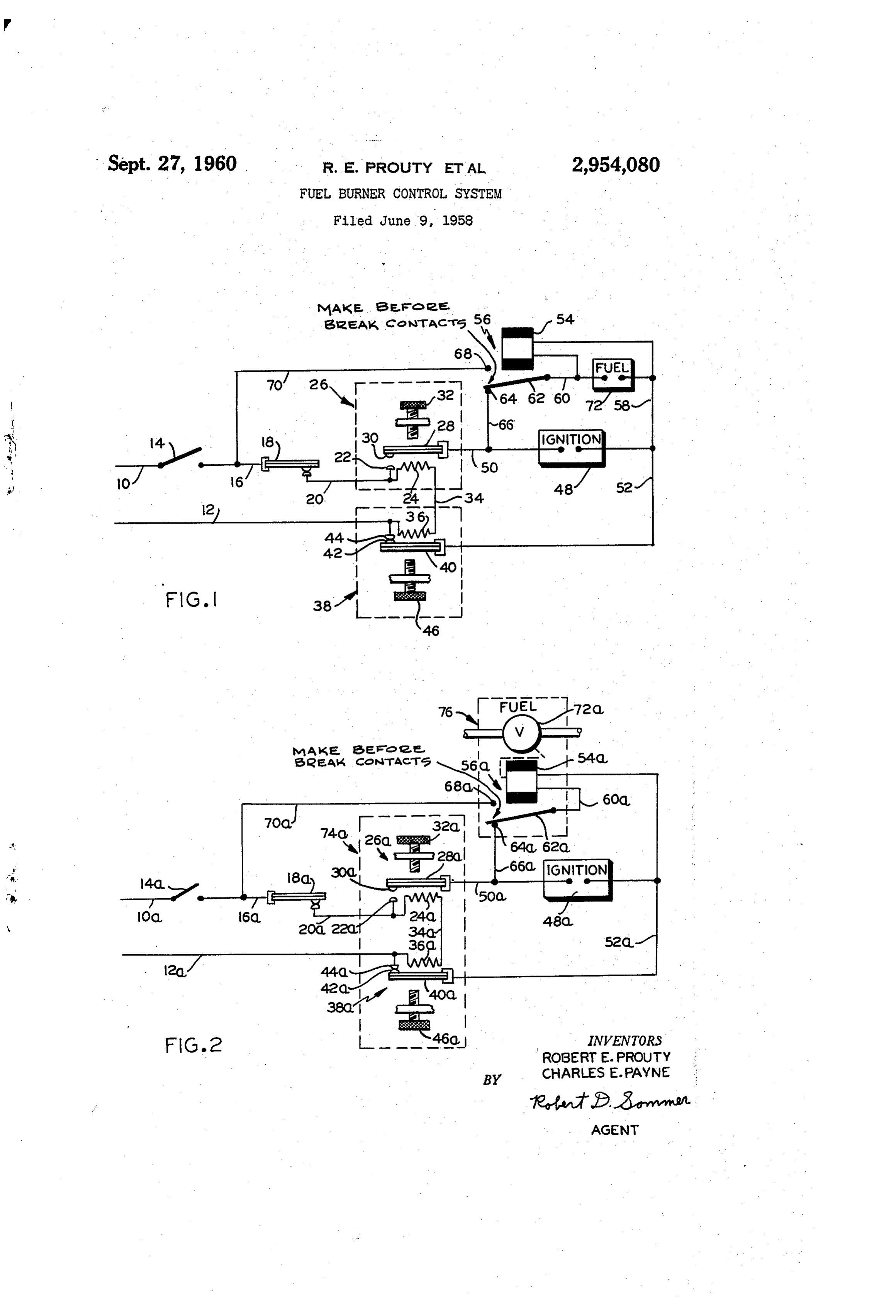
Figure 1 is a schematic diagram of a safety control system for a fuel burner embodying the invention; and
Figure 2 is a schematic diagram of a modified form of control system embodying the invention.
Referring now more particularly to Figure 1 of the drawing, there is shown a control system for a fuel burner including the supply conductors 10 and 12. The supply conductor 10 connects to a switch 14 which controls the flow of current to the entire circuit of the control system. Switch 14 may be a master switch or a condition respon-
"sive switch such as a thermostat. Switch 14 is connected
by conductor 16 to a combustion responsive switch 18 which is responsive to temperatures caused by operation of the fuel burner. Switch 18 is in its closed position in the absence of combustion and in its open position in the presence of combustion.
Switch 18 is connected by conductor 20 to the stationary contact 22 and the heating element 24 of a thermally operated time delay switch 26. The heating element 24 is adapted to heat the bimetal 28 which carries at its end a contact 30 adapted to make contact with contact 22 when bimetal 28 is heated. An external adjusting screw 32 is provided to act on bimetal 28 for adjusting time delay switch 26 to obtain the desired time delay.
Heating element 24 is connected by conductor 34 to the heating element 36 of a thermally operated time delay switch 38. The heating element 36 is adapted to heat the bimetal 46 which carries at its end*a contact 42 adapted to make contact with stationary contact 44 exexcept when bimetal 40 is heated. Contact 44 is connected to the heating element 36 at its connection with the supply conductor 12. An external adjusting screw 46 is provided to act on bimetal 40 for adjusting time delay switch 38 to obtain the desired time delay.
An ignition device 48 for igniting fuel supplied to the burner is connected between bimetals 28 and 48 by conductors 56 and 52, The operating winding 54 of a control relay 56 has one end connected to bimetal 40 through conductors 58 and 52. The other end of operating winding 54 is connected to bimetal 28 through conductor 60, movable contact 62 of control relay 56, normally closed stationary contact 64 of control relay 56, conductor 66, and conductor 58. Contro} relay 56 includes a normally open stationary contact contact 68 cooperating with movable contact 62 and connected by conductor 70 to switch 14 at its connection with switch 18. Upon energization of operating winding 54, movable contact 62 engages contact 68 before it separates from contact 64. Connected in parallel with the operating winding 54 of control relay 56 is a fuel delivery device 72 for controlling the flow of fuel to the burner. Fuel delivery device 72 must be energized for delivery of fuel to the burner and may take the form cf an electromagnetic valve cr a motoroperated pump.
When heat is required, switch 14 is closed to energize heating elements 24 and 36 through the following circuit: supply conductor 10, switch 14, conductor 16, combustion responsive switch 18, conductor 2@, heating element 24, conductor 34, heating element 36, and supply conductor 12. Heating element 24 has a greater resistance than heating element 36 and bimetal 28 will close its contacts 22 and 30 in a relatively short period of time such as six seconds while bimetal 36 must be heated for a longer period of time such as fifteen seconds before it separates contacts 42 and 44. Upon contact 30 engaging contact 22, the ignition device 48 is energized through the following circuit: supply conductor 10, switch 14, conductor 16, combustion responsive switch 18, conductor 20, contact 22, contact 39, bimetal 28, conductor 50, ignition device 48, conductor 52, bimetal 40, contact 42, contact 44, and supply conductor 12. At the same time operating winding 54 of control relay 56 is energized through the following circuit shunting ignition device 48: conductor 66, contact 64, contact 62, conductor 66, operating winding 54, and conductor 58. When relay 56 operates, the energizing circuit for operating winding 54 through the stationary contact 64, time delay relay 26, and combustion responsive switch 18 is interrupted and replaced by an alternative circuit including stationary contact 68 and conductor 70. As the fuel delivery device 72 is connected in parallel with operating winding
Page 3
54, fuel is supplied to the burner for ignition by the ignition device 48 whenever winding 54 is energized.
If combustion of the fuel at the burner occurs in a normal manner to cause the combustion responsive switch 18 to open in a short interval of time, the ignition device 48 and the heating elements 24 and 36 will be deenergized.: Delivery, of fuel to the burner will continue because bimetal 40 was not heated sufficiently by heating element 36 to separate contacts 42 and 44. The bimetals 28 and 46 will cool and contacts 22 and 3% will re-open.
Upon opening of switch 14 when the heat requirements have been fulfilled by the burner or in the event of an electrical power interruption, the entire circuit is deenergized. The movable contact 62 of rélay 56 separates from the normally open contact 68 and the fuel delivery device 72 cannot be energized except concurrently with the ignition device 48 after the combustion responsive switch 18 has returned to its closed position.
if for any reason energization of the ignition device 48 and the fuel delivery device 72 does not result. in combustion of the fuel, the combustion responsive switch 18 remains closed continuing energization of heating elements 24 and 36. In a short interval after engagement of contacts 22 and 39, bimetal 40 causes contacts 42 and 44 to separate and deenergize both the ignition device 48 and the fuel delivery device 72. Contacts 42 and 44 will remain separated as long as the switch 14 remains closed.
Should combustion fail during operation of the burner, combustion responsive switch 18 will reclose again energizing the ignition device 48 and the fuel delivery device 72. If combustion is not reestablished, contacts 42 and 44 of time delay relay 38 will separate to interrupt the circuit to the ignition device 48 and the fuel delivery
' device 72 as described above.
It will be apparent that the circuit of the control system is so arranged that the control system will fail safely if the operating winding 54 of relay 56 or either of the heating elements 24 and 26 should burn out. Furthermore, it will be noted that the burner can not be placed in operation upon failure of the heat responsive switch 18. If switch 18 should remain closed in the presence of combustion, heating element 36 remains energized and will cause bimetal 46 to separate contacts 42 and 44 which deenergizes the fuel delivery device 72. If switch 18 should remain open in the absence of combustion, it is not possible to energize the fuel delivery device 72.
Figure 2 shows a modified form of control system similar to that of Figure 1 and to which reference numerals corresponding to those used in Figure 1 with the letter a added have been applied to corresponding parts. The system of Figure 2 differs from that of Figure 1 in that time delay relays 26a and 38a are combined in a single unit designated by reference numeral 74 while fuel delivery device 72a takes the form of a valve actuated by the operating winding 54a of control relay 56a. The combined control relay and fuel delivery device is designated by reference numeral 76 and may be constructed in a well-known manrier. It. will be obvious that the control system of Figure 2. operates in the same manner described for the control system of Figure 1.
While the invention has been illustrated and described in preferred embodiments and has included certain details, it should be undérstood that the invention is not to be limited to the precise details herein illustrated and described since the same may be carried out in other ways falling within the scope of the invention as claimed.
What is claimed is:
1. A control system for a fuel burner having fuel delivery means for controlling the supply of fuel to the
. burner and ignition means for igniting fuel supplied to the burner, said control system comprising: a first time delay relay having a normally open switch, a bimetal member for closing the normally. open switch when heated, and an electric heating element for heating the
bimetal member; a second time delay relay having a normally closed switch, a bimetal member for opening the normally closed switch when heated, and an electric heating element for heating the bimetal member of the second time delay relay; a control relay having an operating winding, a normally closed switch opened upon energization of the operating winding, and a normally open switch closed upon enérgization of the operating winding; a combustion responsive switch adapted to open and close in response to the presence and absence of combustion at the burner; a first circuit adapted for connection to a source of electric power and including in series connection the combustion résponsive switch and the heating elements of the first and second time delay relays; a second circuit adapted for connection to the source of electric power and including in series connection the combustion responsive switch, the ‘normally open switch of the first time delay relay, the ignition means, and the normally closed switch of the second time delay relay; first circuit means connecting the operating winding of the control relay to the source of electric power through the normally closed switch of the second time delay relay, the normally closed switch of the control relay, the normally open switch of the first time delay relay, and the combustion responsive switch; second circuit means connecting the operating winding of the control relay to the source of electric power through the normally closed switch of the second time delay relay and the normally open switch of the control relay; means rendering the fuel delivery means operative to deliver fuel to the burner when the operating wind ing of the control relay is energized from said source of electric power; the normally open switch of the first time delay relay closing after a first predetermined time period of energization of its heating element; and the normally closed switch of the second time delay relay being adapted to open after a second longer predetermined time period of energization of its heating element.
2. The control system defined in claim 1 wherein said fuel delivery means comprises a fuel valve actuated by said operating winding of the control relay.
3. A control system for a fuel burner having fuel delivery means for controlling the supply of fuel to the burner and ignition means for igniting fuel supplied to the burner, said control system comprising: a first normally open timer switch and a second normally closed timer switch; electrically energizable actuating means for the timer switches; the first timer | switch p being acuated
time period; the second timer switch being actuated from a closed to an open condition after energization of the timer actuating means for a predetermined time period longer than said first time petiod; an electromagnetic actuator; switching means controlled by the electromagnetic actuator and including a first normally closed switch opened upon energization of the actuator and a second normally open switch closed upon energization of the actuator; means rendering the fuel delivery means operative to deliver fuel to the burner upon energization of the eléctromagnetic actuator; a cormbustion-responsive switch closed in the absence of combustion at the burner and open in the presence of combustion at the burner; a first circuit including the combustion-responsive switch and the timer actuating means connected in series; a second circuit including the combustion-responsive switch, the first timer switch, the ignition means and the second timer switch connected in series; a third circuit including the combustion-responsive switch, the first timer switch, the first electromagnetic actuator switch, the electromagnetic actuator and the second timer switch connected in series; a fourth circuit including the second electro- Magnetic actuator switch, the electromagnetic acttator and the second timer switch connected in series; and
Page 4
means for connecting the first, second, third and fourth circuits to an electric power source.
4, The control system defined in claim 3 wherein the actuating means for the timer switches comprise a heatsensitive actuating element for each timer switch and an electrical heater for each actuating element, the electrical heaters being connected in series.
References Cited in the file of this patent
UNITED STATES PATENTS
Provenance
- Collection
- Cited prior art
- Original assignee
- Essex Wire Corp
- Original PDF
- patentimages.storage.googleapis.com →
- Filed
- 1958-06-09
- Pages
- 4
- Method
- pdftoppm 300dpi + tesseract 5 (eng)
- Source
- Google Patents bibliographic record
- Granted
- 1960-09-27
- Inventors
- Robert E Prouty; Charles E Payne; Essex Wire Corp
- Transcribed from
- patentimages.storage.googleapis.com →