patent · US2812806
Electrically controlled safety igniter circuit for gas burners
12 November 1957
Page 1
Drawing sheet — no readable text.
Page 2
United States Patent Office M 2,812,806 Patented Nov. 12, 1957
123,018, filed on October 22, 1949 by Peter E. Geldhof and Harold E. Morrison, and entitled “Gas Heated 2,812,806 Drier' and now Patent No. 2,635,354, dated April 21,
ELECTRICALLY CONTROLLED SAFETY IGNITER 5 1953 so the drier and the circuit therefor, need only be (CIRCUT FOR GASBURNERS described herein in sufficient detail to make my present invention readily understandable.
Harold E. Morrison, assignments, St. Joseph,Corporation, to Whirlpool Mich., assignor, by mesne a corporation A gas supply line 10 is shown as delivering gas to a of Delaware master gas supply valve 1 operated to open upon ener gization 10. the of a coil 12 of a solenoid. A pipe 13 connects
Application February 9, 1953, Serial No. 335,646 master valve 11 with a main burner valve 15 con 6. Claims. (C. 158-124) trolling the supply of gas to a main burner 16. A pilot burner 17 leads from the supply side of the main burner valve 15 to a position adjacent the burner 16, for igniting
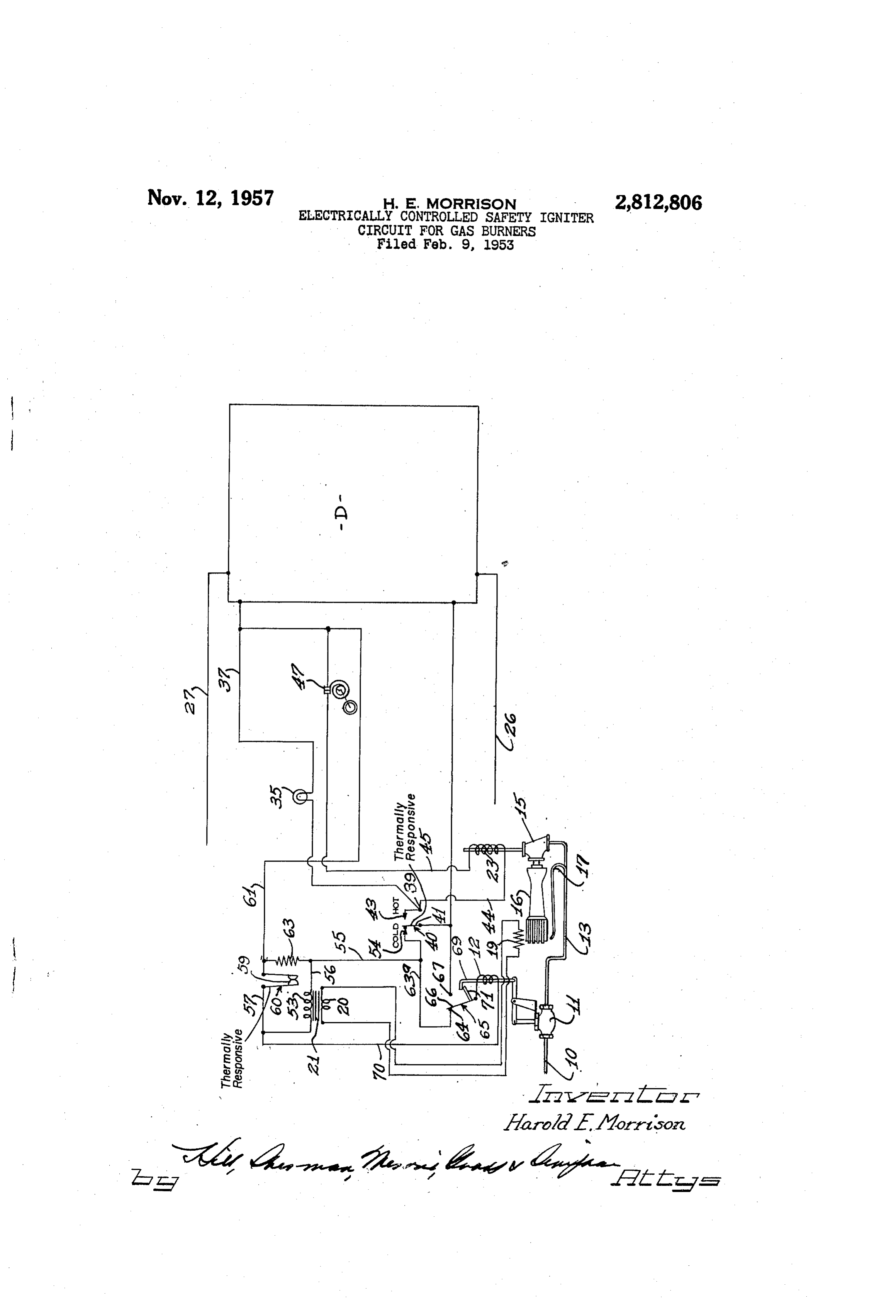
This invention relates to improvements in automatic 5 burnersaid burner when the valve 15 is turned on. The pilot igniter circuits for gas burners and more particularly re supplied17withis controlled by the master valve 11 and is gas when the valve 11 is open. The pilot lates to an electrically controlled safety igniter circuit for burner 17 is shown as being ignited by a glow coil 19 gas burners. energized by the secondary 20 of a transformer 21. A principal object of my invention is to provide a safety igniter circuit for gas burners, operated and con theWhile I have herein shown a glow coil for igniting trolled by an electrical circuit so arranged as to instan coil need not be 17, pilot burner it should be understood that a glow taneously close the gas supply and prevent unburned gas the pilot may be ignited by to employed ignite said pilot, but that an interrupted spark type of from passing through the main burner upon interruption igniter or by any other suitable igniting means and may of the electric circuit.
A further object of my invention is to provide an auto 25 even be ignited by hand if desired. The glow coil 19 is positioned adjacent the pilot 17, but for convenience in matic gas igniter circuit in which a master valve is opened illustrating the control circuit, is shown as being remote through the cold contact of a flame detector Switch and from said pilot. The main burner valve 15 is shown as a main burner valve is opened through the hot contact being Solenoid operated, and as opening upon the ener of the fame detector switch, having an electrical inter 30, gization of a coil 23 of the solenoid therefor. lock preventing opening of the master valve upon a power interruption except through the cold contact of the flame of The valves 11 and 15 may be of any well known form Solenoid operated gas control valve, one form of valve detector switch. construction being illustrated in my joint application with A further object of my invention is to provide a Peter E. Geldhof, simplified and novel form of control for an automatic gas 35. No. 2,635,354, datedSerial No. 123,018 and now Patent pilot so arranged as to render it impossible to supply gas The structure of said valves 21, April
1953 referred to before.
no part of my present in to the main burner when the pilot is out. vention so need not herein be shown or described in de Still another object of my invention is to provide an tail.
automatic igniter for gas burners having an electrical in The Supply of electric power to the operative com terlock for the master valve in the gas supply line, main 40 ponents of the clothes drier shown as being enclosed in taining the valve closed upon power interruption until a diagrammatic box D is effected through a pair of con the system is sufficiently cool to safely turn on the gas. ductors 26 and 27.
Still another object of my invention is to provide an igniter circuit for a main gas burner including a flame in An the indicator light 35 is also shown as being connected circuit through a terminal 39 of a flame detector detector switch having hot and cold contacts connected 45 Switch 40, and lighting when a contact arm 41 of the to initially turn on a master burner valve when the flame flame detector Switch moves into position to complete a detector switch is in its cold position, and to hold the circuit through a contact 43 of said switch, which is main burner valve out of the circuit until the pilot burnex hereinafter referred to as the hot contact thereof. The has been ignited, and including a shut-off switch con indicator light 35 thus indicates when the main burner nected in the energizing circuit for the burner valves, valve is on.
biased to energize the solenoid for a master gas supply 50 A conductor 44 leads from the contact 43 of the flame valve through the cold contacts of the flame detector detecting switch 40 and is connected with the coil 23 of switch and movable to connect the solenoid of the master the Solenoid for operating the main burner valve 15. A gas supply valve to by-pass the flame detector switch conductor 45 connects said coil to the contact 36 of the upon opening of said valve, and locking the master gas 55 timer Switch 34. An adjustable thermostat 47, which may supply valve from opening when the supply of power be manually set to control the drier temperature is con has been interrupted and is again turned on, except nected in the conductor 45 to break the circuit there through the cold contacts of the flame detector switch. through and shut off the main burner valve when the These and other objects of my invention will appear temperature within the drier drum reaches the tempera from time to time as the following specification proceeds 60 ture for which said adjustable thermostat is set. and with reference to the accompanying drawing which A primary coil 53 of the transformer 21 is initially diagrammatically shows an automatic igniter circuit con connected in the energizing circuit through the conduc structed in accordance with my invention. tor 51 and a contact 54 of the flame detecting switch 40. In the embodiment of my invention illustrated in the The connection from the cold contact. 54 includes a con drawing, the igniter safety circuit of my invention is shown ductor 55 leading from said cold contact and having a as being operative to ignite and control the operation of conductor 56 connected thereto which in turn is con the master valve and main burner valve of a clothes nected to one terminal of the coil 53. The other ter I drier, although it need not be in such a circuit and may minal of the coil 53 is connected with the conductor 27 be utilized to ignite various types of gas burners used for through a conductor 57, contacts 59 of a warp switch various purposes. 70 60 and a conductor 61, connected to the conductor 37. The control circuit for the drier is somewhat similar A heater coil 63 is shown as being connected in parallel to that shown and described in application Serial No, with the primary 53 of the transformer 21 and as being
Page 3
energized upon the energizing of said primary, to open This will energize the coil 23 and open the main burner the contacts of the warp switch 59 by resistor heat after valve 15. Thus when the pilot burner 17 has been ignited a predetermined time interval, which may be from 3 to 5 the main burner valve 16 can only open when the heat of minutes at normal voltages. the flame has moved the contact arm 41 into eigage The coil 12 of the solenoid for opening the master ment with the hot contact 43.
valve 1 is shown as being energized through the cold The instant, however, a power interruption occurs, the contact 54 of the flame detector switch 40 by a conductor coils 23 and 12 will be de-energized. This will shut off 63a, connected with a contact 64 of a shut-off switch 65. the master valve 11 and the supply of gas to the pilot The shut-off switch 65 may be a well known form of burner 17 and the main burner valve 5. It will also quick acting shut-off switch having a contact arm 66 10 shut off the main burner valve 15. De-energizing of the normally biased to complete a circuit from the contact coi! 2 will also release the quick shut-off Switch 65. 64 to the coil 12. The quick shut-off switch 65 is shown Said switch will then move to its biased position to com as being moved to complete a circuit through a contact plete a circuit through the contact 64 and cold contact 67 connected with the conductor 51 by operation of an 54 of the flame detecting switch 40 to the coil 12. When armature 69 for the solenoid operating the valve 11, the quick shut-off switch 65 is in the position just men." upon the energization of the coil 12 and opening of the tioned, the coil 12 can only be energized through the master valve 11. Thus when the fiame detector switch cold contact 54 of the flame detecting Switch 48. 40 is in position to complete a circuit through its con The main or master supply valve, therefore, cannot be tact arm 43 and cold contact 54, the coil 12 will be ener opened to supply gas to the pilot i7 and main burner gized. This will immediately break the circuit through 20 15 until the main and pilot burners have cooled sufficient the contact 64 and complete a circuit to a contact 67, ly to accommodate the contact arm 41 to move from its holding said coil energized through the conductor 51. hot to its cold position.
The circuit from the coil 12 to conductors 61 and 27 is In operation, the contacts 59 of the warp switch 60 shown as comprising a conductor 70 connected with the are normally closed and the movable contact 41 is en conductor 57, the contacts 59 of the warp switch 60 25 gaged with the cold contact 54. When the switch 34 when said warp switch is in a closed position, and the and the door switch 29 have been closed, the solenoid timer switch 34. - coil 12, the transformer primary 53, and the coil 63 of The warp switch 60 is provided to deenergize the coil the timed delay or warp switch 60 will all be connected 12 for the solenoid of the master supply valve 1i and in parallel between the supply lines 27 and 51. The shut off the supply of gas to the pilot burner 17 and main 30 master gas supply valve 11 will then be opened and gas burner valve 15 in the event the flame detector switch will be supplied to the pilot burner 17. Upon opening should not pass from its hot to its cold position, as when of the master gas supply valve 11, the switch arm 66 of the pilot burner should not be ignited after a predeter the quick shut-off switch 65 will move into engagement mined time interval, or if the pilot should go out before with the contact 67 and hold the solenoid energized the main burner is lit. 35 through the conductor 51. In normal operation the gas The contacts of the warp switch 60 are normally closed. issuing from the pilot burner 17 will be ignited by the The heater coil 63 is provided to open the contacts of glow coil 19 and the heat of the pilot burner flame will said warp switch by resistor heat in a time interval which move the movable contact arm 41 of the flame detecting may be from three to five minutes should the switch switch 40 out of engagement with the cold contact 54 into arm 41 fail to move out of engagement with the cold 40 engagement with the hot contact 43 of said flame detecting contact 54 into engagement with the hot contact 43, switch. The solenoid coil 23 of the main burner valve as by failure of the pilot to ignite, as previously men 15 will then be energized through the hot contact 43 tioned. Upon opening of the circuit through the con connected with the conductor 5 through the contact arm tacts 59 of the warp switch 60 by resistor heat, the con 41, the conductor 45, the thermostat 47, the switch 34 ductor 55, cold contact 54 and contact arm 4 of the flame 45 and conductor 27. The main burner valve 15 will then detector switch 40 will short circuit the coil 12 from the open to supply gas to the main burner 16. energizing circuit and the main or master burner 11 will If, for any reason, the pilot burner should fail to ignite, go off by de-energization of the coil 12. When this the heater coil 63 of the time-delay or warp switch 60 occurs, the armature 69 of the solenoid operating said will open its contact 59 after a predetermined time inter master burner valve will release an arm 7 of the quick 50 val. When this occurs, the solenoid coil 12 as well as the shut-off switch 65 and said switch will move to its primary 53 of the transformer 21 will be de-energized and biased position and complete a circuit through the con the contacts 59 will be maintained in open position. tact 64 and contact arm 66 thereof. When the quick The quick shut-off switch 65 will also be released, and shut-off switch 65 is in this position, the coil 12 can only the contact arm 66 thereof will move to its biased posi be energized and the master valve 11 can only be open 55 tion into engagement with the contact 64. The solenoid when the flame detector switch 40 is in position to com coil 12 thereof cannot again be energized until the con plete a circuit through its contact arm 44 and cold con tact arm 41 has moved into position to engage the cold tact 54. contact 54, and the contacts 59 of the warp switch 60 - In order to ignite the pilot burner 17 and the main have been closed. In order to again ignite the burner, the burner 16 when the solenoid 12 has been de-energized by 60 switch 34 must be opened to allow the time-delay or warp failure of the pilot burner to ignite and the contacts 59 switch 60 to cool and close a circuit through the con I of the warp switch are maintained open by the heater tacts 59 thereof. The switch 34 may then be closed. coil 63, the circuit to the dryer must be opened as by The solenoid coil 12 may then be energized, opening opening of the switch 34, to allow the time-delay warp the main burner 11 and engaging the contact arm 65 with switch 60 to cool and close the contacts 59, after which the contact 67 to maintain the solenoid coil 12 energized - the switch 34 may again be closed and the burner circuit and the main burner valve 11 open. The main burner is in condition to ignite the pilot burner. will then be ignited and the circuit will be re-established, The flame detector switch 40 may be of a type similar as previously described.
to that shown and disclosed in my joint application with It may be seen from the foregoing that a simplified P. E. Geldhof, Serial No. 123,018 and now Patent No. 70 igniter circuit for gas burners has been provided, in 2,635,354, dated April 21, 1953 previously mentioned, Stantaneously shutting off the supply of gas to the main wherein the heat of the pilot flame will move the con burner upon a power failure and holding the supply of tact arm 41 into position to close a circuit through the gas shut off until the flame detecting switch has passed to hot contact 43 of said switch and complete a circuit position to close a circuit through its cold contacts and from the conductor 51 to the conductors 45 and 27. 75 turning on the supply of gas to the pilot burner only
Page 4
through the cold contacts of the flame detecting switch, said pilot burner to ignite, and the energizing circuit to and holding the main burner valve closed until the pilot said solenoid for said master valve also including a shut burner has been ignited a sufficient length of time to off switch having two contacts, one connecting said sole move the contact arm of the flame detector switch 40 to noid coil with the cold contacts of flame detector switch engage the contact 43, thereof and complete a circuit and the other being connected directly in the energizing through the hot contacts of said switch. circuit and connecting said solenoid coil for said master It will be understood that various modifications and valve in the energizing circuit upon the energization of variations of the present invention may be effected without said solenoid coil, said shut-off switch being biased to hold departing from the spirit and scope of the novel concepts said solenoid for said master valve out of the energizing thereof. O circuit except through the cold contacts of said flame de I claim as my invention: tecting Switch whenever a power interruption occurs. 1. A gas burner circuit comprising a main gas burner 4. In a gas burner circuit, a main gas supply line, two having a gas Supply line connected thereto, master and valves connected in series in said gas supply line, one main burner Solenoid opearted valves in said supply line, being a master valve and the other being a main burner a flame detector Switch having hot and cold contacts, an 5 valve and being connected in said gas supply line. on the energizing circuit to the solenoid of said master valve downstream side of said master valve, a pilot burner through the cold contact of said flame detector switch, connected in said gas supply line on the downstream side an energizing circuit to the solenoid of said main burner of said master valve and the supply side of said main valve through the hot contact of said flame detector burner valve, individual solenoids for each of said Switch, a main line energizing circuit connected with 20 valves, energizable to open said valves, a main line con said flame detector switch, and the circuit from the cold ductor and a flame detector switch connected with said contact of said flame detector switch including a shut-off main line conductor and having hot and cold contacts Switch, biased to complete a circuit to the solenoid for and a movable. Switch arm movable from a position in said master valve through the cold contact of said flame engagement with said cold contact into engagement with detector Switch and operated upon energization of said 25 said hot contact to complete a circuit from said main line Solenoid for said master valve, to break the circuit through conductor through said hot contact to energize said sole Said cold contact and connect said solenoid for said master noid for said main burner valve upon the presence of a valve directly to said main line energizing circuit until a pilot flame, a shut-off switch connected in series with the power interruption, and moving to its biased position cold contact of said flame detector switch for initially upon a power interruption and holding said solenoid for 30 energizing said solenoid for said master valve through Said master valve out of the energizing circuit except the cold contact of said flame detector switch, said shut through the cold contact of said flame detector switch. off switch having two contacts, one being connected with 2. A gas burner circuit comprising a main gas burner the cold contact of said flame detector switch and the having a gas supply line connected thereto, a master other being connected directly with said main line con Solenoid-operated valve in said supply line, a main burner ductor, said shut-off switch being biased to close a circuit Solenoid-operated valve in said supply line, a pilot burner through the cold contact of said flame detector switch in Said supply line on the supply side of said main and moved by the opening of said master valve upon en burner valve, a flame detector switch having hot and cold ergization of the solenoid therefor to open the energizing contacts and moving from a position closing a circuit circuit to said master valve through the cold contact of from a main line circuit through its cold contact to a 40 said flame detector switch and to maintain a holding cir position closing a circuit from the main line circuit through cuit for the solenoid for said master valve through said its hot contact by the presence of a pilot flame, an energiz main line conductor, said shut-off switch moving back to ing circuit to the solenoid of said master valve through its biased position and deemergizing said solenoid for said the cold contact of said flame detector switch, an energiz master valve upon an interruption in the energizing cir ing circuit to the solenoid of said burner valve through cuit, and holding said solenoid for said master valve de the hot contact of said flame detector switch, and the energized and maintaining said master valve closed until energizing circuit to said solenoid for said master valve movement of said flame detecting switch into position including a shut-off switch biased to complete a circuit to close a circuit through its cold contact. to said Solenoid through the cold contact of said flame 5. In a gas burner circuit, a gas supply line, two valves detector Switch and moved by opening of said master 50 connected in series in said gas supply line, one being a valve to by-pass said cold contact and connect said master valve and the other being a main burner valve, solenoid for said master valve directly with the main the master valve being on the supply side of said main line circuit upon energization of said solenoid for said burner valve and having a pilot burner connected there master valve, and moving back to its biased position with for igniting a main burner, individual solenoids for upon a power interruption. each of said valves energizable to open the same, a flame 3. In an automatic gas igniter, a gas supply line hav detector switch having hot and cold contacts and a mov ing a main burner valve therein and a master valve on the able switch arm engageable with the cold contact when supply side of said main burner valve, for controlling the the pilot is not lit and movable into engagement with the Supply of gas to said main burner valve, a pilot burner on. hot contact to close a circuit therethrough by the heat the Supply side of said main burner valve and the down 60 of a pilot flame, a main line conductor connected with stream side of said master valve, individual solenoids said movable switch arm, an energizing circuit from said for each of said valves energizable to open the same, an main line conductor to said solenoid for said master valve energizing circuit for said solenoids including a flame de through said flame detector switch, the energizing cir tector Switch having hot and cold contacts, the hot con cuit to said solenoid for said master valve including a tacts of said flame detector switch being connected to quick shut-off switch operated by actuation of said master energize the Solenoid for said main burner valve, a warp valve and having two contacts and a contact arm con switch having contacts connected in series with the sole nected with said Solenoid for said master valve, one of noid coil for said master valve to energize said coil when said contacts being electrically connected with the cold the contacts of said warp switch are closed and said contact of said flame detector switch to energize said flame detector switch is in position to close the circuit 70 solenoid for said master valve through the cold contact of through its cold contacts, a heater coil energized through said flame detector switch, the other of said contacts being the cold contacts of said flame detector switch and open connected directly with said main line conductor to en ing said warp switch by resistor heat, to shunt said sole ergize said solenoid for said master valve directly through noid coil for said master valve out of the energizing cir said main line conductor upon movement of said master cuit and shut off the Supply of gas upon the failure of 75 valve to an open position upon energization of the solenoid
Page 5
therefor, and means biasing said contact arm of Said shut with said inlet valve actuator, said double throw switch off switch into engagement with said one contact to close being biased to one position and being moved to its op a circuit through the cold contact of said flame detector posite position by said inlet valve actuator when it is switch upon a power interruption and the deemergization energized, an energizing circuit for said inlet valve actuator of the solenoid for said master valve. including said double throw switch when in its biased 6. In a burner control system in combination, a pilot position and said flame sensitive switch when in its cold burner, a fuel control means having in serial connection position, an energizing circuit for said igniter including with one another a normally closed inlet valve, a nor said flame sensitive switch when in its cold position, an mally closed outlet valve, and a main burner fuel Supply energizing circuit for said outlet valve actuator including outlet, said fuel control means further including an outlet 10 said flame sensitive switch when in a hot position, and between said inlet and outlet valves for Supplying fuel shunt means for maintaining an energizing circuit for said to said pilot burner, whereby said inlet valve controls inlet valve actuator when said flame sensitive switch moves the flow of fuel to both burners and said outlet valve from said cold to said hot position including said double controls the flow of fuel to the main burner only when throw switch when in its opposite position. said inlet valve is open, an electromagnetic actuator for 5 said inlet valve, an electromagnetic actuator for said outlet References Cited in the file of this patent valve, an electrically operated igniter for said pilot burner, a flame sensitive switching device having a normally cold 2,269,157 position and being responsive to move from said cold 20 2,327,690
UNITED STATES PATENTS
position to a hot position in response to a flame at said 2,456,147 Ray ------------------ Dec. 14, 1948 pilot burner, a double throw switch operatively associated
Provenance
- Collection
- Cited prior art
- Original PDF
- patentimages.storage.googleapis.com →
- Filed
- 1953-02-09
- Pages
- 5
- Method
- pdftotext (the PDF's own text layer) + pdftoppm 300dpi page scans
- Source
- Google Patents bibliographic record
- Granted
- 1957-11-12
- Inventors
- Harold E Morrison; Whirlpool Corp
- Transcribed from
- patentimages.storage.googleapis.com →