patent · US2449858
Burner safety control system
21 September 1948
Page 1
Drawing sheet — no readable text.
Page 2
Patented Sept. 21, 1948 2,449,858
UNITED STATES PATENT OFFICE
BURNER SAFETY CONTROL SYSTEM
Jerome Ottmar, Attleboro, Mass., assignor to
Metals & Controls Corporation, Attleboro,
Mass, a corporation of Massachusetts
Application April 21, 1945, serial No. 589,567
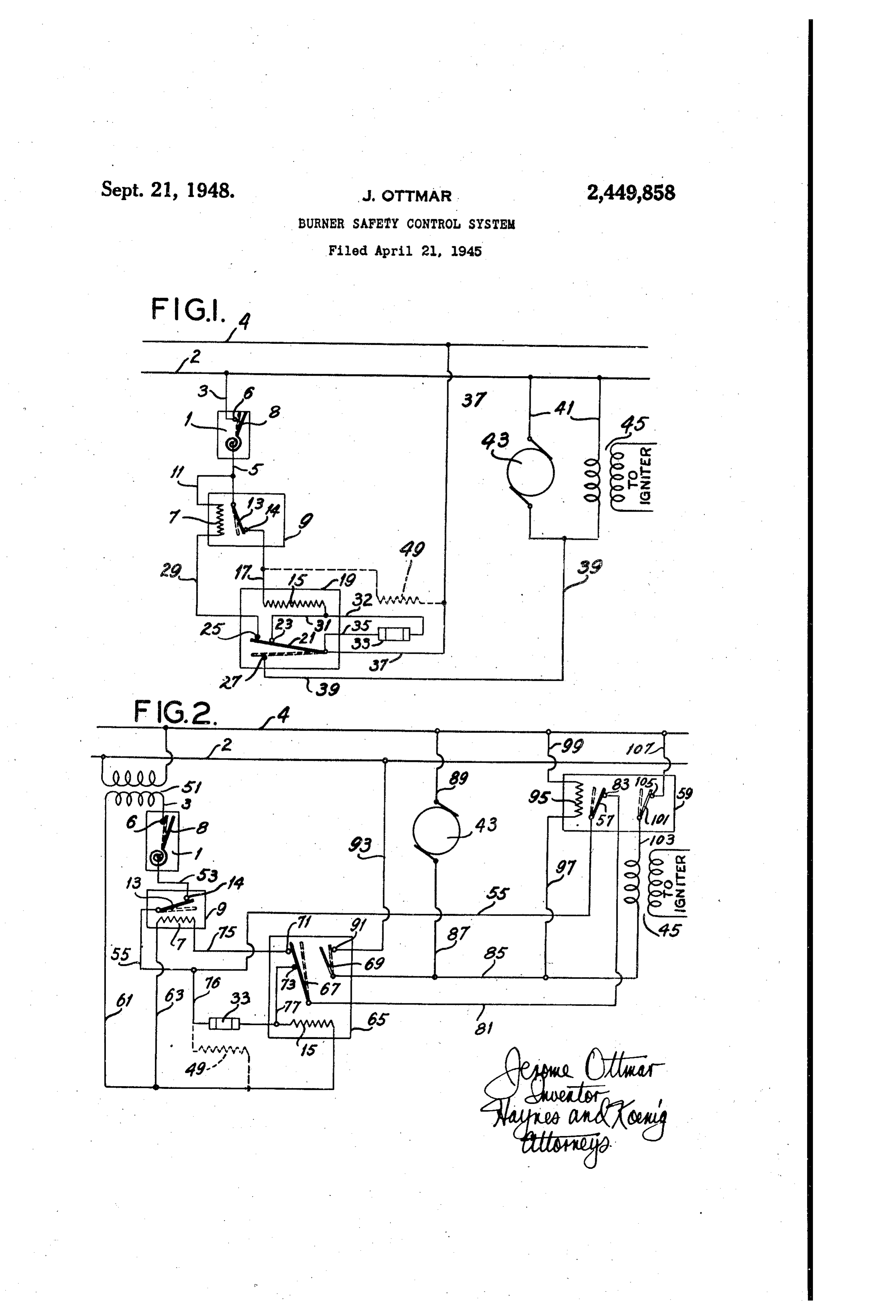
This invention relates to control circuits and 5 is the thermostatic control element 3 of a ther more particularly to control circuits for burners. mal relay safety switch 9. Thermal element 3 Among the objects of the invention may be cooperates with a contact 4 when the former noted the provision of control circuits which is in its solid line position, but does not meet Control a burner without the necessity for sub contact 4 when it is in another position assumed jecting a thermostatic control member to the in response to temperature change. A heater burner temperature; a control circuit which does 7, for thermostatic element 3, is connected to not utilize a magnetic relay; a control circuit wire 5 by wire f. Safety switch. A may be of the which provides a safety shut-down by the oper construction shown in Bolesky Patent 2,199,388 ation of a unit which also acts as the control O and is preferably of the manual reset type. relay; a control circuit in which it is not neces Contact 4 is connected by a wire to the Sary to re-cycle over the entire series of oper heater 5 of a thermostatic time-delay relay f. ations in all instances, so that it is not nec Relay 9 is preferably of the type described in essary in all events to await the passage of an Wilson Patent 2,203,558, in which an ambient entire Scavenger period; a control circuit in which 15 compensated control member operates a switch the safety shut-down timing is controlled by the bar. Heater 5 is connected at its opposite side off-time rather than by the on cycle; a burner by wire 3 to a contact 23. A switch bar 2 coop Control System which has few and inexpensive erates with contact 23 in one position of the parts which may require replacement and which thermostatic elements of relay 9. are readily accessible for repair and replacement; 20 Heater is connected at its opposite side by a and, the provision of a control circuit in which wire 29 to a contact 25 which also cooperates the timing is only slightly affected by voltage with switch bar 2 when the latter is in its solid variations. Other objects will be in part apparent line position. When the thermostatic control and in part pointed out hereinafter, elements of relay 9 snap to their other position The invention accordingly comprises the ele 25 in response to temperature change, they move ments and combinations of elements, features . Switch bar 2 from its solid line position to its of Construction, and arrangements of parts which dotted line position, thereby separating bar 2 Will be exemplified in the structures hereinafter and contacts 23 and 25, and bringing bar 2 and described, and the Scope of the application of contact 27 together. .
Which will be indicated in the following claims. 30 Switch bar 2 is connected by a wire 37 to In the accompanying drawing in which are ill power line 4 and by a wire 35 to a flame-sensitive lustrated Several of various possible embodiments current controller 33, preferably of the type dis of the invention, closed in Hower Patent 2,106,249. Current con Fig. 1 is a wiring diagram of a burner system; troller 33 is connected to heater 5 by a wire 32. and, Contact 27 is connected by a wire 39 to a parallel Fig. 2 is a Wiring diagram of an alternative circuit which includes the motor 43 of an oil embodiment. burner pump, and the igniter 45 for said oil Similar reference characters indicate corre burner. Parallel circuit 4 is connected to power Sponding parts throughout the several views of line 2.
the drawing. 40 The thermostatic element 8 of thermostatic In the interest of simplicity the present in switch is shown in solid lines out of contact vention will be described as applied to the con With contact 6. When, upon change of tempera trol of oil burners. It will be understood, how ture, thermostatic element 8 moves to its dotted ever, that the control circuits of the present in line position thereby meeting contact 6, a circuit vention are equally applicable to the control of 45 is closed from power line 2 to wire 3, contact 6, Other burners, such as gas burners, coal burners, thermostatic element 8, wire 5, thermostatic ele citc. ment 3, contact 4, wire 7, heater 5, wire 3, Referring now to Fig. 1 of the drawing, main contact 23, switch bar 2, and wire 37 to power power lines 2 and 4 provide a source of power. line 4. A parallel circuit is likewise closed from Connected to power line 2 by a wire 3 is a contact 50 wire 5 to wire , heater , wire 29 and contact 6 of a main thermostatic control SWitch , of the 25 to switch bar 2.
type usually employed in the area to be heated by Current then passes through heaters 7 and 5 the burner. Such a control includes, in addition until heater 5 has transmitted sufficient heat to contact 6, a thermally responsive member 8. to the thermostatic elements of relay 9 to cause Connected to thermostatic member 8 by a wire 55 these thermostatic elements to snap to their op
Page 3
posite position of curvature. This snap-action val of relay 9, the thermostatic control members moves switch bar 2 from its solid line position to thereof Snap to their opposite position, moving its dotted line position. Such movement opens contact bar 2 from contact, 27 to contacts 2 the circuits above described at contacts 23 and and 25. The device is thereupon ready for a sub 25, and closes a circuit from power line 2 to s sequent call for heat from the heated area. parallel wires 4, respectively to motor 43 and Referring now to Fig. 2, a control circuit is illus igniter 45, then to wire 39, contact 27, Switch bar trated which is basically similar to that shown in 2 and wire 37 to power line 4. Fig. 1, but which employs a low voltage room Under normal conditions this operation ignites thermostat and provides for intermittent igni the oil burner and the flame heats current con O tion and also for longer scavenger periods than troller 33 changing it from a condition of rela are afforded by the Fig. 1 control circuit. Power tively low conductivity to a condition of rela lines 2 and 4 are connected to opposite sides of tively high conductivity. This permits current a step-down transformer 5. One side of trans to flow around the open contact 23 So that a cir former 5 is connected by a wire 3 to contact 6 cuit from power line 2 to wire 3, contact 6, thermo 5 of room thermostat . Thermostatic member 8 static element 8, wire 5, thermostatic element 3, of thermostat f is connected by a wire 53 to a contact 4, wire 7, heater 5, wire 32, current contact 4 of a safety switch relay control 9. controller 33, wire 35 and wire 37 to power line The thermostatic element 3 of switch 9 which 4 is closed. cooperates with contact 4 is connected by a wire Where flame-sensitive controller 33 is located 920 55 to a switch bar 57 of a relay 59, similar to in close proximity to the flame of the burner, the relay 9 of Fig. 1.
circuit last described is quickly established. Transformer 5 f is also connected by a wire However, if controller 33 is located at a substantial 6 and a wire 63 to the heater T of safety switch distance from the flame of the burner, as for ex 9. Transformer 5 is likewise connected by wire ample in the stack, a heater 49 is preferably pro 25 6f to heater 5 of a relay 65, which also is sim vided for it as shown in dotted lines. Heater 49, ilar to relay 9 of Fig. 1. Relay 65 includes switch it will be noted, is connected between wires bars 6 and 69 operated by the thermostatic con and 37 in shunt around relay 19. trol elements thereof. Switch bar 67 cooperates Safety switch 9 and relay 9 are constructed with contacts f and 73. Contacts 7 is connected so that heater 5 heats the thermostatic elements 30 by a wire 75 to the other end of heater 7, while of relay 9 to Snapping temperature before heater contact 3 is connected by a wire 77 to current 7 heats thermostatic element 3 sufficiently for controller 33, the other end of which is connected thermostat 3 to move from its solid line to its by a wire 76 to wire 55.
dotted line position. Switch bar 67 is connected by a wire 8 to con Assume now that for some reason the igniter 35 tact 83 in relay 59. Contact 83 cooperates with fails to ignite the oil burner after switch bar 2 switch bar 57 when the latter is in its solid line of relay 9 has been moved from its solid line to position. Switch bar 69 is connected to a wire 85 its dotted line position. The circuit through the to which is connected igniter 45 for the oil burner. flame-sensitive current controller 33 is accord Motor 43 is connected to wire 85 by wire 87 and ingly not established so that no current now 40 to power line 4 by a wire 89.
passes to heater 5. Thereupon after a predie Contact 9 in relay 65 cooperates with switch termined length of time the thermostatic con bar 69 when the latter is in its dotted line posi trol elements of relay f S cool and snap back to tion. Contact 9 is connected to power line 2 by their former position, thereby moving bar 2 a wire 93. The heater 95 of relay 59 is connected from its dotted line to its solid line position. This 4. at One side by wire 97 to wire 85 and at the other reestablishes the two circuits first described side by wire 99 to power line 4. Igniter 45 is con above through contacts 23 and 25, Current again nected at its other side by a wire 03 to a switch passes to heater 5 and relay 9 re-cycles. bar f0l of relay 59. Switch bar Of in its solid Safety. Switch. 9 is preferably constructed SO line position cooperates with a contact 05 which that relay 9 can go through its cycle twice in 50 is connected by a wire OT to power line 4. succession without the heater 7 sufficiently heat As in Fig. 1, if current controller 33 is located ing thermostat 3 so that the latter moves to its at a distance from the flame of the burner a dotted line position. However, safety switch 9 heater 49 is preferably provided as shown in dot is preferably constructed so that upon the third ted lines. 1. cycle of relay 9, the cumulative effect of the 55 The Operation of the Fig. 2 device is as follows: heat generated by heater 7 moves thermostatic Assume that room thermostat calls for heat by member f3 from its solid line position to its dotted thermostatic member 8 assuming its dotted line line position. This breaks the circuit to heater position thereby meeting contact 6. This closes 5 and the thermostatic control elements of relay a circuit from transformer 5 to wire 3, contact 6, f 9 cool until thermostatic element 3 is moved 60 thermostatic member 8, wire 53, contact 4, ther back to its solid line position. As stated above, mostatic member 3, wire 55, switch bar 57, con safety switch 9 is preferably of the manual reset tact 83, wire 8 f, switch bar 67, contact 73, wire type, thereby requiring manual operation which 77, heater 5 and wire 6 to transformer 5. A will lead to investigation as to the cause of the circuit is also established from switch arm 67 extensive re-cycling. 65 to contact 7, wire 75, heater T and wire 63 to Assuming now that the burner has started, it Wire 6.
continues in Operation until the heated area be Heater 5 of relay 65 thereupon heats the ther comes warm enough so that thermostatic element mostatic control elements of relay 85 until these 8 of thermostatic control moves away from con thermostatic control elements snap to their posi tact 6. In the meantime switch bar 2 is held in 70 tion of Opposite curvature. This snapping oper its dotted line position since, as pointed out above, ation moves switch arms 6 and 69 to their dotted current passes to heater 5 through controller 33. line positions. This opens the circuits above de When thermostatic element 8 moves away from scribed at contacts 7 and 73 and brings switch contact 6 the circuit to heater 5 is broken, so bar 69 against contact 9. This last closes a that after the predetermined cooling time inter 75 circuit from power line 2 to wire 93, contact f,
Page 4
switch arm 89, wire 85, wire 87, motor 43 and tion use no magnetic relays and provide a safety wire 89 to power line 4. Another circuit in par shut-down from the same unit which acts as allel is established from wire 85 to igniter 45, the control relay and which carries the motor wire 103, switch bar 0 , contact 05 and wire and ignition circuits.
07 to power line 4. Closing these two circuits s In the conventional type of burner relay con under normal conditions starts the motor 43 and trol system there is a holding circuit which holds ignites the oil burner. Assuming that combus the magnetic relay in, and once it drops out the tion takes place in less time than the cooling circuit goes through its entire scavenger period time for the thermally responsive elements of re and re-cycle of the control before the burner lay 65, flame-sensitive current controller 33 is 10 will start up again. With the control circuits heated by the burner and becomes conductive, of the present invention, if the burner re-ignites thereby establishing a circuit from transformer before the thermostatic control elements of the thirdugh heater 5 which maintains the thermally relay Snap to their cold position, the flame of responsive elements of relay 65 in their "hot" the burner re-establishes the circuit through the position, and thereby keeps switch arms 67 and 5 heater' of the relay and the relay does not re 89 in their dotted line positions. cycle.
In the meantine moving Switch arm 89 to its The circuits of the present invention depend on dotted line position has also closed a circuit from the 'off' timing of the thermal relay for safety wire 85 to wire 97, heater 96, wire 99 and power shut-down timing rather than the "on" cycle, and line 4 so heater 95 is heating the thermally re 20 it has been found that voltage variations cause sponsive elements of relay 59. After a prede relatively little variation in the length of the "off" termined time such thermally responsive ele cycle. This is not true of the 'on' cycle, so that ments are heated sufficiently to Snap to their op the circuits utilizing the on cycle for shut-down posite positions, moving switch arms 57 and of timing are found to vary substantially in operat to their dotted line positions. This breaks the 25 ing time, depending on voltage variation. w circuit to the igniter at contact 05. This oper Another advantage of utilizing the breaking of ation not only shuts down the spark, but also a contact for safety shut-down rather than mak puts another break in the circuit which formerly ing a contact is that contact failure will not give included contact and the one which formerly an unsafe failure in burner operation. If the included contact 3. 30 flame-sensitive current controller 33, for ex As in the Fig. 1 construction, if the burner ample, should fail it will fall in the open position fails to ignite, current controller 33 does not and this will cause the relay to re-cycle one or become conducting, so that after the normal two times until the safety switch shuts it off. cooling time for the thermostatic control ele Moreover, by designing the current-controller ments of relay 65 these control elements Snap 33 as a cartridge the entire unit may be mounted back to their previous position, moving switch on the burner at the factory, Yet the controller 33 arms 8 and 69 to their solid line positions. This may be easily checked for failure or inexpensively recloses the first two circuits described for Fig. 2, replaced periodically to avoid failure. The entire and relay 65 re-cycles. control thereby need not be taken off and returned As in the Fig. 1 construction, safety switch 8 40 to the factory for repair.
is constructed so that one cycle of relay 65 is It will be understood that the above circuits are not sufficient to heat thermostatic element 3 typical and not exhaustive. For example, another sufficiently to cause it to move to its dotted line relay may be inserted to obtain delayed oil valve position. Neither is a second cycle sufficient, operation where this is desired. but upon a third consecutive cycle of relay 65 In view of the above, it will be seen that the heater has heated thermostatic element 3 several objects of the invention are achieved and sufficiently so that the latter moves from its Solid other advantageous results attained. line to its dotted line position, thereby break As many changes could be made in the above ing the circuits which include contacts 7 and constructions without departing from the scope 73. Safety switch 9 is preferably constructed 50 of the invention, it is intended that all matter so as to require manual closing. contained in the above description or shown in Assume now that the room has been heated the accompanying drawing shall be interpreted as sufficiently so that thermostat f is satisfied and illustrative and not in a limiting sense. thermal element 8 moves away from contact 6. I claim:
This opens the circuit to heater 5 and after 55 1. A burner control system comprising elec the normal cooling time for the thermostatic trically actuated means for controlling the opera elements of relay 65 these control elementS move tion of a burner, an electrical igniter for the switch bars 67 and 69 from their dotted line burner, said means and said igniter, being con to their solid line positions. This opens the circuit to motor 43 and to heater 95. Thereupon 60 nected in a power circuit under control of a ther mostatic time-delay relay, said relay comprising a the thermostatic control elements of relay 59 heater and contactor means movable in response cool and after a predetermined time snap to their to energization of the heater from a normal first opposite position moving switch bars 57 and 0. position wherein said contactor means opens said from their dotted line to their solid line positions. power circuit to a second position wherein it The circuit is then ready for another cycle of closes said power circuit, a control circuit includ. the burner. ing said heater, a main control switch, and a The control circuits of the present invention, safety switch in series, said contactor means it will be noted, utilize a flame-sensitive current including first contacts in said control circuit and controller which is less subject to damage from closed by said contactor means when in its first heat from the flame of the burner and which position, a normally non-conductive flame-sensi may be readily constructed so as to be easily tive current controller adapted to become conduc replaced when the need arises. Such a circuit tive in response to ignition of the burner, a circuit is less apt to get out of order than the customary shunting said first contacts and including said circuits utilizing a friction clutch control. controller, said controller being adapted when Moreover, the circuits of the present inven 75 conductive to complete Said control circuit
Page 5
through said main control switch, safety switch said second relay heater and third contacts closed and heater independently of said contactor in response to movement of the first-mentioned means, whereby said heater remains energized to contactor means to its second position to energize hold said contactor means in its power-circuit said second relay heate and thereby deenergize closing second position during operation of the said igniter after a predetermined time interval. burner, and a circuit including a heater for said JEROME. OTMAR. safety switch and second contacts which are closed when the contactor means is in its first position, REFERENCES CITED otherwise being open, said safety switch being The following references are of record in the adapted to open and break said control circuit O file of this patent:
when its heater is energized a predetermined number of times upon a predetermined number UNITED STATES PATENTS of operations Cf the relay without ignition of the Number Name Date burner. Re. 18,771 Phelan ------------- Mar. 21, 1933 2. A burner control system as set forth in claim 5 2,045,821 Austin ------------ June 30, 1936 1, further including a second thermostatic time 2,057,383 Kroger ------------ Oct. 13, 1936 delay relay for controlling said igniter, said second 2,159,858 Hall --------------- May 23, 1939 relay comprising a heater and contactor means 2,255,672 Mason ------------- Sept. 9, 1941 novable in response to energization of the heater 2,269,443 Deubel ------------- Jan. 13, 1942 to deemergize said igniter, and a circuit including 20
Provenance
- Collection
- Cited prior art
- Original PDF
- patentimages.storage.googleapis.com →
- Filed
- 1945-04-21
- Pages
- 5
- Method
- pdftotext (the PDF's own text layer) + pdftoppm 300dpi page scans
- Source
- Google Patents bibliographic record
- Granted
- 1948-09-21
- Inventors
- Ottmar Jerome; Metals and Controls Corp
- Transcribed from
- patentimages.storage.googleapis.com →