patent · US3509859
Fuel atomization and fuel-air mixture control unit
5 May 1970
Page 1
Drawing sheet — no readable text.
Page 2
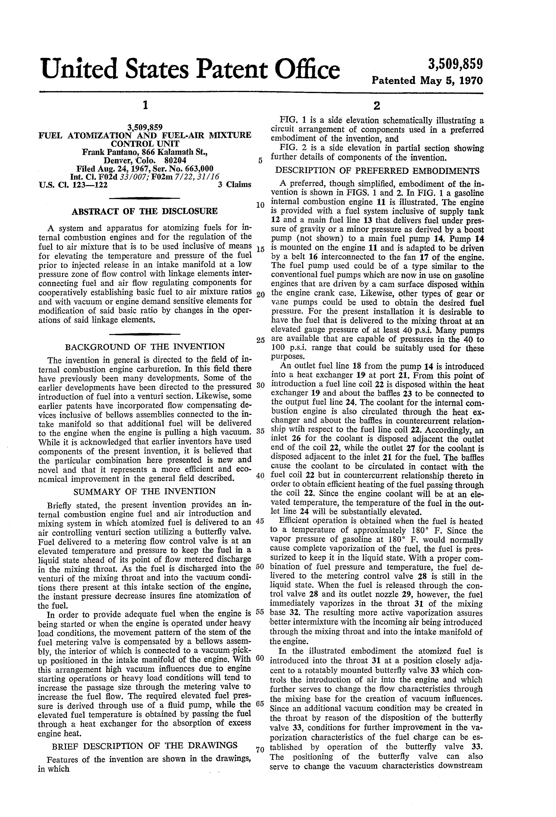
United States Patent Office 3,509,859 Patented May 5, 1970
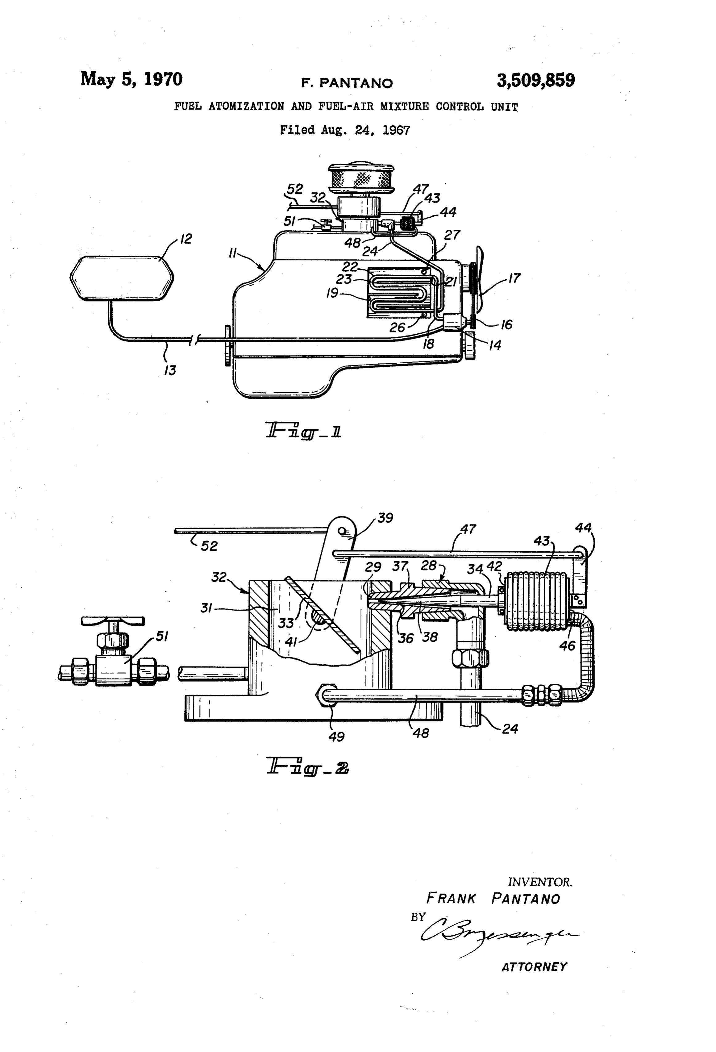
FIG. 1 is a side elevation schematically illustrating a
FUEL ATOMIZATION AND FUELAR MIXTURE
circuit arrangement of components used in a preferred
CONTROL UNIT embodiment of the invention, and
Frank Pantano, 866 Kalamath St. FIG. 2 is a side elevation in partial section showing Denver, Colo. 80204 further details of components of the invention.
Filed Aug. 24, 1967, Ser. No. 663,000 DESCRIPTION OF PREFERRED EMBODIMENTS
U.S. C. 123-122 3 Claims A preferred, though simplified, embodiment of the in yention is shown in FIGS. 1 and 2. In FIG. 1 a gasoline
O internal combustion engine 11 is illustrated. The engine
ABSTRACT OF THE DISCLOSURE is provided with a fuel system inclusive of Supply tank 12 and a main fuel line 13 that delivers fuel under pres
A system and apparatus for atomizing fuels for in Sure of gravity or a minor pressure as derived by a boost ternal combustion engines and for the regulation of the pump (not shown) to a main fuel pump 14. Pump 14 fuel to air mixture that is to be used inclusive of means 15 is mounted on the engine 11 and is adapted to be driven for elevating the temperature and pressure of the fuel by a belt 16 interconnected to the fan 17 of the engine. prior to injected release in an intake manifold at a low The fuel pump used could be of a type similar to the preSSure Zone of flow control with linkage elements inter conventional fuel pumps which are now in use on gasoline connecting fuel and air flow regulating components for engines that are driven by a cam surface disposed within cooperatively establishing basic fuel to air mixture ratios 20 the engine crank case. Likewise, other types of gear or and with vacuum or engine demand sensitive elements for Vane pumps could be used to obtain the desired fuel modification of said basic ratio by changes in the oper pressure. For the present installation it is desirable to ations of said linkage elements. have the fuel that is delivered to the mixing throat at an elevated gauge pressure of at least 40 p.s. i. Many pumps 25 are available that are capable of pressures in the 40 to
BACKGROUND OF THE INVENTION 100 p.s. i. range that could be suitably used for these purposes.
The invention in general is directed to the field of in ternal combustion engine carburetion. In this field there An outlet fuel line 18 from the pump 14 is introduced have previously been many developments. Some of the into a heat exchanger 19 at port 21. From this point of earlier developments have been directed to the pressured 30 introduction a fuel line coil 22 is disposed within the heat introduction of fuel into a venturi section. Likewise, some exchanger 19 and about the baffles 23 to be connected to earlier patents have incorporated flow compensating de the output fuel line 24. The coolant for the internal com vices inclusive of bellows assemblies connected to the in bustion engine is also circulated through the heat ex take manifold so that additional fuel will be delivered changer and about the baffles in countercurrent relation to the engine when the engine is pulling a high vacuum. 35 ship wtih respect to the fuel line coil 22. Accordingly, an While it is acknowledged that earlier inventors have used inlet 26 for the coolant is disposed adjacent the outlet end of the coil 22, while the outlet 27 for the coolant is components of the present invention, it is believed that disposed the particular combination here presented is new and adjacent to the inlet 21 for the fuel. The baffles novel and that it represents a more efficient and eco Gause the coolant to be circulated in contact with the nomical improvement in the general field described. 40 fuel coil 22 but in countercurrent relationship thereto in
SUMMARY OF THE INVENTION
order to obtain efficient heating of the fuel passing through the coil 22. Since the engine coolant will be at an ee
Briefly stated, the present invention provides an in Yated temperature, the temperature of the fuel in the out ternal combustion engine fuel and air introduction and let line 24 will be substantially elevated. mixing system in which atomized fuel is delivered to an Efficient operation is obtained when the fuel is heated air controlling venturi section utilizing a butterfly valve. to a temperature of approximately 180° F. Since the Fuel delivered to a metering flow control valve is at an Vapor pressure of gasoline at 180° F. would normally elevated temperature and pressure to keep the fuel in a cause complete vaporization of the fuel, the fuel is pres. liquid state ahead of its point of flow metered discharge Surized to keep it in the liquid state. With a proper com in the mixing throat. As the fuel is discharged into the bination of fuel pressure and temperature, the fuel de venturi of the mixing throat and into the vacuum condi livered to the metering control valve 28 is still in the tions there present at this intake section of the engine, liquid state. When the fuel is released through the con the instant pressure decrease insures fine atomization of trol valve 28 and its outlet nozzle 29, however, the fuel the fuel. immediately vaporizes in the throat 31 of the mixing In order to provide adequate fuel when the engine is base 32. The resulting more active vaporization assures being started or when the engine is operated under heavy better intermixture with the incoming air being introduced load conditions, the movement pattern of the stem of the through the mixing throat and into the intake manifold of fuel metering valve is compensated by a bellows assem the engine.
bly, the interior of which is connected to a vacuum pick In the illustrated embodiment the atomized fuel is up positioned in the intake manifold of the engine. With 60 introduced into the throat 31 at a position closely adja this arrangement high vacuum influences due to engine cent to a rotatably mounted butterfly valve 33 which con starting operations or heavy load conditions will tend to trols the introduction of air into the engine and which increase the passage size through the metering valve to further serves to change the flow characteristics through increase the fuel flow. The required elevated fuel pres the mixing base for the creation of vacuum influences.
sure is derived through use of a fluid pump, while the Since an additional vacuum condition may be created in elevated fuel temperature is obtained by passing the fuel the through a heat exchanger for the absorption of excess valvethroat 33, by reason of the disposition of the butterfly conditions for further improvement in the va engine heat. porization characteristics of the fuel charge can be es BRIEF DESCRIPTION OF THE DRAWINGS 70 tablished by operation of the butterfly valve 33. Features of the invention are shown in the drawings, The positioning of the butterfly valve can also in which serve to change the vacuum characteristics downstream
Page 3
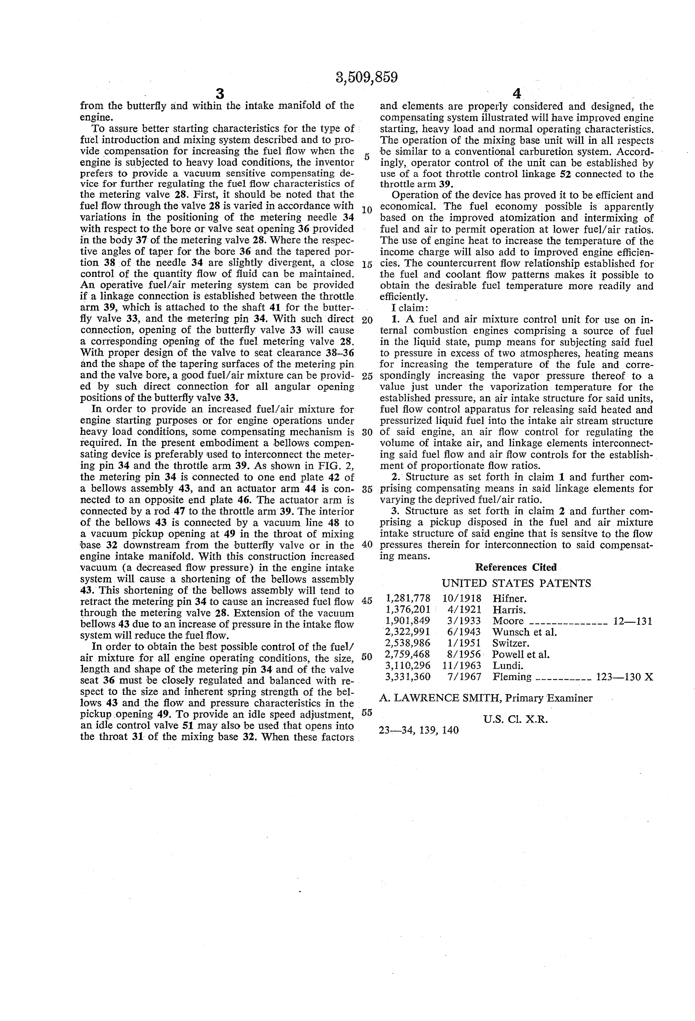
from the butterfly and within the intake manifold of the and elements are properly considered and designed, the engine. compensating system illustrated will have improved engine To assure better starting characteristics for the type of starting, heavy load and normal operating characteristics. fuel introduction and mixing system described and to pro The operation of the mixing base. unit will in all respects vide compensation for increasing the fuel flow when the be similar to a conventional carburetion system. Accord engine is subjected to heavy load conditions, the inventor ingly, operator control of the unit can be established by prefers to provide a vacuum sensitive compensating de use of a foot throttle control linkage 52 connected to the vice for further regulating the fuel flow characteristics of throttle arm. 39.
the metering valve 28. First, it should be noted that the Operation of the device has proved it to be efficient and fuel flow through the valve 28 is varied in accordance with O economical. The fuel economy possible is apparently variations in the positioning of the metering needle 34 based on the improved atomization and intermixing of with respect to the bore or valve seat opening 36 provided fuel and air to permit operation at lower fuel/air ratios, in the body 37 of the metering valve 28. Where the respec The use of engine heat to increase the temperature of the tive angles of taper for the bore 36 and the tapered por income charge will also add to improved engine efficien tion 38 of the needle 34 are slightly divergent, a close 5 cies. The countercurrent flow relationship established for control of the quantity flow of fluid can be maintained. the fuel and coolant flow patterns makes it possible to An operative fuel/air metering system can be provided obtain the desirable fuel temperature more readily and if a linkage connection is established between the throttle efficiently.
arm 39, which is attached to the shaft 41 for the butter I claim:
fly valve 33, and the metering pin 34. With such direct 20 1. A fuel and air mixture control unit for use on in connection, opening of the butterfly valve 33 will cause ternal combustion engines comprising a source of fuel a corresponding opening of the fuel metering valve 28. in the liquid state, pump means for subjecting said fuel With proper design of the valve to seat clearance 38-36 to pressure in excess of two atmospheres, heating means and the shape of the tapering surfaces of the metering pin for increasing the temperature of the fule and corre and the valve bore, a good fuel/air mixture can be provid 25 spondingly increasing the vapor pressure thereof. to a ed by such direct connection for all angular opening value just under the vaporization temperature for the positions of the butterfly valve 33. established pressure, an air intake structure for said units, In order to provide an increased fuel/air mixture for fuel flow control apparatus for releasing said heated and engine starting purposes or for engine operations under pressurized liquid fuel into the intake air stream structure heavy load conditions, some compensating mechanism is 30 of said engine, an air flow control for regulating the required. In the present embodiment a bellows compen volume of intake air, and linkage elements interconnect sating device is preferably used to interconnect the meter ing said fuel flow and air flow controls for the establish ing pin 34 and the throttle arm. 39. As shown in FIG. 2, ment of proportionate flow ratios. the metering pin 34 is connected to one end plate 42 of 2. Structure as set forth in claim 1 and further com a bellows assembly 43, and an actuator arm 44 is con 35 prising compensating means in said linkage elements for nected to an opposite end plate 46. The actuator arm is varying the deprived fuel/air ratio. connected by a rod. 47 to the throttle arm 39. The interior 3. Structure as set forth in claim 2 and further com of the bellows 43 is connected by a vacuum line 48 to prising a pickup disposed in the fuel and air mixture a vacuum pickup opening at 49 in the throat of mixing intake structure of said engine that is sensitve to the flow base 32 downstream from the butterfly valve or in the 40 pressures therein for interconnection to said compensat engine intake manifold. With this construction increased ing means.
vacuum (a decreased flow pressure) in the engine intake References Cited system will cause a shortening of the bellows assembly UNITED STATES PATENTS 43. This shortening of the bellows assembly will tend to retract the metering pin 34 to cause an increased fuel flow 45 1,281,778 10/1918 Hifner.
through the metering valve 28. Extension of the vacuum 1,376,201 4/1921 Harris.
bellows 43 due to an increase of pressure in the intake flow 1,901,849 3/1933 Moore -------------- 12-131. system will reduce the fuel flow. 2,322,991 6/1943 Wunsch et al.
In order to obtain the best possible control of the fuel/ 2,538,986 1/1951 Switzer.
air mixture for all engine operating conditions, the size, 50 2,759,468 8/1956. Powell et al.
length and shape of the metering pin 34 and of the valve 3,110,296 11/1963 Lundi.
seat 36 must be closely regulated and balanced with re 3,331,360 7/1967 Fleming --------- 123-130 X spect to the size and inherent spring strength of the bel A. LAWRENCE SMITH, Primary Examiner lows 43 and the flow and pressure characteristics in the pickup opening 49. To provide an idle speed adjustment, 55 U.S. C. X.R. an idle control valve 51 may also be used that opens into 23-34, 139, 140 the throat 31 of the mixing base 32. When these factors
Page 4
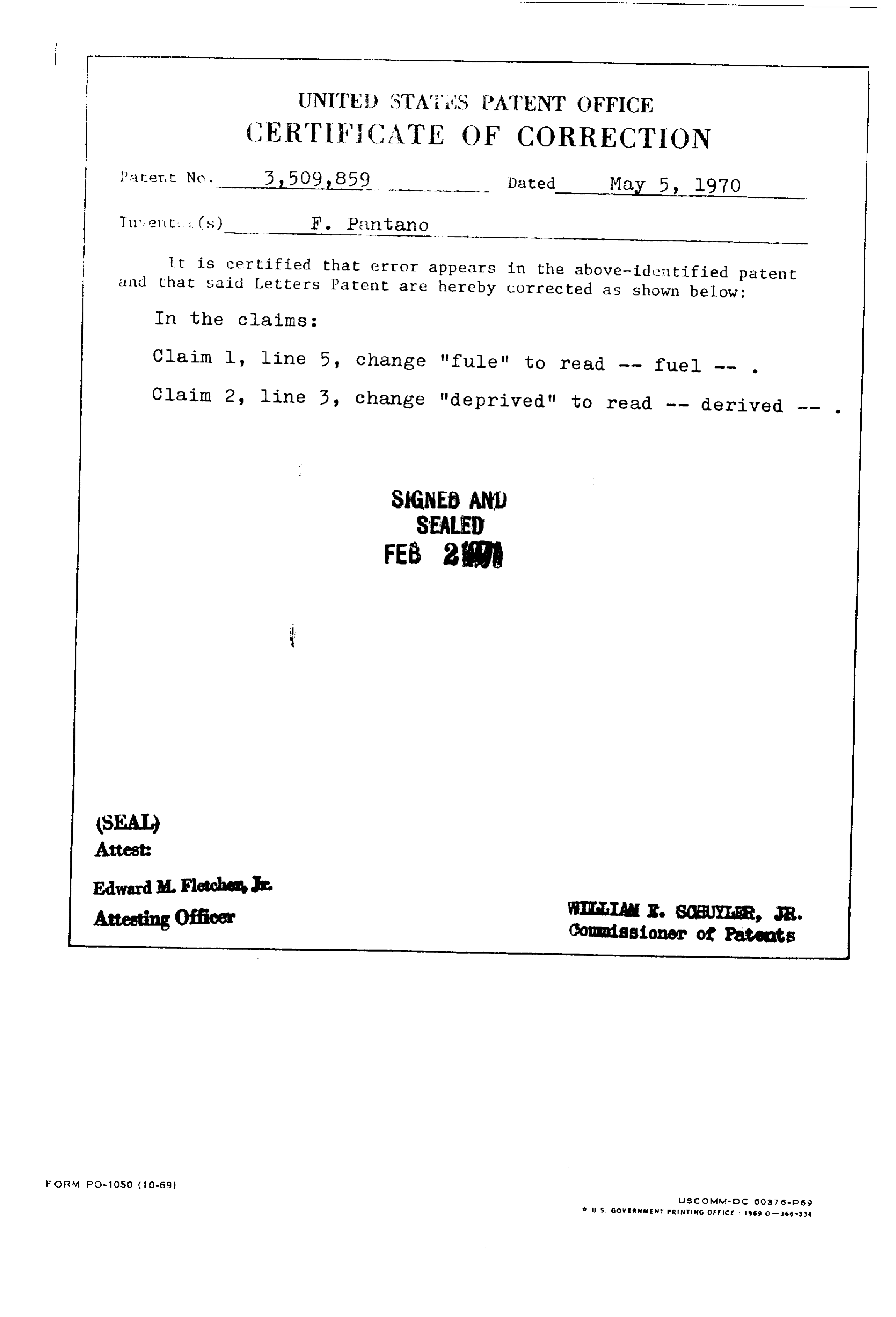
(CERT FCATE OF CORRECTION
a fert Noy. 3,509,859 - Dated May 5. l97O
it is certified that error appears in the above-identified patent and that said Letters Patent are hereby corrected as shown below: In the claims:
Claim l, line 5, change "fulle" to read -- fuel -- . Claim 2, line 3, change "deprived" to read -- derived -- .
SIGNED AND
SEAL ED
FEB 2.
Edward M. Fletches
Attesting Officer WIA. E. SCBUYER, Cordissioner JR.
of Patents
J.S. Go WERMEN PRENTING cFF ice : is O-36s-334
Provenance
- Collection
- Cited prior art
- Original PDF
- patentimages.storage.googleapis.com →
- Filed
- 1967-08-24
- Pages
- 4
- Method
- pdftotext (the PDF's own text layer) + pdftoppm 300dpi page scans
- Source
- Google Patents bibliographic record
- Granted
- 1970-05-05
- Inventors
- Frank Pantano
- Transcribed from
- patentimages.storage.googleapis.com →