patent · US6349718
Device for heating with solar energy
26 February 2002
Page 1 — bibliographic record
(12) United States Patent (10) Patent No.: US 6,349,718 B1 Ven et al. (45) Date of Patent: Feb. 26, 2002
(54) DEVICE FOR HEATING WITHSOLAR 4,159,710 A 7/1979 Prast .......................... 126/692 ENERGY 4,229.076 A * 10/1980 Chromie ..................... 359/853
(75) Inventors: Livien Domien Ven, Antwerp.; Michel 5,374,317 A 12/1994 Lamb et al. ................ 126/692 Sureda, Borgerhout, both of (BE) 5,899,199 A * 5/1999 Mills .......................... 126/692 (73) Assignee: Suria Holdings, societe a FOREIGN PATENT DOCUMENTS responsabilite limitee (LU) EP O O76 455 A2 * 4/1983
(*) Notice: Subject to any disclaimer, the term of this WO WO-96/30705 A1 * 10/1996 patent is extended or adjusted under 35
* cited by examiner
(22) PCT Filed: Feb. 9, 1999 Primary Examiner James C. Yeung (86) PCT No.: PCT/BE99/00017 ASSistant Examiner Josiah C. Cocks (74) Attorney, Agent, or Firm-Bacon & Thomas, PLLC
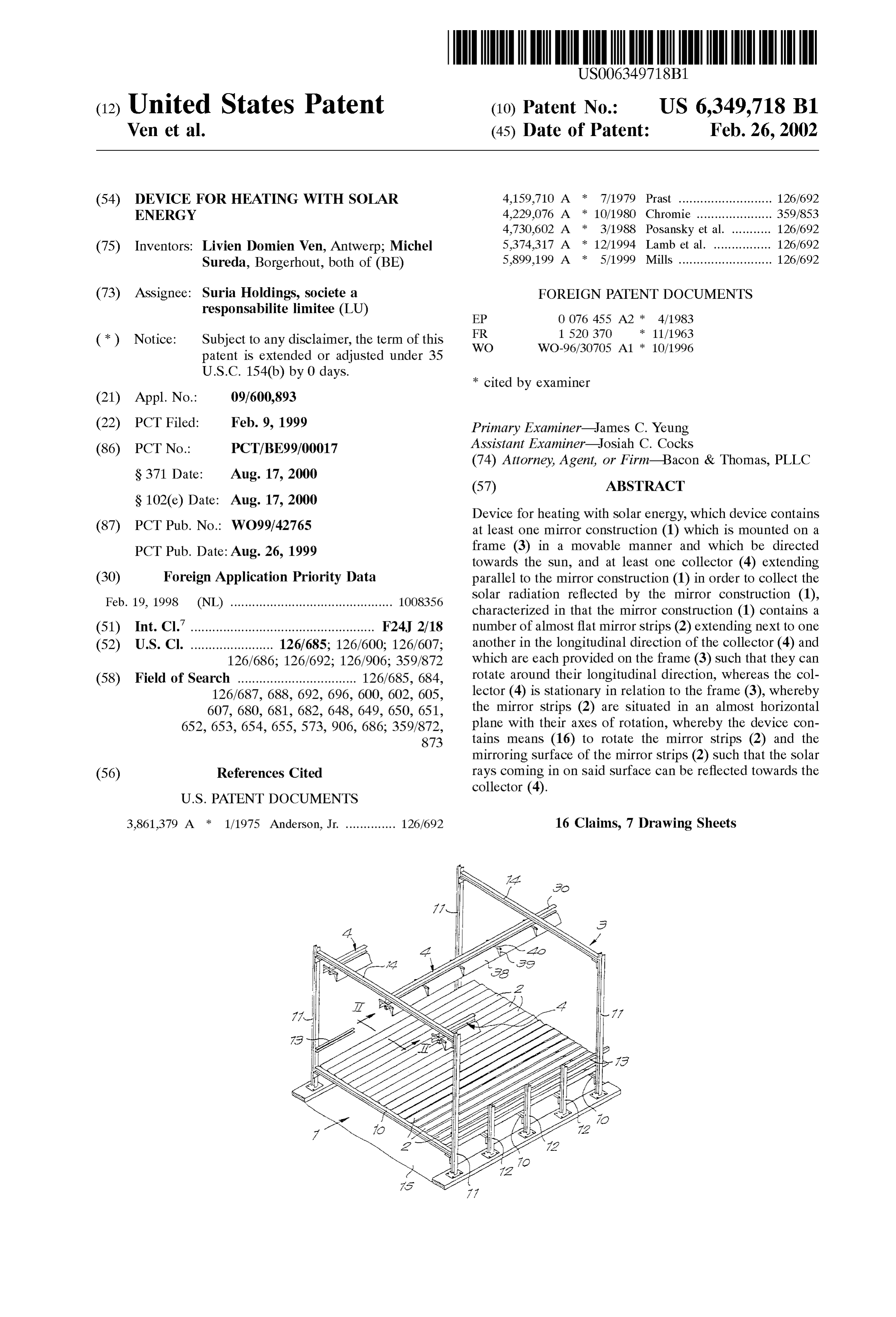
Device for heating with Solar energy, which device contains (87) PCT Pub. No.: WO99/42765 at least one mirror construction (1) which is mounted on a PCT Pub. Date: Aug. 26, 1999 frame (3) in a movable manner and which be directed towards the Sun, and at least one collector (4) extending (30) Foreign Application Priority Data parallel to the mirror construction (1) in order to collect the Feb. 19, 1998 (NL) ............................................. 10O8356 Solar radiation reflected by the mirror construction (1), characterized in that the mirror construction (1) contains a (51) Int. Cl." ................................................... F24J 2/18 number of almost flat mirror Strips (2) extending next to one (52) U.S. Cl. ....................... 126/685; 126/600; 126/607; another in the longitudinal direction of the collector (4) and 126/686; 126/692; 126/906; 359/872 which are each provided on the frame (3) Such that they can (58) Field of Search ................................. 126/685, 684, rotate around their longitudinal direction, whereas the col 126/687, 688, 692, 696, 600, 602, 605, lector (4) is stationary in relation to the frame (3), whereby 607, 680, 681, 682, 648, 649, 650, 651, the mirror Strips (2) are situated in an almost horizontal 652, 653, 654, 655, 573,906, 686; 35.9/872, plane with their axes of rotation, whereby the device con 873 tains means (16) to rotate the mirror Strips (2) and the mirroring Surface of the mirror Strips (2) Such that the Solar (56) References Cited rays coming in on Said Surface can be reflected towards the
collector (4).
3,861,379 A 1/1975 Anderson, Jr. .............. 126/692 16 Claims, 7 Drawing Sheets
Page 2
Drawing sheet — no readable text.
Page 3
Drawing sheet — no readable text.
Page 4
Drawing sheet — no readable text.
Page 5
Drawing sheet — no readable text.
Page 6
Drawing sheet — no readable text.
Page 7
Drawing sheet — no readable text.
Page 8
Drawing sheet — no readable text.
Page 9
DEVICE FOR HEATING WITH SOLAR towards the middle collector and that, after the Sun has ENERGY massed its highest point during the day, i.e. in the afternoon, the first series of mirror strips reflect towards the middle
The present invention concerns a device for heating with collector and the Second Series of mirror Strips reflect Solar energy, which device contains at least one mirror towards the collector situated to the west thereof. construction which is mounted on a frame and which can be In fact, the mirror construction can be regarded as two directed towards the Sun, and at least three collectors at Segmented, Semi-parabolic mirrors which extend parallel to equal distance from each other, extending parallel to the one another and whose Segments have been flattened have mirror construction in order to collect the Solar radiation been brought in a horizontal plane. reflected by the mirror construction, whereby the mirror The first mirror construction can be further extended with construction contains a number of almost flat mirror Strips one or Several additional Series of mirror Strips and with an extending next to one another in the longitudinal direction of extra collector for every Series.
the collectors and with their longitudinal direction The rotation device for rotating the mirror Strips can be northward/southward and which are each provided on the means to rotate at least a number of the mirror Strips, for frame Such that they can rotate around their longitudinal 15 example all the mirror Strips situated between two collectors direction, whereas the collectors are Stationary in relation to or all the mirror Strips together, Simultaneously and to the the frame, whereby the mirror Strips are situated in an almost Same eXtent.
horizontal plane with their axes of rotation, whereby the The device may include a wheel, for example a Sprocket device contains means to rotate the mirror Strips and the wheel or a toothed wheel on at least one end of each of the mirroring Surface of the mirror StripS Such that the Solar rays mirror Strips, an endless element, for example a chain or coming in on Said Surface can be reflected towards the toothed belt, working in conjunction with all these wheels, collectors and control means commanding the means to and drive means for driving this element.
rotate in function of the position of the Sun. The collector preferably contains at least one heat U.S. Pat. No. 3,861,379 discloses a device of the above absorbing pipe and at least one reflector, preferably consist mentioned type except that it contains only one collector All 25 ing of two parabolic bent mirrors, directed towards the pine mirror Strips are directed to this Single collector and are Situated in between and which is erected above the pipe like pivoted together for tracking the Sun. a cap for collecting the Solar rays reflected by the mirror When the Sun is low, the angle between the incident Solar construction and for reflecting them to the pipe. rays and the rays reflected towards the collector will he This pipe preferably is a double-walled glass tube whose larger than 90 for a number of the mirror strips, what inner wall is coated with a heat-absorbing material on the reduces the efficiency. outside and with a vacuum between both walls. Through this Devices of the kind described in the first paragraph are pipe may extend a metal tube, whereas the Space between disclosed amongst others in FR-A-1,520,370 and U.S. Pat. this metal tube and the pipe may be filled with a heat No. 4,229,229 transferring material Such as Steel wool. These known devices contain two or more collectors and 35 In order to better explain the characteristics of the underneath each collector a Series of mirror Strips which invention, the following two preferred embodiments of a may be rotated in function of the position of the Sun. device for heating with Solar energy according to the inven The mirror Strips of each Series of mirror Strips are tion are described as an example only without being limi always directed with their mirroring Surface towards a same tative in any way, with reference to the accompanying single collector which is then situated in the middle above 40 drawings, in which:
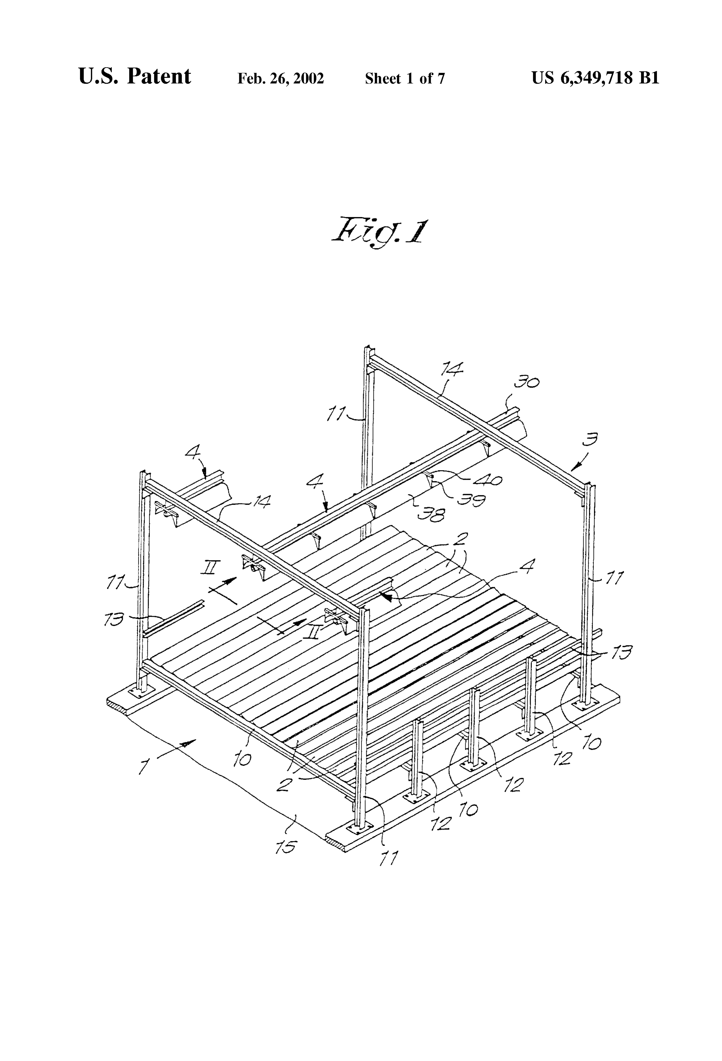
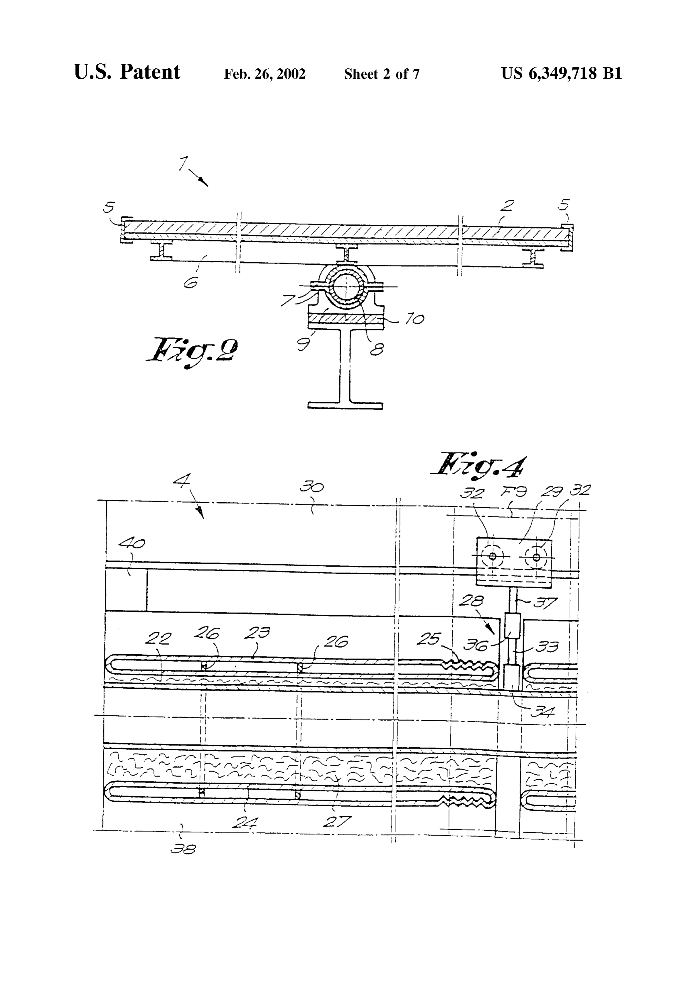
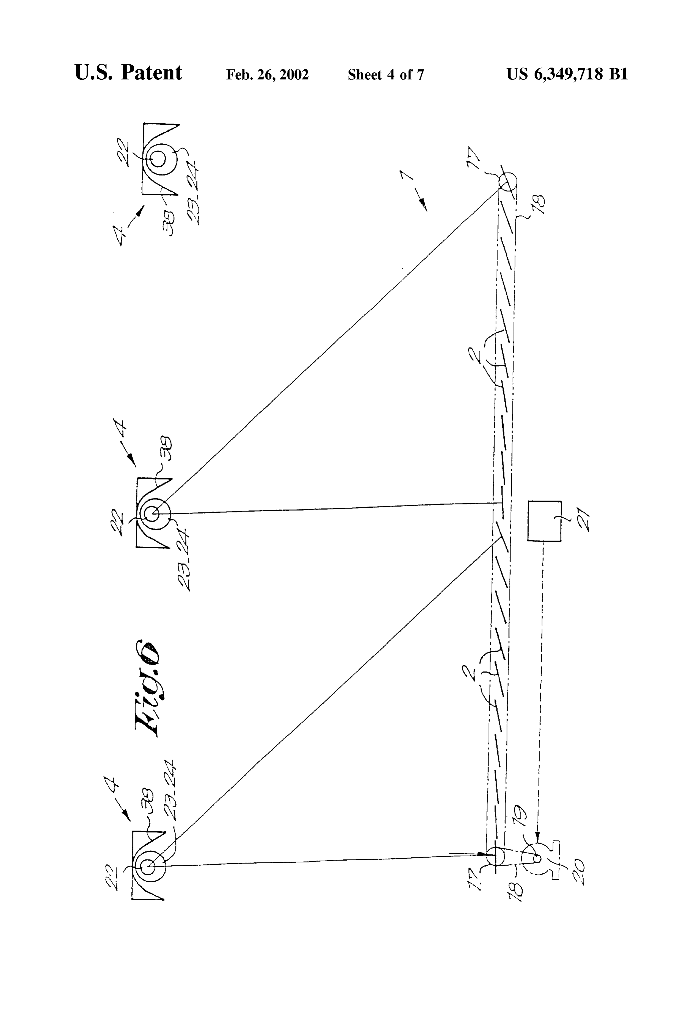
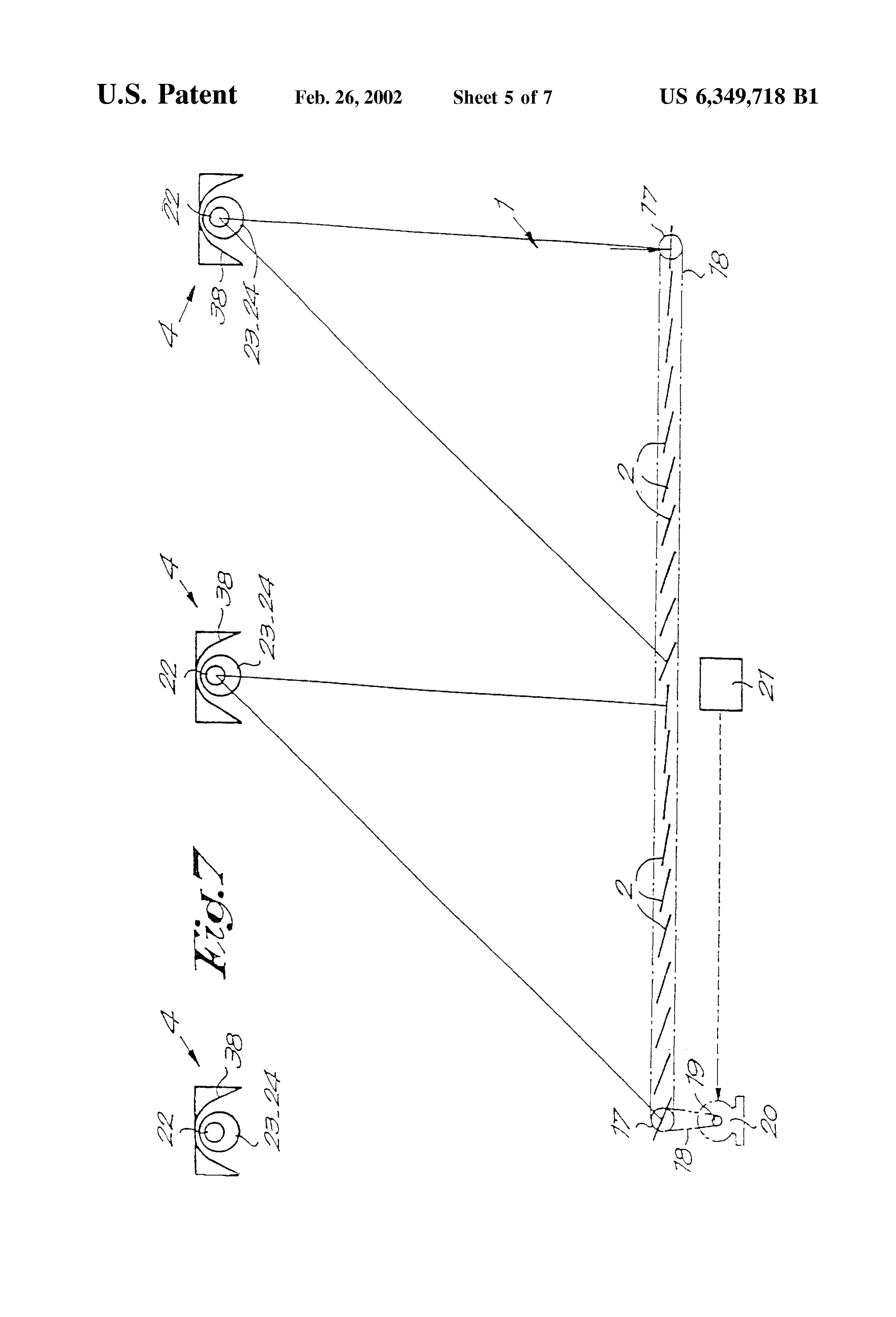
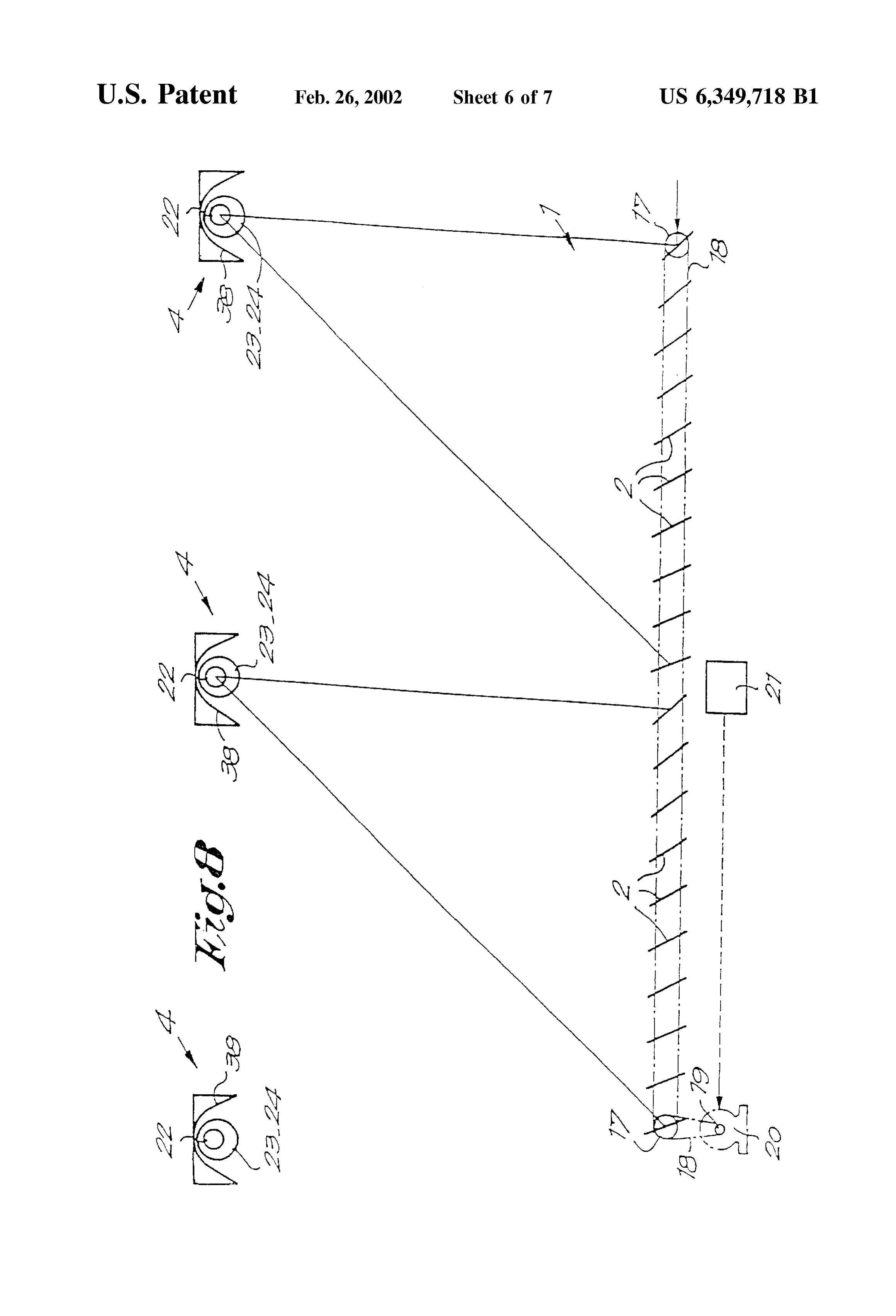
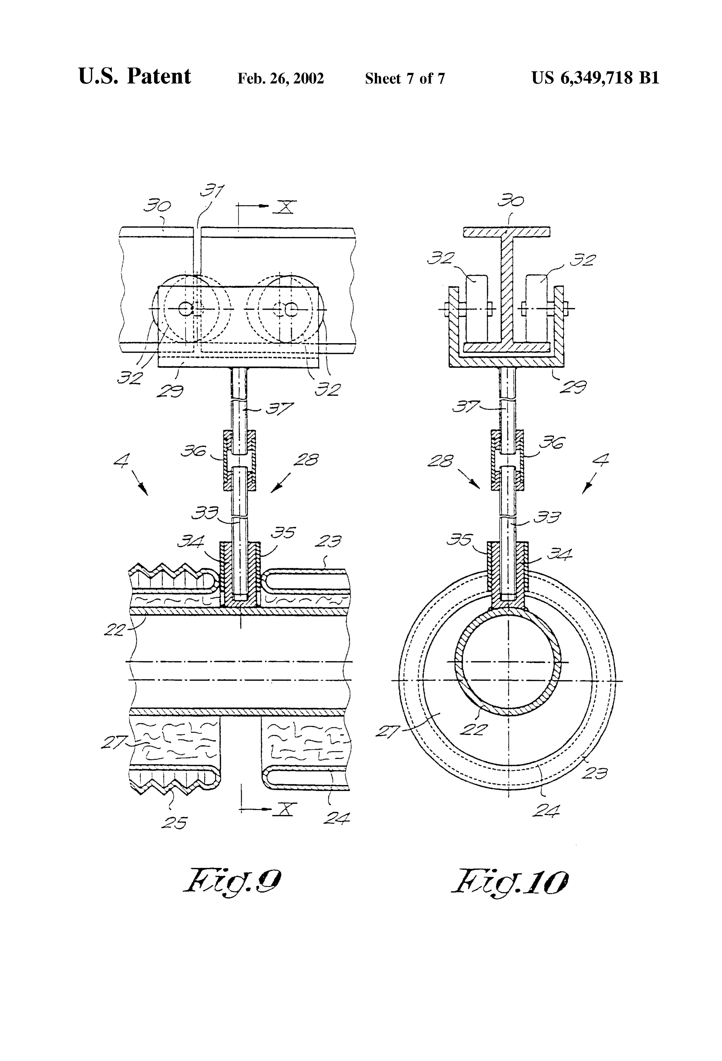
the Series of mirror Strips. FIG. 1 shows a very schematic view in perspective of the In fact the last mentioned devices may be considered as device according to the invention;
consisting of two or more of the above mentioned known FIG. 2 shows a section according to line II-II in FIG. 1 device as described in U.S. Pat. No. 3,861,379, places one to a larger Scale;
after the other. 45 FIG. 3 shows a view in perspective with the collector of The angle between the incident Solar rays and the rays the device according to FIGS. 1 and 2 being partially cut out; reflected towards the collector will be larger than 90 for a FIG. 4 schematically shows a longitudinal section of the number of the mirror Strips, except when the Sun is in its collector from FIG. 3;
highest position above the mirror construction. The moment FIG. 5 schematically shows a front view of the device at which this angle becomes an acute angle coincides with 50 according to the invention;
different positions of the Sun for these mirror strips and thus FIGS. 6, 7 and 8 represent schematic front views analo takes place at different points in time. gous to those in FIG. 5, but with reference to two other Mirror Strips whose above-mentioned angle is larger than Situations of the device;
90 make the efficiency of the device decrease. FIG. 9 shows the detail which is indicated by FIG. 9 in The aim of the invention is to avoid this drawback. 55 FIG. 4 to a larger Scale,
To this aim, according to the invention, when three FIG. 10 shows a section according to line X-X in FIG. adjacent collectors are considered, the mirror Strips there 9.
under are divided into two Series, the mirror Strips of one As represented in FIG. 1 the device for heating with solar Series reflecting to the collector Situated in the middle while energy according to the invention mainly consists of a mirror the mirror strips of the other series reflect to the one of the 60 construction 1 which is formed of a number of flat mirror other two collectors situated above the Series, the control Strips 2 situated next to one another which are mounted on means commanding the means to rotate in Such way that, in a frame 3 in a rotating manner according to their longitudinal the morning, a first Series of mirror Strips situated between direction or parallel to their longitudinal axis, and a collector the middle collector and the collector situated to the east 4 erected on top of it which is fixed stationary on the thereof reflect towards this latter collector, whereas the 65 above-mentioned frame 3
Second Series of mirror Strips situated between the middle The mirror Strips 2 are flat and parallel to one another collector and the collector situated to the west thereof reflect with their longitudinal direction.
Page 10
They are for example made of glass with a mirroring coat 6 inches (about 15 cm) long which is surrounded by double on the top side and preferably a coat which can resist walled glass tubes 23–24. AS opposed to Steel tubes, glass Sandstorms on the bottom Side, Such as a coat on the basis tubes are not permeable to hydrogen, they are leSS expensive of rubber or plastic. and they can have a Smaller diameter. They have a width of for example almost 50 cm, a length The outer tube-shamed wall 23 of the tubes 23–24 is of about 3 m and a thickness of 3 mm. translucent, but the inner tube-shaped wall 24 is coated with Every mirror Strip 2 can rotate. AS is represented in detail a black, heat-absorbing layer on the outside which has for in FIG. 2, every mirror strip 2 is hooked on a frame 6 made example been Sputtered onto it.
of aluminium profiles by means or clamps 5, which frame is On the ends, the walls 23 and 24 are closed, and there is in turn fixed on a tube 8 by means of clamping brackets 7, a vacuum between these walls 23 and 24 which are for which tube is mounted in a bearing 9 every three metres example Situated at a distance of about 1 mm from one which is fixed on a horizontal cross-latch 10 which is part of another.
the frame 3.
All these cross-latches 10 are fixed with their ends to the This double-walled tube 23–24 is made of heat-resistant rest of the frame 3, namely to Standing profiles 11 or 12, at 15 glass, for example glass which is known under the brand a height of about 1.5 m above the ground, but adjustable in name Pyrex. The inner, black wall 24 can be heated up to height. temperatures of 300 to 500° C. The outer wall 23, however, Between two profiles 12 in a longitudinal Side are erected remains relatively cold.
three shorter profiles 11, for 1 example one shorter profile 11 The tube 23–24 is to 4 metres long, and in order to make every three metres. The profiles 11 extend up to a distance it possible for the inner wall 24 to expand, expansion above the mirror construction 1 and their top ends are bellows 25 are provided at one end of the outer wall 23, connected to one another and to the profiles 12 by means of preferably made of tempered class which has been fused to longitudinal profiles 13 in the longitudinal sides. the rest of the class wall 23.
The Standing profiles 12 are considerably higher than the In order to prevent the inner wall 2 from buckling when profiles 11 and their top ends are connected to one another it exerts Some force on the expansion bellows 25 as a result by means of horizontal cross-sectional profiles 14. The 25 of the expansion, glass rings 26 are clasped around Said Standing profiles 11 and 12 are fixed to a concrete foundation inner wall 24, for example by providing them over the wall 15. 24 when they are hot and by making them shrink by cooling Over the two longitudinal profiles 13 may possibly ride them, which make contact with the outer wall 3 only locally a trolley which is not represented in the figures for So as to limit the heat transfer.
maintaining, Washing or repairing the mirror construction 1. The space between the inner wall 24 and the steel pipe A rotation device 16 is provided to rotate the mirror strips 22, which has an atmospheric pressure, is filled with a 2 as a function of the position of the Sun, during the day as medium 27 which transfers heat, for example steel wool the mirror Strips are directed, with their longitudinal direc Surrounded by a thin aluminium sheet having a thickness of tion northward/southward. for example 0.3 mm, which is closely connected to the tube The rotation device 16, which is only represented in 35 22 and the wall 24.
FIGS. 5 to 8 for clarity's sake, includes a sprocket wheel 17 Moreover, the double-walled tube 23–24 rests on the on one end of every tube 8 which is connected to a Sprocket Steel tube 22 through the agency of Said medium 27. wheel19 via a chain 18 which is driven by a drive consisting The tube 22 extends over the entire length of the mirror of a stepping motor 20. Strips 2, but it can also extent over Several Series of mirror The device 16 further includes an electronic control 40 StripS 2 or mirror constructions 1 and even have a length of device 21 which controls this Stepping motor 20 as a 1 kilometre.
function of the position of the Sun, Such that the mirror Strips The double-walled tube 23–24, however, only has a 2 can follow the Sun. length of about 3 m, and several tubes 23–24 are provided In principle, the length of the device in the longitudinal one after the other around the steel tube 22 in the collector direction of the mirror Strips 2 is unlimited, and this length 45 4.
may amount to one kilometre. On he ends of the device and between two Successive It is clear that the mirror strips 2 erected in the north/ double-walled class tubes 23-24, the steel tube 22 is Sus South direction must have different mutual inclinations for pended to a trolley 29 by means of a suspension 28 rolling each position or the Sun in their croSS direction in order to over a I-profile 30 of the frame 3, as is schematically reflect the collected Solar rays to the only collector 4 which 50 represented in FIG. 4, and into more detail in FIGS. 9 and is hung in the middle above the mirror construction 1 on 10.
croSS-Sectional profiles 14. This I-profile 30, which extends over the entire length of According to the shown embodiment, the chain 18 the collector 4, but which is provided with an expansion extends around all the sprocket wheels 17 and the device 16 joint 31 at regular distances, is Suspended to horizontal only includes a single Stepping motor 20 which drives all the 55 croSS-Sectional profiles 14.
sprocket wheels 17 via a sprocket wheel19 and the chain 18, The trolley 29 is a U-profile whose two legs carry two and thus rotates all the mirror Strips 2 simultaneously and to Small wheels 32 on their sides turned to one another. AS is the same extent. represented in FIG. 10, the front and rear wheels 32 are not Each collector 4 is situated at a height above the mirror placed on one and the same axis, but they are shifted in construction 1 which is for example half of the width of the 60 relation to one another in the driving direction, Such that mirror construction, for example at a height of twelve only one wheel32 at a time rides over an expansion joint 31 metres. However, the height can also be leSS and amount to while the trolley 29 is still resting with three wheels 32 on for example Six metres. the I-profile 30. Thus, the trolley 29 is prevented from These collectors 4 extends in the longitudinal direction of Swinging as it rides over an expansion joint 31. the mirror Strips 2. 65 As is represented in detail in FIGS. 9 and 10, the As is represented in detail in FIGS. 3 and 6 this collector suspension 28 may consist of a first bar 33 which is screwed 4 contains a metal, preferably a Steel tube 22 of for example in a bush 34 which is welded on the steel tube 22 and which
Page 11
S 6 is surrounded by insulating material 35 between the ends of The three above-described collectors 4 are suspended to two neighbouring tubes 23–24 on the one hand, and which a I-profile 30, in that the mirror strips 2 have a different is Screwed in a sleeve 36 on the other hand, and of a Second inclination in their croSS direction and in that they are all bar 37 which is welded onto the trolley 29 and which is also driven by one.
Screwed in the above-mentioned sleeve 36, Such that, as the One of the three collectors 4 is erected in the middle, as sleeve 36 turns, the bars 33 and 37 are drawn towards one in the above-mentioned embodiment, whereas the other two another or are moved away from one another. The Screw are situated above the longitudinal edges, to the east and to thread is directed in one and the Same direction on both ends the west respectively of this middle collector 4. of the bar 33, but the Screw threads on both ends screwed in The mirror Strips 2 are inclined Such that they coincide the sleeve 36 are directed in the opposite Sense. 1O with two longitudinal Semi-parabolas which have been
The collector 4 further contains a number of reflectors 38 divided into Segments and whereby the Segments have been which each consist of two longitudinal mirrors which are flattened and lowered in one and the same horizontal plane, and whereby the two Semi-parabolas are practically parallel fixed to one another in the length above the glass tube 23-24 to one another.
and which form a cap over the heat-absorbing pipe formed The mirror strips 2 which coincide with the one semi by the wall 24. The cross section of each mirror is a part, for 15 parabola reflect towards one collector 4, whereas those example half, of a parabola. coinciding with the other Semi-parabola reflect towards The reflectors 38 are suspended on a cross-sectional another collector 4, whereby, when the Sun has reached its profile 40 by means of bars 39 which is fixed to the bottom highest point, all the mirror Strips 2 are rotated together over side of the I-profile 30. an angle, So that they each reflect towards another collector Each reflector 38 is directed with its mirroring side on 4. This angle is 22.5 when the width of the mirror con this wall 24 which is practically situated on the focal line of Struction 1 is equal to twice the height at which the collectors the two parabolic halves of this reflector 38. 4 are situated, and the distance between the collectors 4 is The reflector 3, has a length which is almost equal to the thus equal to this height.
length of a double-walled glass tube 23–24, and the collector In FIG. 5 the mirror strips 2 are represented at the time 4 has several of those reflectors 38 which are situated in line 25 the Sun Stands on the horizon in the east. The first Series or above the mirror construction 1. half of the mirror strips 2 situated on the side of the Sun The opening at the bottom of the reflector 38 is calculated reflect the collected Solar rays towards the collector 4 such that the Solar rays which are reflected by all the mirror situated eastward. The other series or half of the mirror strips strips 2 of the mirror construction 1 fall in it and are thus 2 reflect towards the middle collector 4. reflected towards the inner wall 24 of the glass tube 23-24, It is clear that in the farthest position represented in FIG. insofar as they did not fall directly on this wall 24. 5, the reflection is rather theoretical, Since the mirror Strips If the height of the collector 4 above the mirror con are situated in each other's Shadow when the position of the Struction 1 is about half of the width of the latter this opening Sun is this low.
is Such that it can collect an angle of rays of 90, and it is The mirror strips 2 are all continuously rotated by the for example about 72 cm. When the collector 4 is positioned 35 means 16, but they keen reflecting towards the above lower, the angle can be larger, for example up to 135. mentioned collectors 4 as the Sun rises until they take the For practical reasons, the length of the mirror Strips 2 is position in which they are represented in FIG. 6, when the limited to for example 3 m, but Several mirror constructions Sun is at its highest point. Before noon, they are rotated over 1 can be put one after the other in the longitudinal direction, 45 in total.
whereby the tubes 8 of a number of mirror strips 2 or even 40 At noon, i.e. when the Sun has reached its highest point, all the mirror Strips 2 situated in line can form an uninter all mirror Strips 2 are rotated, in the given example over rupted whole, So that a single Stepping motor 20 can 22.5, into the position represented in FIG. 7.
Simultaneously rotate a number of these mirror Strips 2 The mirror strips 2 of the first series now reflect towards which are coupled to one another, or all of them at once. the middle collector 4 and the other mirror strips 2 towards Also the frame 3 and among others the longitudinal 45 the collector 4 situated westward.
profiles 13 and the I-profile 30, abstracting from the expan In the course of the afternoon, all the mirror Strips 2 are Sion joints 31, may continue uninterruptedly over Several further simultaneously rotated by the means 16 over a total Series of mirror constructions 1. angle of 45 until the Sun goes down in the west. The mirror This also goes for the collector 4 Suspended on the Strips 2 are then situated in the position represented in FIG. I-profile 30 which may have a length of up to one kilometre. 50 8 and thus form the mirrored image of the situation before Moreover, several individual mirror constructions or the rotation.
mirror constructions situated one after the other in the At any time, the angle between the incident Solar rays longitudinal direction may also be situated next to one and the Solar rays reflected to a collector 4, which is another in the croSS direction. represented for some mirror strips 2 in FIGS. 5 to 8, is By making use of flat mirror Strips 2 instead of one or 55 smaller than 90°, so that the efficiency of the device is more parabolic mirrors, the construction is relatively simple. excellent.
Its maintenance is relatively easy, especially thanks to a AS all the mirror Strips 2 are always rotated together and trolley riding over the longitudinal profiles 13. to the same extent, the rotation device 16 has a simple In case of for example a Sandstorm, the mirror Strips can construction and the tracking of the Sun is rather easy. be rotated against the direction of the wind with their 60 It is clear that on both sides of the above-described mirror protected back Side. construction 1, additional mirror Strips 2 can be provided as The device has a large efficiency. Only for a very short is represented by means of a dashed line in FIGS. 5 to 8, in period in the early morning or late in the evening, the Strip. particular one or Several Series of mirror Strips 2 which During the rest of the day, little Solar energy is lost due to coincide with a Segmented Semi-parabola, but for every Shadows. 65 Series also one additional collector 4. The mirror strips 2 are directed with their longitudinal The additional Series of mirror Strips 2 situated eastward direction in the north/south direction. will reflect towards the collector 4 of the above-described
Page 12
mirror construction 1 Situated the most eastward in the 3. The device according to claim 1 wherein the mirror afternoon. In an analogous manner, an additional Series construction further includes at least one additional Series of situated westward will reflect towards the collector 4 of the mirror Strips corresponding to an additional collector. above-described mirror construction 1 Situated the most 4. The device according to claim 1 wherein the rotation westward before noon. device rotates at least a portion of Said mirror Strips Simul AS the mirror construction is divided in mirror Strips 2, taneously.
it is possible to put one or Several mirror Strips 2 entirely or 5. The device according to claim 1 wherein the rotation partly off-duty, for example by tilting them Separately So that device groups rotates all of Said mirror Strips of one of Said two
Simultaneously.
they are no longer directed towards the Sun, So as to thus 6. The device according to claim 4 wherein the rotation adjust the total amount of Solar energy which is collected by device includes wheels connected to each of Said mirror the device.
The present invention is by no means restricted to the wheels, and a driveelement
Strips, an endless device adapted to cooperate with Said arranged to drive Said element.
embodiments described above and represented in the accom 7. The device according to claim 1 wherein each collector panying drawings, on the contrary, Such a device for heating comprises at least one heat-absorbing tube and at least one with Solar energy can be made in all Sorts of variants while 15 reflector directed towards and positioned above Said tube, Still remaining within the Scope of the invention. Said at least one reflector arranged to direct light a concen What is claimed is: tration of light reflected from Said mirror Strips onto Said 1. A Solar power heating device comprising: tube.
a frame; 8. The device according to claim 7 wherein the reflector at least one mirror construction including a plurality of comprises two parabolic bent mirrors. 9. The device according to claim 7 wherein the tube elongated, rectangular, flat mirror Strips arranged in comprises parallel rows, each of Said mirror Strips having a shaped walla double-walled glass tube having an inner tube longitudinal centerline and an axis of rotation coexten exterior, Said coated with a heat-absorbing material on the outer tube-shaped wall being translucent, and
Sive with Said centerline and each of Said mirror Strips 25 further including a vacuum between said walls. being individually rotatable about Said axis of rotation, 10. The device according to claim 9 comprising a metal the axes of rotation of the mirror Strips arranged tube extending through Said double-walled glass tube, Substantially in a common plane; wherein a Space between this metal tube and the glass tube at least three equally spaced light receiving collectors is filled with a heat-transferring medium. Supported in an elevated relationship relative to and 11. The device according to claim 9 comprising a double parallel with the mirror Strips, with one of Said collec walled glass tube having an inner wall and an outer wall, tors comprising a central collector and two of Said Said inner wall having expansion bellows provided therein. collectors comprising end collectors, 12. The device according to claim 11 further comprising a rotation device adapted to pivotally rotate each of Said ringstube, disposed between the inner and outer walls of the glass
Said rings contacting Said outer wall locally.
mirror Strips about its respective axis of rotation; 35 13. The device according to claim 10 further comprising a control device arranged to control Said rotation device a plurality of glass tubes located above the mirror construc So as to maintain light reflected from Said plurality of tion and provided one after the other around a single metal mirror Strips incident on at least two of Said collectors, tube, Said glass tubes being Supported by Said metal tube. Said plurality of mirror Strips being divided into at least 14. The device according to claim 1 wherein Said collec two mirror Strip groups wherein each mirror Strip group 40 tors include a metal tube for heating a fluid, Said collectors is bounded by said central collector and by one of said further being Suspended at equal distances along a longitu end collectors, Said control device alternatively orient dinal profile of said frame by a trolley adapted to be ing Said mirror groups between at least two positions positioned at different points along Said longitudinal profile. wherein in a first position one of Said mirror groups 15. The device according to claim 14 wherein the longi reflects light to Said central collector and another of 45 tudinal profile includes expansion points, said trolley having Said mirror groups reflects light to one of Said end two front and two back wheels positioned along different collectors, and in a Second position, Said another of Said axes and shifted in relation to one another in the driving mirror groups reflects light to Said central collector and direction.
Said one of Said mirror groups reflects light to another 16. The device according to claim 14 wherein the metal of Said end collectors. 50 tube is Suspended by a Suspension device including two bars 2. The device according to claim 1 wherein the mirror joined together in a sleeve So as to be adjustable in relation construction comprises two Segmented, Semi-parabolic mir to one another by turning Said sleeve.
rors extending parallel to one another and having flattened
Segments arranged in a horizontal plane.
Provenance
- Collection
- Cited prior art
- Original PDF
- patentimages.storage.googleapis.com →
- Filed
- 1999-02-09
- Pages
- 12
- Method
- pdftotext (the PDF's own text layer) + pdftoppm 300dpi page scans
- Source
- Google Patents bibliographic record
- Granted
- 2002-02-26
- Inventors
- Livien Domien Ven; Michel Sureda; Suria Holdings Sarl
- Transcribed from
- patentimages.storage.googleapis.com →