patent · US5242565
Device for electrochemical generation of gases for the transportation of fluids and similar mediums
7 September 1993
Page 1 — bibliographic record
United States Patent (19) 11 Patent Number: 5,242,565 Winsel 45) Date of Patent: Sep. 7, 1993 (54) DEVICE FOR ELECTROCHEMICAL 4,402,817 9/1983 Maget ................ 204/301 GENERATION OF GASES FOR THE 4,489, 14 12/1984 Stafford et al. ... 429/61 TRANSPORTATION OF FILUIDS AND 4,556,612 12/1985 Thibault et al. ...................... 429/54 4,800,139 1/1989 Kenjyo .................................. 429/42
SMLAR MEDUMS 5,043,234 8/1991 Tomantschger et al. .......... 429/229 76 Inventor: August Winsel, D-Fasanenstr. 8a,
D-6233 Kelkheim, Fed. Rep. of Primary Examiner-John Niebling
Assistant Examiner-Kathryn Gorgos
Germany Attorney, Agent, or Firm-Rosen, Dainow and Jacobs (21) Appl. No.: 727,877 57 ABSTRACT 22 Filed: Jul. 10, 1991 The device according to the present invention com Related U.S. Application Data prises a galvanic cell including a gas generating elec trode, a counter electrode and an aqueous electrolyte 63 Continuation-in-part of Ser. No. 372,346, Jul. 10, 1989, enclosed in a housing. The device has one or more abandoned. openings, by which the generated gas is released to the Sll Int. C.’................................................ C25B 9/00 environment. The device also contains means for elec 52 U.S. C. .................................... 204/265; 204/266; trically connecting said gas generating electrode and 204/291; 204/283 said counter electrode and for establishing a current (58) Field of Search ............... 204/252,283, 284, 253, flow between said gas generating electrode and said 204/266, 258, 290 R, 292, 291, 264, 400; counter electrode for generating a predetermined quan 429/44, 42,27, 229, 54, 50,90, 61, 66, 150, 224, tity of gas by said gas generating electrode for release 206, 186, 18, 190, 209 from said opening of said galvanic cell. The objective of the cell is to generate and release oxygen or hydrogen (56) References Cited gas, thereby defining a new type of cell. The device is
3,622,397 1/1971 Belove .................................. 429/55 4,189,526 2/1980 Cretzmeyer et al. ................. 429/13 28 Claims, 6 Drawing Sheets
lavaravavaravav avava vava vava wa Cava have a vahala raw v. Va a vava was vava via at allX asa Cava
Cup
NNN (SSK3rk KK3R3 SA a ) r ZZZZZZZ N
Page 2
Drawing sheet — no readable text.
Page 3
Drawing sheet — no readable text.
Page 4
Drawing sheet — no readable text.
Page 5
Drawing sheet — no readable text.
Page 6
Drawing sheet — no readable text.
Page 7
Drawing sheet — no readable text.
Page 8
DEVICE FOR ELECTROCHEMICAL
tion and corrosion of the zinc take place close to the area where the platinum contacts the zinc.
GENERATION OF GASES FOR THE On the basis of the platinum wire/zinc experiment, a TRANSPORTATION OF FLUIDS AND SIMILAR device for the generation of hydrogen was designed ME OUMS some years ago, which consists of a coin-like zinc plate This application is a continuation-in-part of U.S. pa denumwith a center opening. Into this opening a bar of molyb tent application Ser. No. 07/372,346 filed Jul. 10, 1990 ing. In isorder secured by any suitable means such as solder to generate hydrogen gas, this corrosion now abandoned. element (zinc?molybdenum) is submerged into a aque The present invention relates to a device for the elec 10 ous solution of KOH.
trochemical generation of gases for the transportation It is noted that in German patent 2 139771 and Cana of fluids, lubricants and similar media. dian patent 961,420, an automatic press for lubricants is DESCRIPTION OF THE PRIOR ART described, which makes use of the above-mentioned It is known to use catalytic or electrochemical pro 15 metallic generated corrosion element. The hydrogen, which is by the corrosion element, drives a piston in a cesses in order to generate gases as means for the trans cylinder and forces the lubricant to penetrate from portation of fluids in technical applications. By catalytic inside of the cylinder decomposition of hydrazine into a mixture mainly con tion object. The rateviaofathis screw adapter to the lubrica process depends on the sisting of hydrogen and nitrogen, a pressurized gas is properties of the corrosion element and on the tempera generated, which is used to empty the water-filled tanks ture. Once the process has been started, no possibility of submarines within a short time. The gas mixture exists to change the rate.
contains ammonia in a concentration which is a function of the nature of the catalyst. The higher the concentra For many years zinc?/air cells utilizing alkaline as well tion of ammonia, the higher is the temperature of the as acidic electrolytes have been on the market in differ generated gas. This effect is used to operate the steering 25 ent sizes. These cells consume oxygen gas to effect nozzles of satellites. .. depolarization by extracting it from the air. These cells It is possible to use oxygen for similar purposes. The have not been used generally to produce a gas hitherto. oxygen gas is generated by the catalytic decomposition "An air depolarized cell", for example a "zincair of hydrogen peroxide using, for example, a silver cata cell', in operation is not able to produce a gas since its lyst. In both the hydrazine and hydrogen peroxide pro 30 reaction is dependent on the presence of oxygen gas as cesses noted above, a high quantity of heat is liberated part of the atmosphere in the cathode. by the catalytic reaction, which in general requires a In various types of primary batteries, the develop special heat management. The rate of the reaction is ment of gas has to be inhibited even in the discharged controlled by the influx of the liquid to the catalyst bed. state or under abusive conditions in order to prevent Accordingly, in such a process, the reaction can only be 35 damage of the apparatus driven by the cell. As noted, regulated or stopped by regulating or interrupting the gas development in a primary cell caused by zinc corro liquid flow. It has been proposed to use self-controlling sion or under abusive conditions leads to the develop catalytic reactors working similar to those used in the ment of high inside pressures and to the destruction of techniques of gas diffusion electrodes. Valve electrodes the cell and the apparatus. Therefore, it is an important are disclosed in U.S. Pat. No. 3,201,282 and German goal of the research on primary cells to avoid the gas patent 1,542,565. In these systems, the pressure of the evolution by corrosion for example of the zinc or of iron generated gas is the control parameter; that is, by using containing construction elements. a diluted aqueous solution of hydrazine (or hydrogen In a typical zinc/air cell, as the result of corrosion of peroxide) the rate of the gas produced is kept constant, the zinc, hydrogen gas can develop at the zinc electrode provided the discharged water effluent from the cata 45 which builds up a high pressure inside the cell and de lytic reactor is maintained constant. stroys it. This corrosion process takes place if impure, It is possible to generate hydrogen by the corrosion unamalgamated zinc has been used for the construction of a base metal with an aqueous solution of an acid or a of the cell; it is not affected by the current taken from lye. For example, if zinc is brought into contact with the cell.
hydrochloric acid, hydrogen is evolved and zinc is It is unusual to speak about a "zinc/air cell' in con converted to zinc chloride. nection with a gas evolving cell, since zinc/air cells In an alkaline solution, corrosion of zinc also leads to exist in reality only if air as a part of the reaction is the formation of hydrogen. However, when using very present in the cell.
pure zinc metal, no formation of hydrogen is observed Contrary to this, a hydrogen evolving cell in accor because the zinc metal is passivated by the formation of 55 dance with the present invention can only operate if a layer of zinc hydroxide on its surface, thus preventing oxygen is excluded from the cathode of the cell. There the formation of hydrogen molecules. Both, zinc and fore, "gas evolving cell' defines a new category of cells zinc hydroxide, exhibit a high hydrogen overvoltage, which is not a part of the category of prior art "gas which in turn stabilizes the existence of the metal in consuming cells", is not a part of the group of "air contact with water. If the zinc metal is contaminated by depolarized cells' or of "zincMair cells" but which is a metal such as iron, which exhibits a small hydrogen antithetical to all of these. In a special, but important overvoltage, the corrosion and the evolution of hydro case, the "hydrogen evolving cell' and the "zincair gen can be avoided by amalgamation of the zinc metal. cell" have in common the construction and the configu This treatment has heretofore been used by the battery ration of the electrodes. Certain types of zinc/air cells industry in order to avoid the hydrogen evolution in 65 may be used as "hydrogen evolving cells' if oxygen is galvanic cells containing zinc as the anode metal. It is excluded from the cathode and an electric current is possible to accelerate the dissolution of a pure zinc sheet enabled to flow through the cell. This constitutes an by contacting it with a platinum wire. Hydrogen evolu important part of the present invention.
Page 9
By definition, "anode' is that electrode or pole of a An object of the present invention is to provide a galvanic cell to which, by the action of an electric field, device for the generation of a single gas at a variable or the negative "anions' are moved. "Cathode' is the adjustable rate wherein the rate is expressed in quantity second electrode of the cell, to which the positive "cati of gas per unit of time, or with a predetermined rate ons' are transferred. Therefore, "anode' and "cathode' profile.
only exist, if both electrodes of the cell are connected This device is compact, easy to manufacture, easy by an electronic conductor in order to form a closed and safe to operate, and it does not pollute the environ circuit, and if, by the action of an internal and/or exter et.
nal voltage, a current is forced to flow through the cell. Another object of this invention is to provide modes Anode and cathode are descriptions of the function of 10 of safe and preferred methods of operation of this de the electrodes in a working galvanic cell. For example, vice.
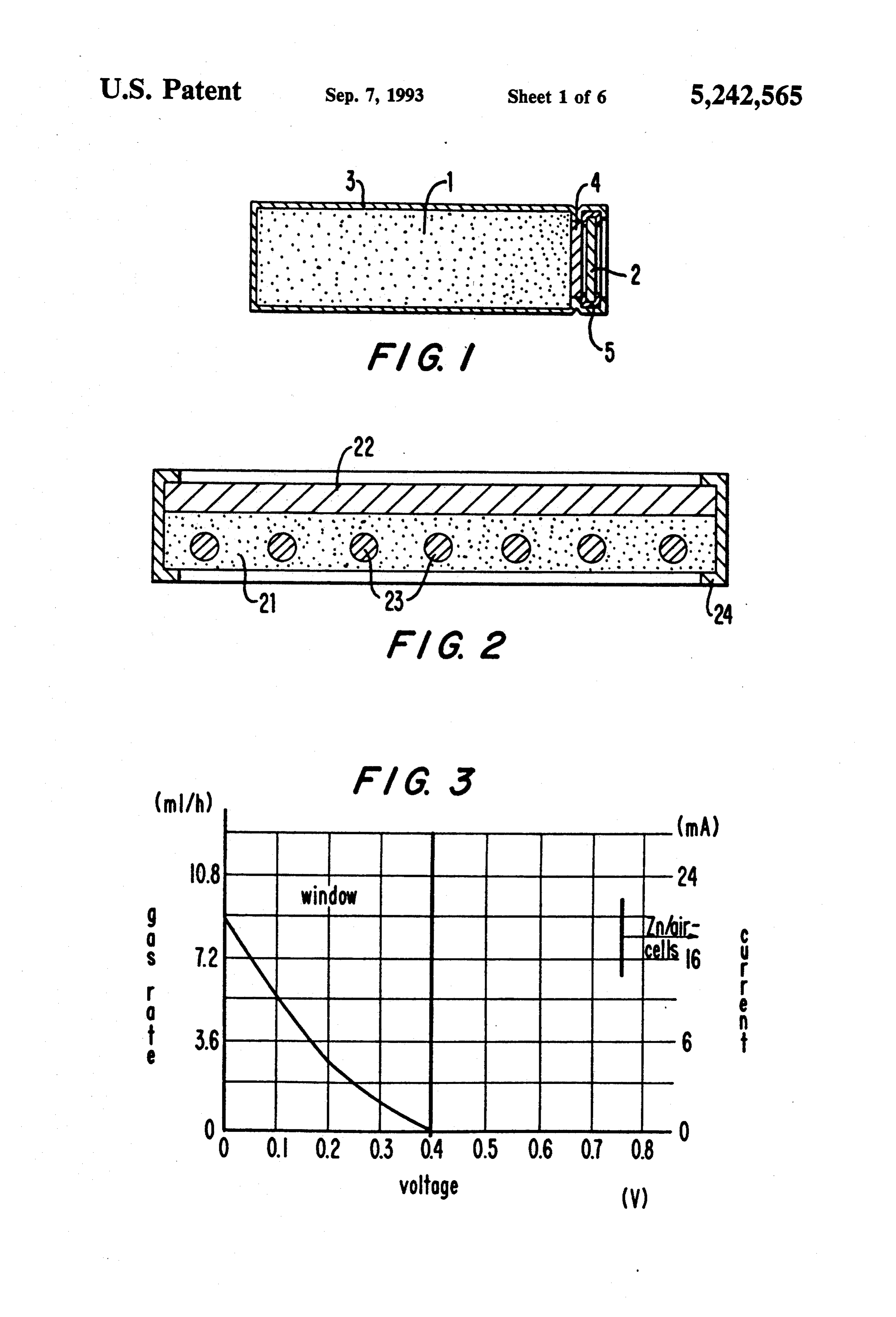
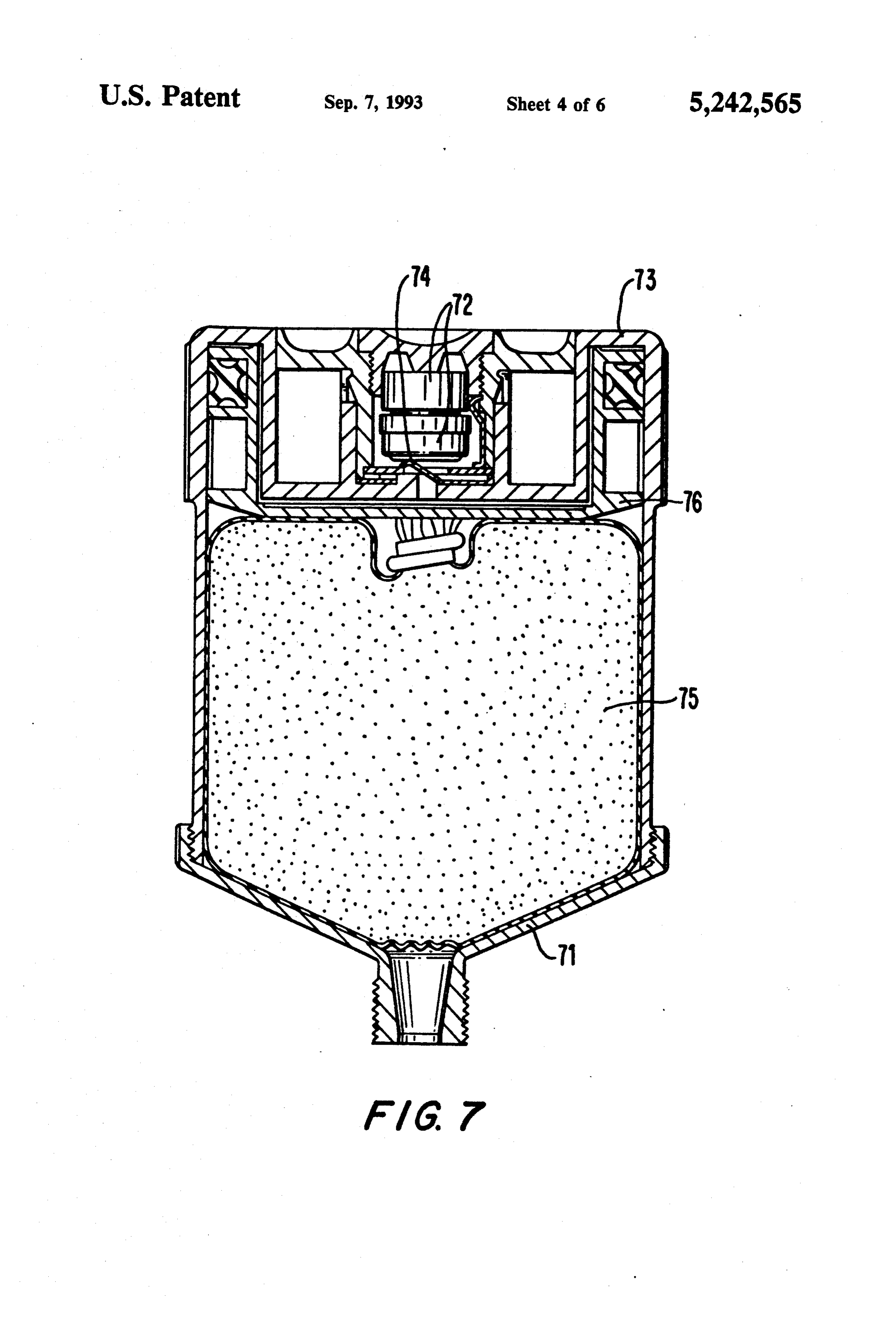
in a lead acid accumulator, the negative electrode is the anode of the cell during discharge of the accumulator, DESCRIPTION OF THE DRAWINGS but it is the cathode during the recharge. Therefore, the FIG. 1 depicts a cross sectional side view of an oxy terms "anode' and "cathode' define the cell and its 15 gen generator cell.
electrodes in a respective function and, thus, are func FIG. 2 depicts a cross sectional view of the structure tional terms depending upon the behavior of the ele of a gas generating electrode according to the present ments. invention.
Within the hydrogen evolving cell of the present FIG. 3 is a graph that illustrates the current/voltage invention, the zinc electrode functions as the anode 20 characteristic of a small hydrogen generator cell. because the OH-anions move to this electrode where they are discharged. The hydrogen evolving electrode torFIG. cells.
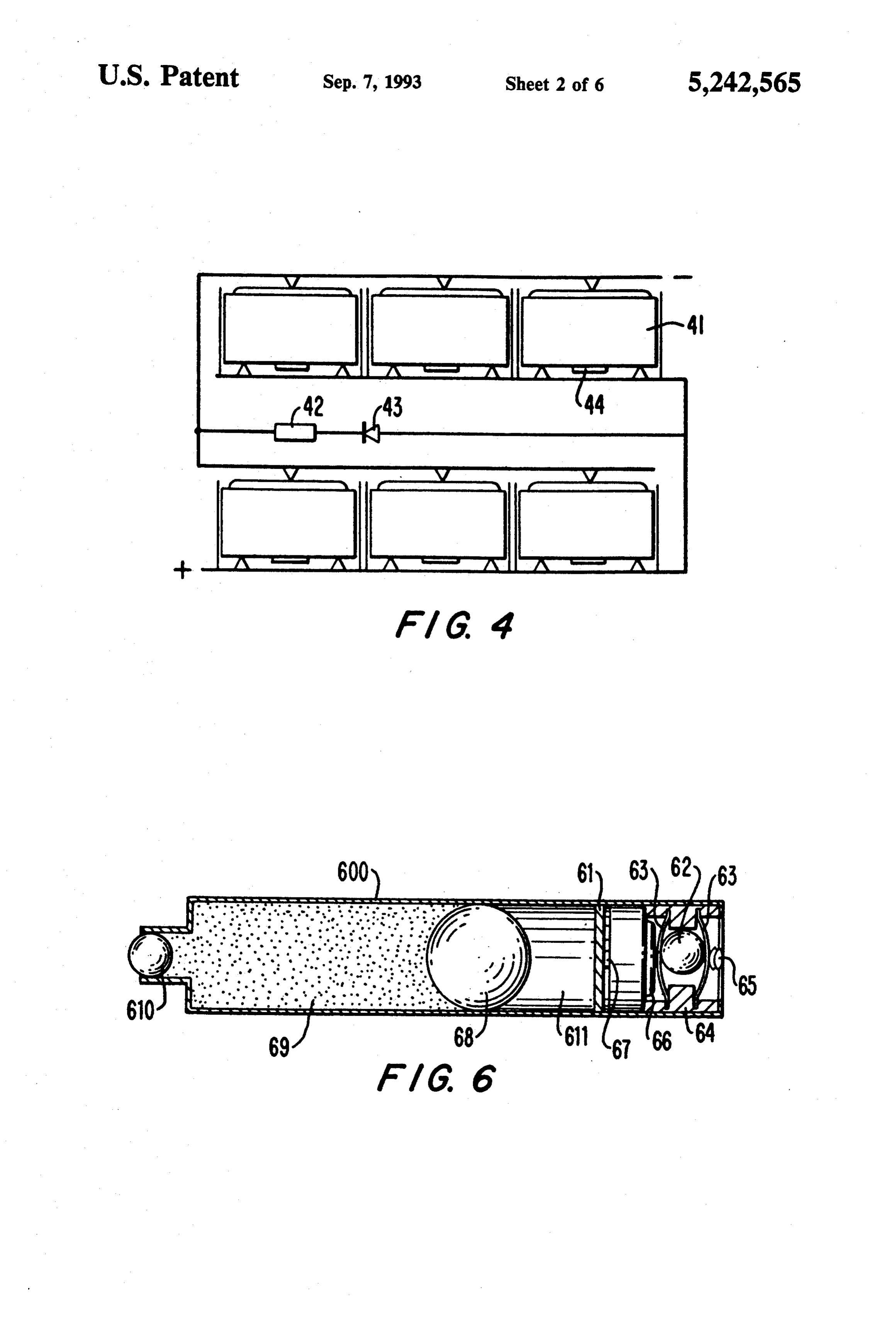
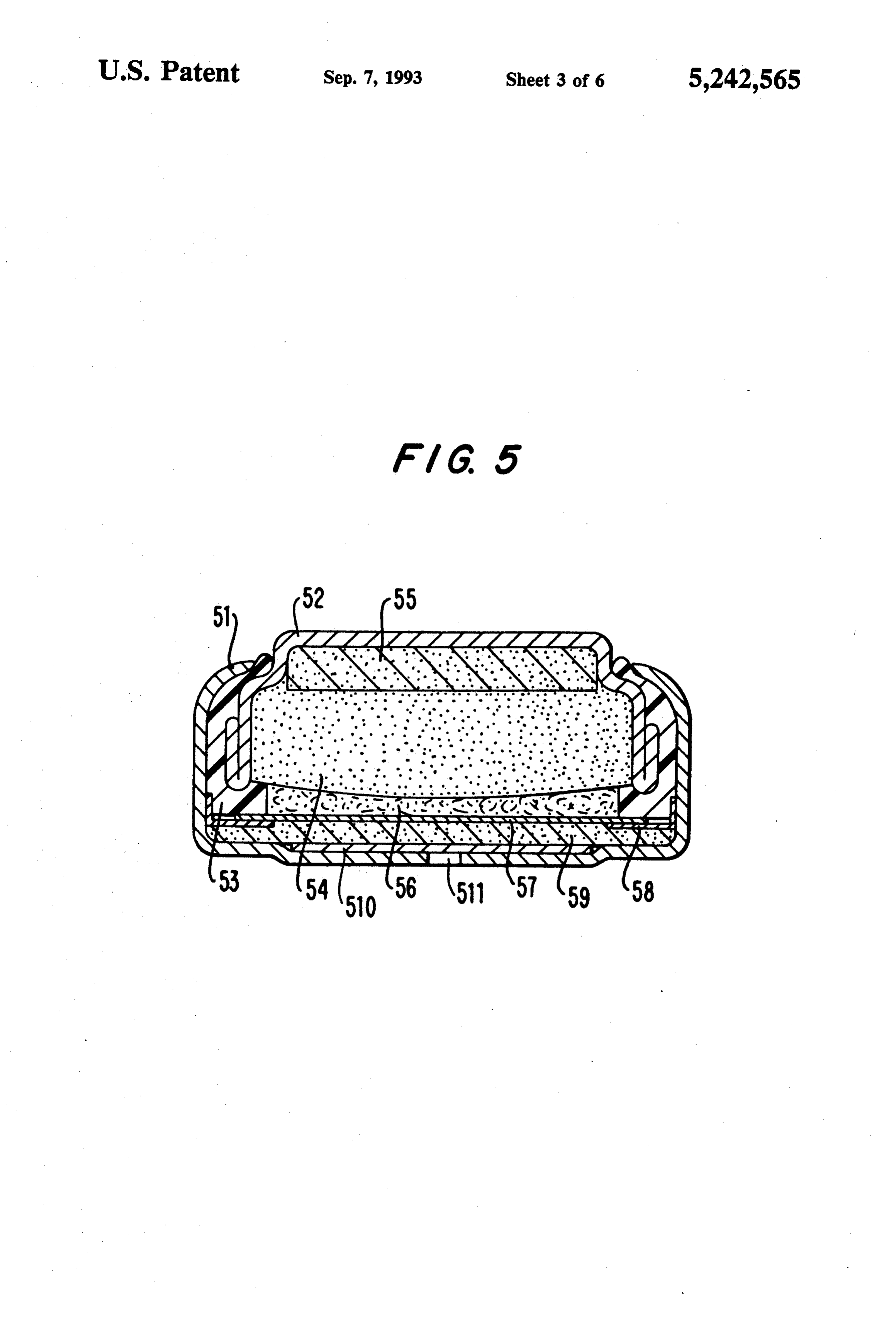
4 depicts an arrangement of hydrogen genera functions as the cathode because the positive H+ cati ons move to this electrode in order to be discharged cellFIG. 5 depicts a cross sectional side view of a button constructed in accordance with the present inven there. 25 tion.
An optionally designed hydrogen evolving cell con FIG. 6 depicts a cross sectional side view of a baro tains a hydrogen evolving electrode (cathode), which statically working roll-on-device. exhibits a hydrogen overvoltage as small as possible.
For this reason, the hydrogen evolving electrode favor cant press depicts
FIG. 7 a cross sectional side view of a lubri containing hydrogen generator cells in series.
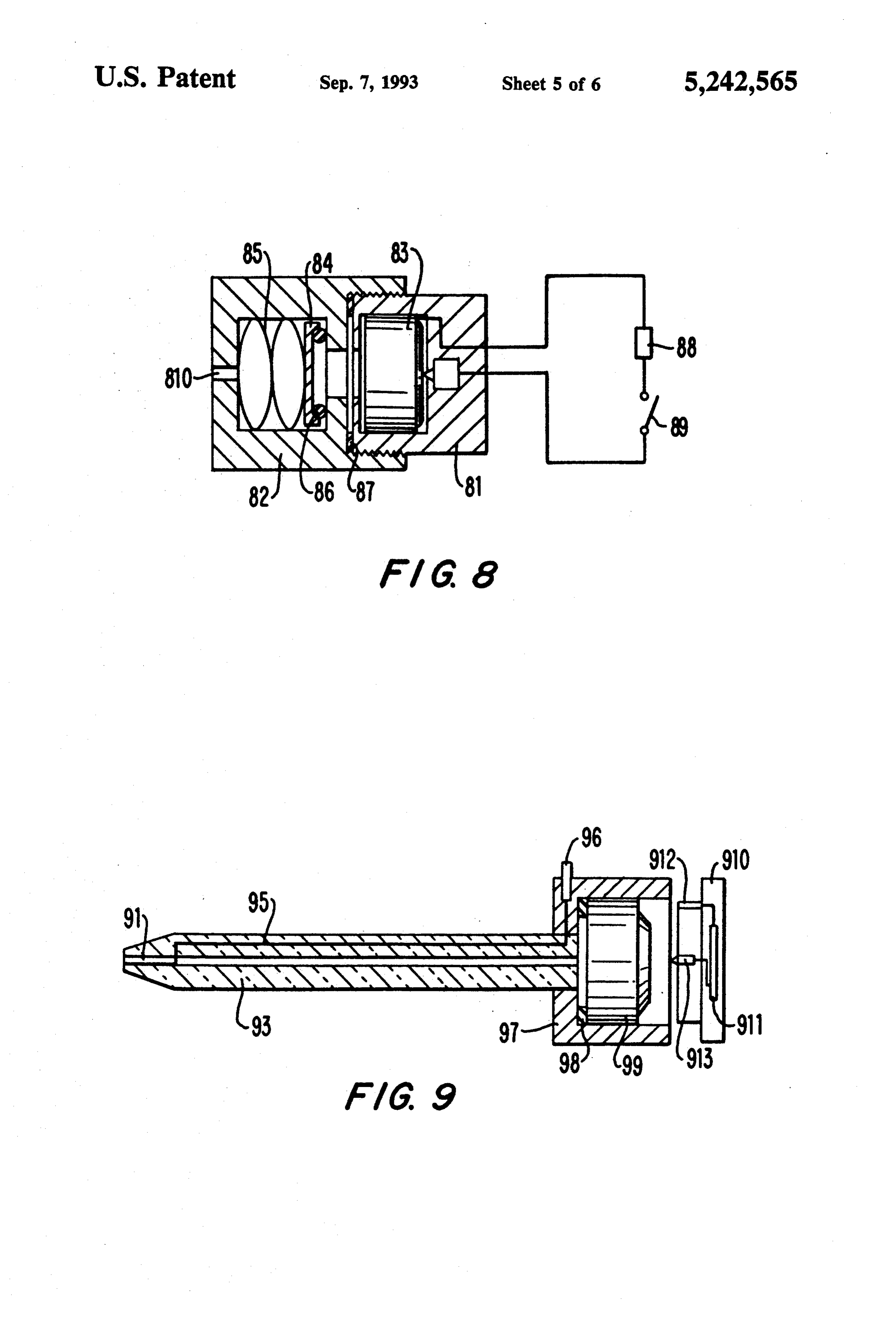
ably contains metals like platinum, palladium or nickel 30 FIG. 8 depicts a cross for example. An optimally designed hydrogen evolving that operates by means ofsectional the side view of a device generating device of the electrode should also have a reduction capacity as small as possible by containing little or no amounts of reduc present invention.
FIG. 9 depicts a cross sectional view of a hydrogen ible metal oxides, because the reduction of such oxides reduces the amount of hydrogen which can be deliv 35 electrode FIGS.
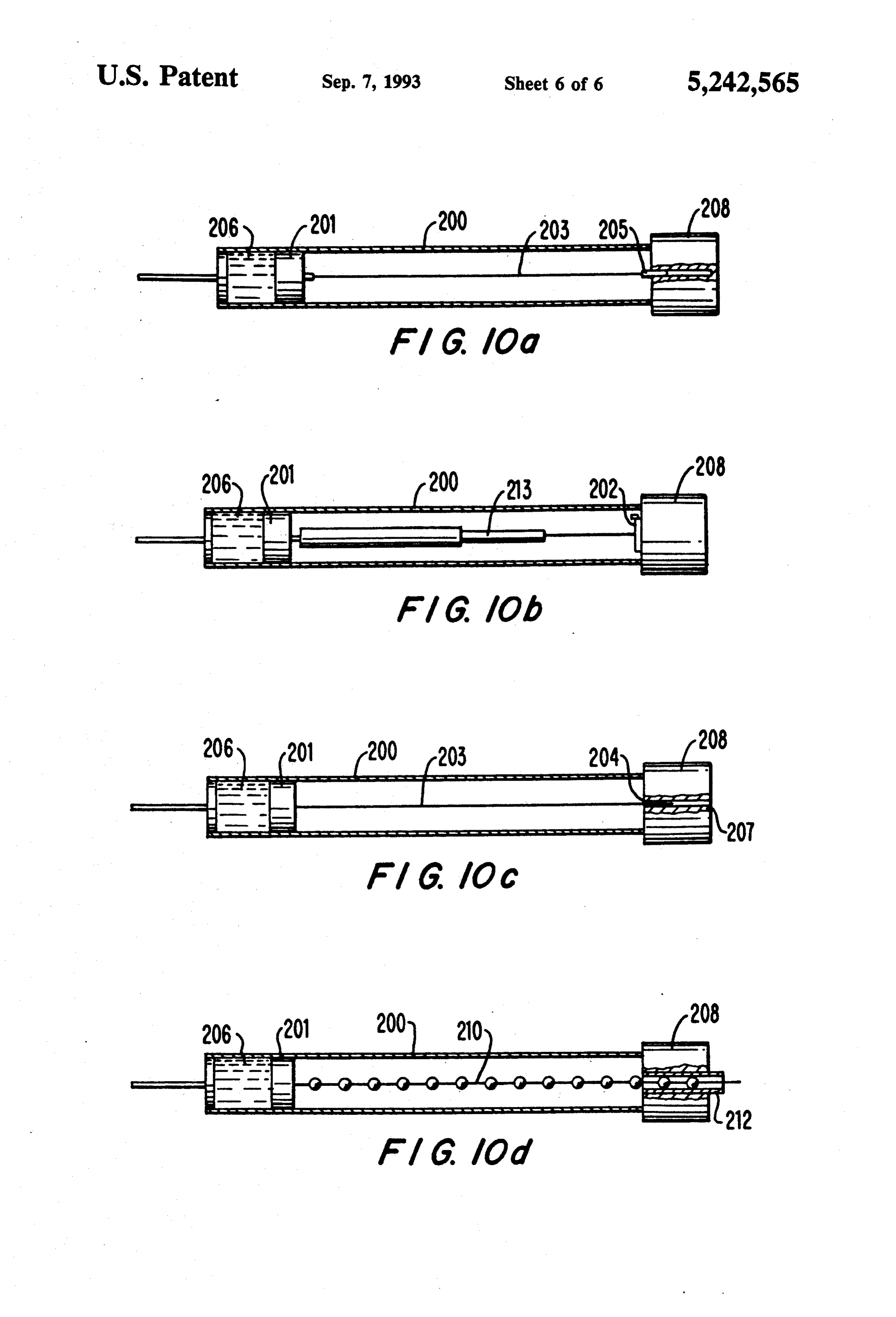
device for electrochemical measurements, 10(a)-(d) depict cross sectional view of em ered by the cell. Further, an optimally designed hydro gen evolving cell contains a maximum volume of liquid bodiments of the present invention that can be used in and solid components at the beginning of the discharge, various applications.
because the volume of these components is reduced by SUMMARY OF THE INVENTION the hydrogen evolving reaction. The device according to the present invention com These demands for a standard hydrogen evolving cell prises a galvanic cell including an anode, a cathode and and its proper design are contrary to those for a zincMair cell. During discharge, the volume of the liquid and an aqueous electrolyte enclosed in a housing (con solid state components of the zincMair cell are increased tainer).
which
The container has one or more openings, by the generated gas is released to the environment.
by the assimilation of the oxygen. Therefore, a reservoir 45 or space area is required within the cell housing in order This objective of the cell, is to generate and release a single gas, thereby defining a new type of cell. The cell to accept the growing volume during discharge.
U.S. Pat. Nos. 4,105,830 to Kordesch and 4,189,526 to ofThe this category is referred to as a "gas generator cell'. gas generator cell of the present invention is
Cretzmeyer both describe "air depolarized' oxygen conveniently described using known electrochemical consuming "zinc air cells' but do not describe cells for 50 terms.
the "evolution' of gases. Due to the teaching of the ably larger than known
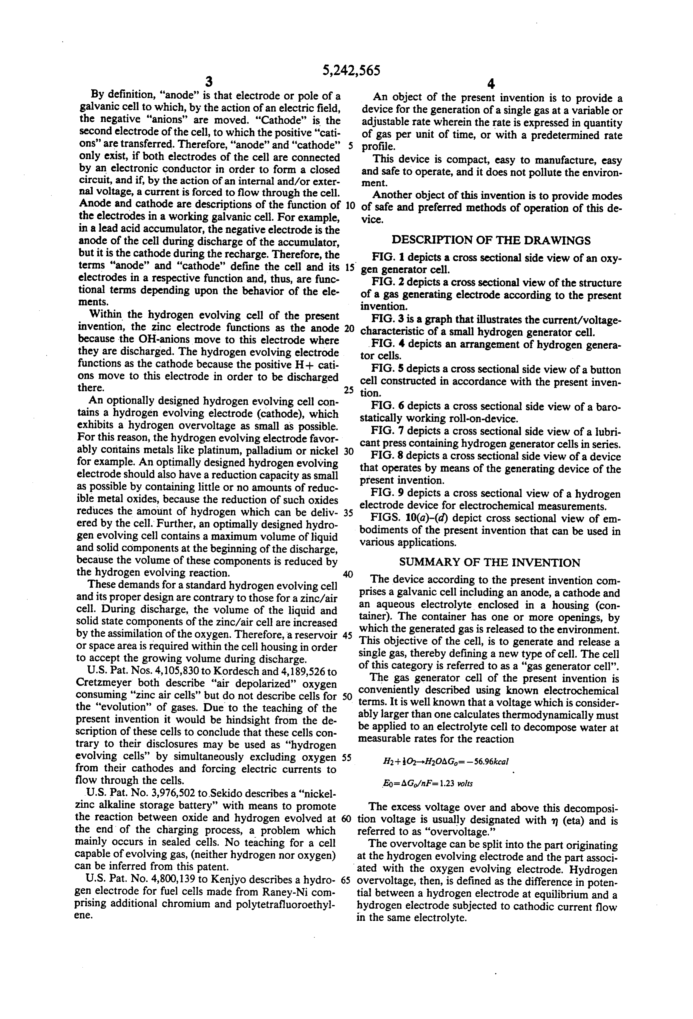
It is well that a voltage which is consider one calculates thermodynamically must present invention it would be hindsight from the de be applied to an electrolyte cell to decompose water at scription of these cells to conclude that these cells con measurable rates for the reaction trary to their disclosures may be used as "hydrogen evolving cells' by simultaneously excluding oxygen 55 H2--O-H2OAG = -56.96kcal from their cathodes and forcing electric currents to flow through the cells. Eo= AG/nF= 1.23 volts U.S. Pat. No. 3,976,502 to Sekido describes a "nickel zinc alkaline storage battery' with means to promote The excess voltage over and above this decomposi the reaction between oxide and hydrogen evolved at tion voltage is usually designated with m (eta) and is the end of the charging process, a problem which referred to as "overvoltage.'
mainly occurs in sealed cells. No teaching for a cell The overvoltage can be split into the part originating capable of evolving gas, (neither hydrogen nor oxygen) at the hydrogen evolving electrode and the part associ can be inferred from this patent. lated with the oxygen evolving electrode. Hydrogen U.S. Pat. No. 4,800,139 to Kenjyo describes a hydro 65 overvoltage, then, is defined as the difference in poten gen electrode for fuel cells made from Raney-Nicom tial between a hydrogen electrode at equilibrium and a prising additional chromium and polytetrafluoroethyl hydrogen electrode subjected to cathodic current flow ele. in the same electrolyte.
Page 10
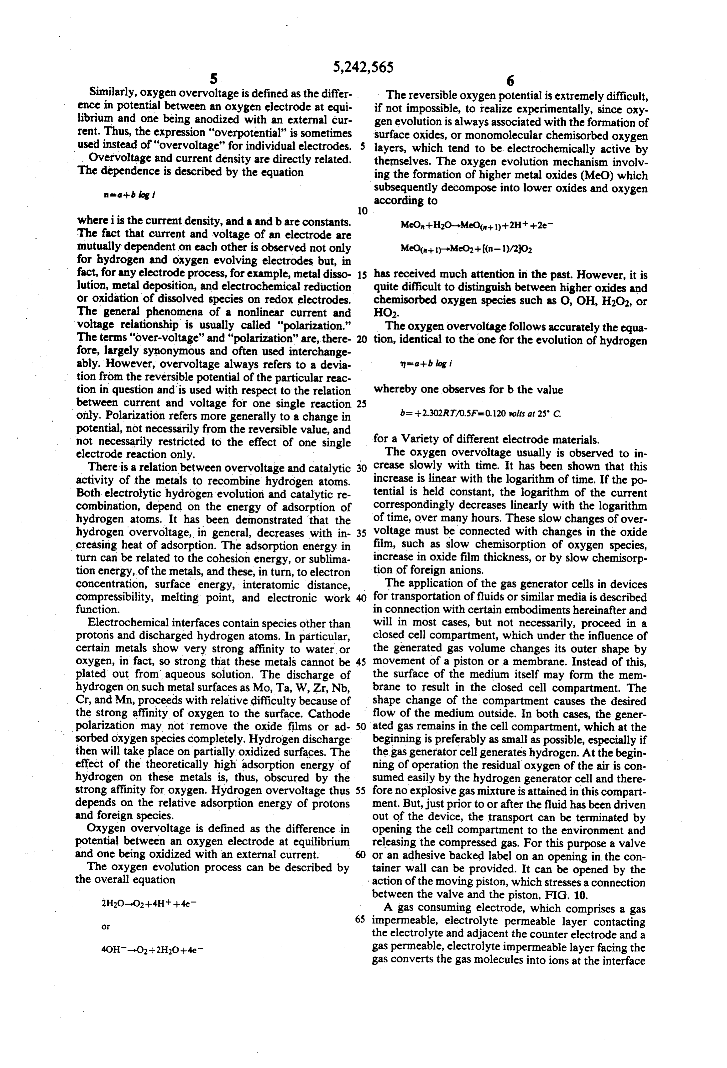
Similarly, oxygen overvoltage is defined as the differ The reversible oxygen potential is extremely difficult, ence in potential between an oxygen electrode at equi if not impossible, to realize experimentally, since oxy librium and one being anodized with an external cur gen evolution is always associated with the formation of rent. Thus, the expression "overpotential" is sometimes surface oxides, or monomolecular chemisorbed oxygen used instead of "overvoltage" for individual electrodes. layers, which tend to be electrochemically active by Overvoltage and current density are directly related. themselves. The oxygen evolution mechanism involv The dependence is described by the equation ing the formation of higher metal oxides (MeO) which nata-blog i subsequently decompose into lower oxides and oxygen according to
where iis the current density, and a and b are constants.
The fact that current and voltage of an electrode are mutually dependent on each other is observed not only for hydrogen and oxygen evolving electrodes but, in fact, for any electrode process, for example, metal disso 15 has received much attention in the past. However, it is lution, metal deposition, and electrochemical reduction quite difficult to distinguish between higher oxides and or oxidation of dissolved species on redox electrodes. chemisorbed oxygen species such as O, OH, H2O2, or The general phenomena of a nonlinear current and HO2.
voltage relationship is usually called "polarization." The oxygen overvoltage follows accurately the equa The terms "over-voltage' and "polarization' are, there 20 tion, identical to the one for the evolution of hydrogen fore, largely synonymous and often used interchange ably. However, overvoltage always refers to a devia tion from the reversible potential of the particular reac tion in question and is used with respect to the relation whereby one observes for b the value between current and voltage for one single reaction 25 b= -2.302RT/0.5F=0.120 wolts at 25 C. only. Polarization refers more generally to a change in potential, not necessarily from the reversible value, and not necessarily restricted to the effect of one single for a Variety of different electrode materials. electrode reaction only. The oxygen overvoltage usually is observed to in There is a relation between overvoltage and catalytic 30 crease slowly with time. It has been shown that this activity of the metals to recombine hydrogen atoms. increase is linear with the logarithm of time. If the po Both electrolytic hydrogen evolution and catalytic re tential is held constant, the logarithm of the current combination, depend on the energy of adsorption of correspondingly decreases linearly with the logarithm hydrogen atoms. It has been demonstrated that the of time, over many hours. These slow changes of over hydrogen overvoltage, in general, decreases with in 35 voltage must be connected with changes in the oxide creasing heat of adsorption. The adsorption energy in film, such as slow chemisorption of oxygen species, turn can be related to the cohesion energy, or sublima increase in oxide film thickness, or by slow chemisorp tion energy, of the metals, and these, in turn, to electron tion of foreign anions.
concentration, surface energy, interatomic distance, The application of the gas generator cells in devices compressibility, melting point, and electronic work for transportation of fluids or similar media is described function. in connection with certain embodiments hereinafter and Electrochemical interfaces contain species other than will in most cases, but not necessarily, proceed in a protons and discharged hydrogen atoms. In particular, closed cell compartment, which under the influence of certain metals show very strong affinity to water or the generated gas volume changes its outer shape by oxygen, in fact, so strong that these metals cannot be 45 movement of a piston or a membrane. Instead of this, plated out from aqueous solution. The discharge of the surface of the medium itself may form the mem hydrogen on such metal surfaces as Mo, Ta, W, Zr, Nb, brane to result in the closed cell compartment. The Cr, and Mn, proceeds with relative difficulty because of shape change of the compartment causes the desired the strong affinity of oxygen to the surface. Cathode flow of the medium outside. In both cases, the gener polarization may not remove the oxide films or ad 50 ated gas remains in the cell compartment, which at the sorbed oxygen species completely. Hydrogen discharge beginning is preferably as small as possible, especially if then will take place on partially oxidized surfaces. The the gas generator cell generates hydrogen. At the begin effect of the theoretically high adsorption energy of ning of operation the residual oxygen of the air is con hydrogen on these metals is, thus, obscured by the sumed easily by the hydrogen generator cell and there strong affinity for oxygen. Hydrogen overvoltage thus 55 fore no explosive gas mixture is attained in this compart depends on the relative adsorption energy of protons ment. But, just prior to or after the fluid has been driven and foreign species. out of the device, the transport can be terminated by Oxygen overvoltage is defined as the difference in opening the cell compartment to the environment and potential between an oxygen electrode at equilibrium releasing the compressed gas. For this purpose a valve and one being oxidized with an external current. 60 or an adhesive backed label on an opening in the con The oxygen evolution process can be described by tainer wall can be provided. It can be opened by the the overall equation action of the moving piston, which stresses a connection between the valve and the piston, FIG. 10.
A gas consuming electrode, which comprises a gas 65 impermeable, electrolyte permeable layer contacting the electrolyte and adjacent the counter electrode and a gas permeable, electrolyte impermeable layer facing the gas converts the gas molecules into ions at the interface
Page 11
of both layers, from where these ions migrate into the layer 21. The metallic frame 24 forms the electronic electrolyte space of the cell. If the current is reversed, contact with the conductor net 23 and permits the elec gas evolution will occur at the interface between elec tronic short circuiting of the cell depicted in FIG. 1. trolyte and electrolyte permeable layer, thus building FIG.3 graphically illustrates an example of the cur up a high inside pressure until the electrolyte permeable rent/voltage-characteristic of a small hydrogen genera electrode layer breaks through. tor cell. The gas rate of the cell as the current is shown It is a feature of the present invention that the work as a function of the cell voltage. The "Window' shows ing layer of the gas evolving electrode consists of two the working range of the zinc based hydrogen genera intersecting cohering pore systems, one of which is tor electrode, and "zincMair-cell' shows the working filled with the electrolyte, the other with the gas by O range of the zincMair-cell.
capillary action. This working layer is laminated with a FIG. 4 depicts the simple arrangement for the condi porous hydrophobic PTFE layer. This construction tioning of zinc based hydrogen generator cells 41. By establishes the lung-like electrochemical transpiration the use of an adhesive backed label 44, the air is main of a gas out of the cell. tained outside of the cell. The rectifying-diode 43 works The reverse process of the electrochemical oxygen 15 like a Zener-diode and stabilizes the voltage of all the consumption is the electrochemical oxygen evolution. cells on the value of its forward voltage. Resistor 42 is In order to optimize the respective evolving reaction, also depicted in the circuit.
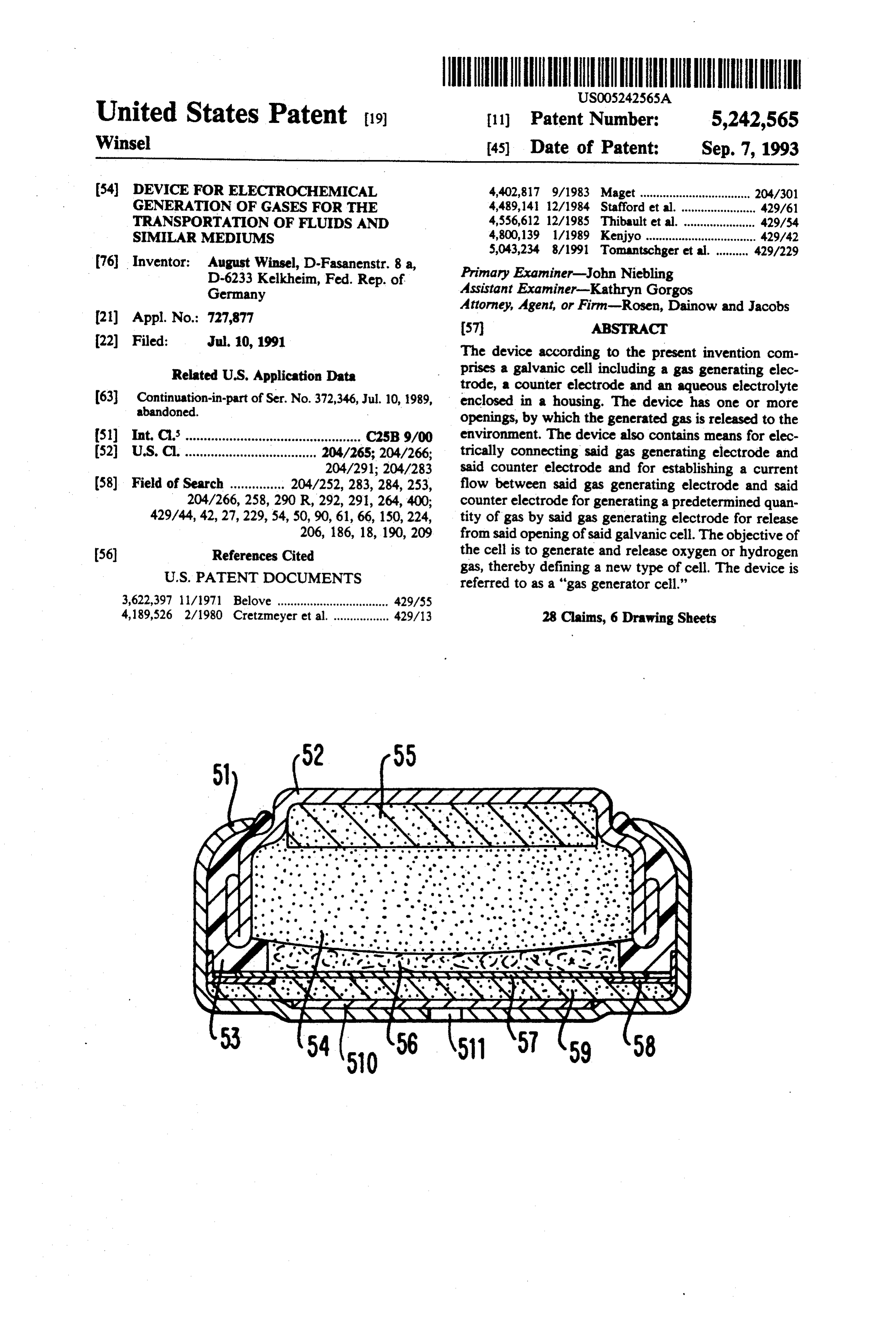
the electrode must be designed for the evolution (not FIG. 5 depicts a cross sectional side view of a button the consumption) of the respective gas. The teaching of cell comprising a cup 51 and a cover 52 which together the proper design of the electrodes to be used in a gas 20 with a plastic seal 53 form the housing wall. Within the evolving cell is part of the instant invention. cover 52 and in contact with it, there is an active sub In an air depolarized cell, the volume and weight of stance 54 in form of a zinc gel containing an electrolyte the material inside the cell is increased during operation, or in form of a porous tablet of a compound such as because the reduced oxygen molecules of the air are manganese dioxide. Compressible porous body 55 may assimilated by the cell. Contrary to this, the volume and 25 contain an additional quantity of electrolyte. Element weight of the active materials in the cell of the present 56 is a fleece impregnated with electrolyte, and 57 is a invention are decreased by the action of the gas evolv separator in the form of an ion-exchange foil. This foil is ing process. The optimal design of a gas evolving cell is kept in position by a support ring 58. An example of a different from that of a gas consuming cell. gas diffusion electrode 59 is made of a Raney-nickel The reaction product of the hydrogen evolving zinc 30 powder bound with PTFE and rolled into a net of cell is zinc oxide. Since it is in contact with the hydro nickel. On the side to the bottom of the cup 51 the gas gen, the zinc oxide cannot be reduced to zinc. There diffusion electrode is provided with a foil of PTFE. fore, the separator between the zinc anode and the hy Metallic support ring 58 is in contact with the gas diffu drogen evolving cathode is not required to be gas im sion electrode 59 and electrically connects the gas diffu permeable. This is in stark contrast to all gas consuming 35 sion electrode 59 with cup 51. Element 510 is a wide cells. There is a clear difference between hydrogen pore fleece layer which channels the gas generated in evolving cells and oxygen evolving cells in this respect. the gas diffusion electrode to opening 511 in the bottom If the gas evolving reaction does not need external of the cup from where it leaves the cell. energy, the reaction product cannot consume the For example, in the instance where zinc is used, due evolved gas without an external energy source. In this to the fact that every zinc atom releases two electrons, case a separator may allow the direct contact of the gas one is thus able to reduce one molecule of water to to the counter electrode. If an additional energy source hydrogen. Accordingly, it is necessary to react in the is required for the gas production from the cell, the gas cell 18 grams of water for every 65 grams of zinc. may be reconsumed by the partly discharged counter FIG. 6 depicts a cross sectional side view of a baro electrode. In this case, a gas impermeable separator, e.g. 45 statically working roll-on-device. Element 61 is a wall, an ion exchange membrane, is necessary. which divides the cylindrical housing 600 of the device DESCRIPTION OF THE PREFERRED into two parts. On one (the right hand) side, there is the EMBODIMENTS zinc based hydrogen generator cell with the positive pole 67 and the negative pole 66. Elements comprising
The invention is exemplified in FIGS. 1-10. 50 63 are two flexible metallized membranes with a ball 62 FIG. 1 depicts a cross sectional side view of an oxy between them. The membranes are fastened in a holder gen generator cell, comprising a cell container 3 for the 64. There is also provided an additional spring 65 which housing of the metal oxide electrode 1, a separator 4, and the oxygen generator electrode 2. Sealing means 5 forces the membrane 63 to contact the minus pole 66 and thereby to shorten the circuit. The generation of prevents the electrolyte from leaking outside of the area 55 gas builds up the pressure inside the device and moves where it is contained and avoids an unintended short circuiting. The gas evolution is started by establishing a membrane 63 to the right hand side of the contact 66. In area 611, ball 68 acts as a piston and presses medium 69, current to flow between the metal container 1 and oxy which can leave the piston via ball valve 610. This gen generator electrode 2. device compensates for the external pressure. In this When cell container 3 is constructed from zinc, the embodiment, a pressure operated switch opens the cir active material 1 is a zinc gel electrode and if 2 is a cuit if a predetermined pressure is exceeded, and the hydrogen generator electrode, this type of cell can switch closes when the pressure drops below predeter deliver large amounts of hydrogen gas. mined value.
FIG. 2 depicts a cross sectional side view of the struc FIG. 7 depicts a cross sectional side view of a solid or ture of a gas generator electrode according to the inven 65 fluid dispenser, more particularly a lubricant press 71 tion. A biporous working layer 21 bears conductor net containing a solid or fluid exemplified by lubricant 75. It 23. This layer 21 is faced to the interior of the cell. is operated by two hydrogen generator cells 72 in series Hydrophobic layer 2 is laminated onto the working connection. Both cells 72 are mounted in potentiometer
Page 12
ring 73, by which potentiometer 74 can be moved into one of the reaction partners. The electrocatalyst re the desired position. The resistance of the potentiometer ferred to is always an electrode because the other reac determines the dispensing rate of the device, that is the tion partner is an ion. A typical electrocatalyst reaction result of movement of piston 76. is:
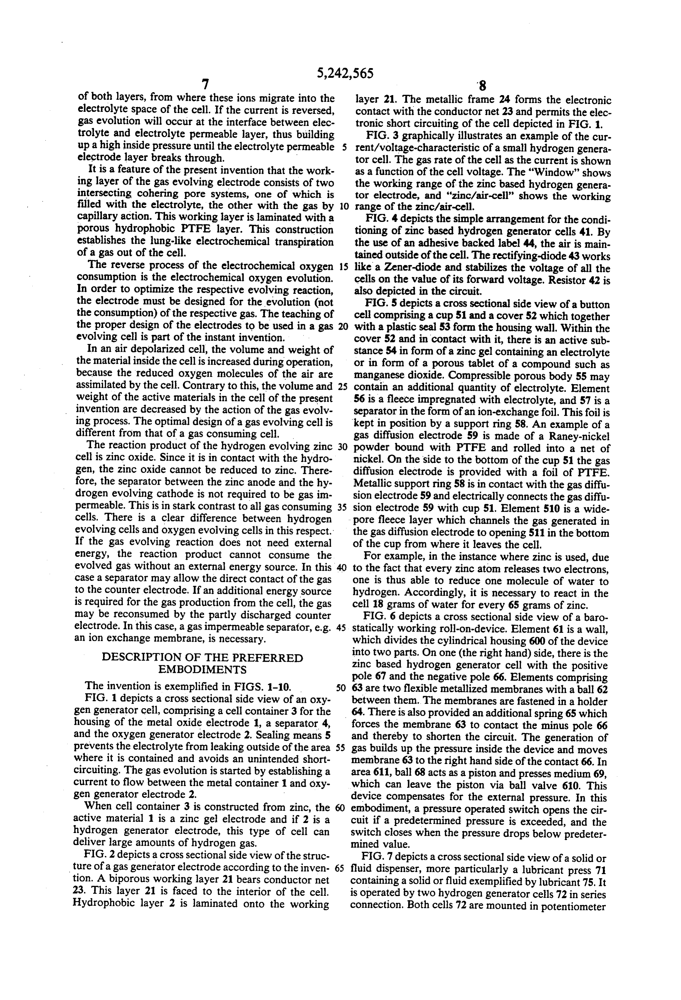
FIG. 8 depicts a cross sectional side view of a device for emitting hydrogen pulses from opening 810 each time the circuit between both poles of gas generator cell 83 has been closed by switch 89 via the outer resistance which is a reaction that only proceeds using some spe 88. The cell 83 is located in and threadedly joined to cial metals such as Pt or metals that are presented in a part 81 of the container 82 with gasket 87 between 10 special structural form such as Raney-Nickel. them. Two springs 85 close the cell compartment by pressing O-ring 86 hold in plate 84 against the housing. useThus, an in the present invention, it is advantageous to electrocatalyst in the biporous working layer 21
The spring force together with the o-ring area deter as shown in FIG.2, which exhibits minimal overvoltage mines the opening pressure of the device. . . (or as small as possible) to the anodic oxygen evolution. FIG.9 depicts a cross sectional side view of a hydro 15 Raney-Nickel powder is a preferred gen electrode device for electrochemical measurements as the electrode in this instance. It material to be used having a platinized platinum wire 91 as a hydrogen desired double porous structure byismixing formed into the it with a electrode. This wire is inserted into the opening of a hydrophobic resin powder such as polytetrafluorethyl tube 93 preferably made of plexiglass or other similar ene (PTFE) or polyethylene (PE). This kind of elec material and is contacted by a wire 95 at contact screw trode has been described earlier by applicant in Euro 96. At the other end, the butt or tube bears cell con pean patent specification EP 144,002 equivalent to the tainer 97 with gasket 98 and hydrogen generator cell 99. German patent application 3342969. Instead of Raney The container is closed by cover 910, which bears Nickel, other powdered contacts 912 and 913 and a potentiometer 911 in order for this purpose, as long catalytic materials can be used as they are stable with respect to generate a sufficient amount of hydrogen for the 25 to the electrolyte. The voltage of the cell depends on hydrogen electrode. Such a hydrogen generator cell can feed the electrode 91 with hydrogen for a substan and type the of metal oxide, on the type of electrocatalyst on the current. However, the rate of the generated tial period of time, for example, more than six months.
More particularly, the invention embodies two types gas is equivalent to the current alone. In case of metal oxides with high oxidation potentials, like AgO and of gas generator cells. The first type as illustrated in 30 NiOOH,
FIG. generates oxygen. It comprises a metal oxide the cell voltage, as a function of the current, counter electrode 1, preferably a metal oxide used in may change its sign (path through zero). For example, primary galvanic cells, e.g. manganese dioxide, silver in the first voltage region, the cell reaction run in the oxide, mercury oxide, and an oxygen generating cata standard manner that cell reactions normally proceed lyst electrode 2. The oxygen generating catalyst elec 35 without an external energy source is necessary for fur trode forms a part of the cell container 3, both together ther operation. Thus as noted, in order to realize a given enveloping the metal oxide electrode 1, a separator 4 rate at a given time, the current is stabilized by the aid and an aqueous electrolyte solution, which preferably is of a direct current source, e.g. a primary battery, and an an alkaline solution. In this "oxygen generator cell' the adjustable resistance.
oxygen generator electrode consists of two layers, as is Alternatively, instead of a metal oxide electrode, shown in FIG. 2. nitrate ions may work as a source of oxygen. In this The following layers are depicted in FIG. 2: case, a metal nitrate or ammonium nitrate as the active i) a working layer 21, comprising an electronically material is cathodically reduced at the counter elec conducting double porous structure. This layer is ex trode, i.e. the second electrode of the galvanic cell posed to and in contact with the separator, the electro 45 which transports the current in combination with the lyte and the metal oxide electrode. The expression other electrode, while oxygen is evolved at the oxygen "double porous" specifies a structure which consists of generator electrode.
two intersecting continuous pore systems, one of which Referring again to FIG. 1, in order to prevent the is hydrophilic and saturated with or by the electrolyte, oxygen from flowing to the metal oxide electrode 1 and the second one is of hydrophobic nature and is filled 50 reoxidizing the reduced oxide, the separator 4 must with gas; form a barrier. Therefore, separator may be an ion ex ii) a porous hydrophobic layer 22 adjacent to and in change membrane or a porous hydrophilic membrane engagement with the working layer. This layer pre with a sufficient capillary pressure in order to avoid gas vents the electrolyte from leaving the cell. filled pores in separator 4. This may not be necessary, if In order to generate oxygen, an electric current is 55 the oxygen gas is non-reactive with the reduced species forced to flow through the oxygen generator cell, of the metal oxide electrode.
which cathodically reduces the metal oxide electrode to The second type of "gas generator cells' of the pres the respective metal or to a minor oxidation state and ent invention as illustrated in FIG. 1 solely generates which anodically develops oxygen at the oxygen gener hydrogen. It provides a metal counter electrode 1, a ator electrode. Due to the unique structure of the oxy "hydrogen generator electrode" 2 and an aqueous elec gen generator electrode, the gas evolves at the three trolyte, preferably an alkaline solution of KOH or phase boundary formed in the hydrophilic pore system NaOH in water. The metal electrode is preferably one of the working layer, penetrates into the hydrophobic of those, which are used in primary or secondary gal pore system of this layer and leaves the cell via the vanic cells, such as zinc, cadmium and lead, but also connected hydrophobic layer. 65 copper can be used. The hydrogen generating catalyst The present invention generally utilizes an electrocat electrode like its counterpart oxygen generating cata alyst which for the purposes of this invention is a cata lyst electrode described above forms a part of the cell lytic material that catalyzes reactions with electrons as container, both together enveloping the metal electrode
Page 13
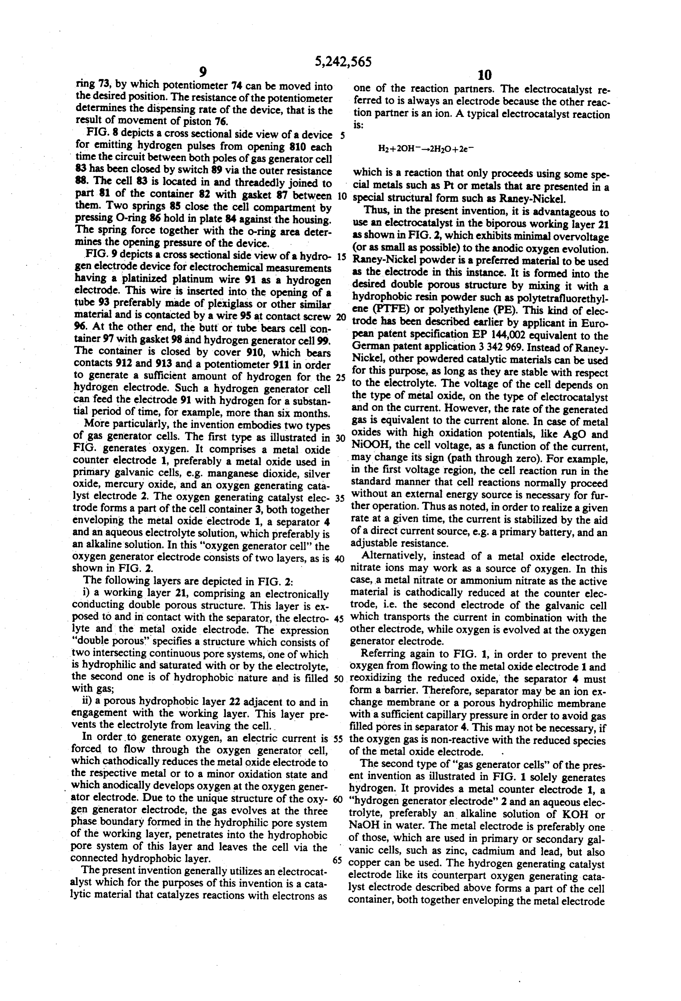
1, the separator 4, and the aqueous electrolyte solution pores of the "hydrogen generator electrode'. There contained therein. fore, air is excluded from the cell by valves for example In this "hydrogen generator cell” the "hydrogen, 84, 86 as shown in FIG. 8 or by adhesive label44 on the generator electrode' consists mainly of two layers. As openings, which are provided in the cell housing as shown in FIG. 2, these layers are: depicted in FIG. 4 to release the generated gas. The i) a working layer 21 comprising an electronically voltage conducting double porous structure; this layer is faced and 0.4 range of operation of the cell is between 0 V to the separator 4 of FIG. 1, to the electrolyte, and to referred to herein as thein "operation V as shown FIG. 3. This voltage range is window." The open the metal electrode 1 of FIG. 1. The term "double po cell voltage of 0.4V to 0.42 V depends rous" or the term "biporous' again specifies a structure, 10 composition and the concentration ofgenerally the on the electrolyte.
which consists of two intersecting continuous pore The current/voltage-characteristic relationship is sub systems, one of which is hydrophilic and saturated with stantially linear if a reversible working electrocatalyst the electrolyte, the second one of which is of hydropho like Pt, Pd or Raney-Nickel is used for the "hydrogen bic nature and is filled with gas:
ii) a porous hydrophobic layer 22 is in close connec 5 generator
voltage of a zinc based hydrogen generator cell tion to biporous working layer 21. This layer 22 pre exceeding 0.5V vents the electrolyte from leaving the cell. In order to prior to the startindicates a malfunction of the cell. But generate hydrogen, an electric current is forced to flow cell voltage very often exceeds by of operation short-circuiting, the through the cell which anodically oxidizes the metal of oxides at the catalyst surface. Thesedue 0.5V can the presence be removed electrode to the respective metal oxide and which ca 20 thodically develops hydrogen at the hydrogen genera by conditioning the cell at 0.5 V to 0.7 V. A simple tor electrode. Due to the unique structure of the "hy method can be realized by short-circuiting the cell via a rectifying diode in flux direction as shown in FIG. 4.
drogen generator electrode", the gas evolves at the This reduces all deleterious oxygen containing species three phase boundary gas/electrolyte/catalyst, formed in the hydrophilic pore system of working layer 21. The 25 on the gas generator electrode without evolving any gas then penetrates into the hydrophobic pore system of hydrogen.
this layer and leaves the cell via the connected hydro If a hydrogen generator cell with zinc as metal elec phobic layer 22. trode is discharged in air or in a oxygen-rich environ It is advantageous to use an electrocatalyst in work ment, the voltage will remain above 0.8 V, but the cell ing layer 21, which offers a small overvoltage to the 30 will produce no hydrogen. In this instance, the cell cathodic hydrogen evolution. Raney-Nickel powder is works as a zincMair cell as long as enough space is avail a preferred material. It is formed into the desired double able inside the cell housing to retain the assimilated porous structure by mixing it with a hydrophobic resin oxygen. If oxygen is excluded from a zincMair cell of the powder such as polytetrafluorethylene (PTFE) or poly common construction, and if this cell is short-circuited ethylene (PE) as described above and found in Euro 35 and if the cell voltage is allowed to fall below 0.4 V, this pean patent specification EP 144,002. Instead of Raney cell may evolve hydrogen, too. Thus, a gas consuming Nickel, other powdered catalytic materials can be used zinc./air cell is forced to operate as a "hydrogen genera for this purpose, which are stable against and will not be tor cell'. A zincMair cell is a gas consuming cell; oxygen oxidized nor reduced by the electrolyte. A very suitable is an essential part of the cell and of its overall reaction. material for this use is platinized or palladinized active By contrast, "hydrogen generator cell' of the present carbon powder. Also, an active carbon/Raney-Nickel invention produces hydrogen, which is a product but mixture can be used economically. not an essential component of the cell. From these con The voltage of the cell depends on the type of metal, siderations it follows: Although the zinc-based hydro on the type of electrocatalyst and on the current. How gen generator cell of the present invention and a com ever, the rate of the generated gas i.e. (amount of gas) 45 mon zinc-air cell appear similar in some details of con generated per unit of time) is equivalent to the current struction, they show no equivalence because oxygen alone. has to be excluded from the interior of the hydrogen Besides the use of Raney-Nickel, other Raney-metals generator cell, but is an essential part of the zinc/air of Group VIII of the periodic table of elements exhibit cell. Zinc/air cell and the zinc based hydrogen genera zero or very small hydrogen overvoltage. Therefore, SO tor cell operate with substantially different voltage the internal resistance in the circuit as a function of the windows.
current is nearly constant. In order to realize a given An optimal designed hydrogen generator cell as rate of gas generation for a given time period, the cur shown in FIG. 1 and FIG. 5 contains a hydrogen gener rent can be stabilized by the aid of a direct current ator electrode, which exhibits a hydrogen overvoltage source, e.g. a primary battery, and an adjustable resis 55 as low as possible. For this reason, the hydrogen evolv tance. ing electrode contains metals like platinum or palla In the course of this invention, zinc has proved to be dium. Alternatively, nickel, which is favored due to its the most suitable metal electrode for "hydrogen genera low price can also be used. In addition, an optimal de tor cells.'Like in primary battery applications, it can be signed hydrogen generator electrode should exhibit a used in the form of a sheet zinc metal, as a pressed zinc reduction capacity as small as possible and, therefore, powder electrode or as a so called "zinc gel electrode'. should contain only small amounts of reducible metal A zinc sheet may form the cylindrically shaped cell oxides because the reduction of such oxides reduces the housing as depicted in FIG. 1 containing within a zinc amount of hydrogen, which can be delivered by the powder electrode or a zinc gel electrode and the other cell. An optimal designed hydrogen generator cell con components of the cell. In its most simple application, 65 tains a maximum of water and zinc at the beginning of the hydrogen generator cell with a zinc electrode does the discharge, zinc and water in such a ratio, as to give not need any external power source. In order to allow a maximum of hydrogen according to the equation its proper operation, oxygen must be excluded from the Zn-i-H2O-ZnO-H2.
Page 14
The quantity of zinc and electrolyte, which have to back to the zinc electrode, no reaction can take place be filled in into such housing, are depending on the . which can reduce the amount of the gas released by the quantity of hydrogen to be produced by the cell. For a cell.
production of 1 dm3 of hydrogen, roughly 0.32 g Zn and In principle, an oxygen generator cell looks like the 0.80g H2O are needed. The magnitude of the gas gener hydrogen generator cell depicted in FIG. 5. In this case, ator electrode only depends on the rate of gas evolu the cell contains reducible metal oxide electrode 54 and tion. For example, a rate of 0.04 Ndm/h of hydrogen oxygen generator electrode 59. In some cases, the sepa corresponds to a current of 100 mA; for this current an rator 56 of an oxygen generator cell has to prevent the electrode surface of 1 cm2 is sufficient. In order to gen generated oxygen from flowing back to the cathode 54, erate as much gas as possible using a gas generator cell O because the oxygen might be reconsumed by the re of given internal space, the cell should contain as much duced parts of the cathode material. In this embodi reducible metal oxide as possible in case of an oxygen ment, an ion exchange membrane would be optimal for generator cell and, respectively as much oxidizable the separator.
metal as possible in case of an hydrogen generator cell. It is possible to operate the gas generator cell in a During discharge of the cell FIG. 5, the volume of 15 barostatic mode. This can be done by using a pressure the internal components is reduced by the release of the operated switch to open the circuit when a predeter hydrogen gas. The same behavior of decreasing volume mined pressure is attained. This is shown in FIG. 6. is true for the oxygen generator cell. To maintain For short intervals of time, it is possible to operate a contact between the solid and liquid phases involved in hydrogen generator cell in a hydrogen consuming the respective reaction, the electrolyte may be pressur 20 mode by increasing the voltage in the presence of hy ized, which can be done by introducing it with small drogen slightly above 0.4V while reversing the current. over pressure into the wide pores of a hydrophobic Current reversal leads to an electrode position of zinc at body 55 or by using hydrophilic absorbent paper 56 in the zinc electrode and to an electrochemical consump the important areas. It is also possible to maintain tion of hydrogen. This reversal mode of operation can contact between zinc electrode 54, the respective con 25 be used to reduce the pressure in the hydrogen driven ductor 52 and the separator 56 by means of a spring device, if necessary. This might be of benefit, if a per elements for example a sponge 55. The separator is son, who is carrying a gas driven inject, is climbing on hydrophilic and is arranged between the zinc electrode a tall mountain or is flying in a jet liner. But for this 54 and the gas generator electrode (that is between the mode of reverse operation, an additional power source counter electrode and the gas generator electrode). 30 is required.
Finally, it is possible to effect a change of volume It is possible to use a number of gas generator cells in from outside by deformation of the cell housing. These series connection. At the same current density, the volt parameters for a hydrogen generator cell and its proper age of the battery is n-times that of a single cell, and the design are contrary to those for a zinc/air-cell. During generated rate of gas is n-times that of a single cell, discharge, the volume of the liquid and solid state com 35 In order to operate a gas driven device at a constant ponents of the cell is increased by the assimilation of the rate, only a constant ohmic resistance is needed to oxygen. Therefore, during construction, empty space is short-circuit the zinc based hydrogen generator cell. left in the cell housing in order to absorb the growing But in order to quickly attain this state of operation, it is volume during discharge. advantageous to start the generator cell by short-cir It is a teaching of this invention, that a hydrogen cuiting with a very small ohmic resistance and switch evolving cell will function as a zincMair-cell, if air is over to the final one later on.
allowed to penetrate into the pores of the gas generator If pulses of hydrogen are needed from time to time, it electrode. In this case, no hydrogen is released by the is useful to pulse the current by closing and opening an cell. The reason for this is the large reactivity of the electric switch as shown in FIG. 8. The generated hy oxygen, which reacts in contact with all electrochemi 45 drogen quickly raises the pressure inside the cell, which cal metals. It is also a teaching of this invention, that a is shunted against the device by an over pressure-valve. "zinc-air cell' can release hydrogen, if air is excluded This valve opens after the electric switch has short-cir from the cell and the cell is operated below 0.4 V. cuited the cell and the pressure has risen a predeter Therefore, another embodiment of the present inven mined value. When the switch opens, the pressure again tion is in alteration of the intrinsic objective, certain SO falls under the closing pressure of the valve and so on. types of so called zinc/air cells may be used as hydro The following examples show useful applications, gen evolving cells if oxygen is excluded from the cath which are based upon the new gas generator cells. ode, and an electric current is enabled to flow through As shown in FIG. 7, a lubricant-press contains a the cell at a voltage below 0.4 V. The current is enabled piston 76 in a closed cylinder 71, which separates the to flow by an electronic circuit, which shortens both 55 lubricant-compartment 75 from the pressure-compart electrodes of the cell. A zincMair cell, from which air is ment. The gas generator cells 72 according to the inven excluded is in reality not a zincMair cell since it does not tion are arranged within the compression compartment, contain an air cathode due to the lack of oxygen. e.g. in the endplate of this compartment. At the other Some additional details of preferred applications of end of the press, there is a mouth-piece to connect the the present invention are described in FIG. 5 of the 60 press with the ball-bearing. If the gas generator cell is a drawings. In FIG. 5, a zinc-based hydrogen generator zinc based hydrogen generator cell, the activation of cell is shown. The cell is designed as a button cell hav the press can easily be done by short-circuiting the cell ing cup 51, with a cover 52 of the cell housing gasket 53, with a potentiometer 74, which of advantage is situated zinc anode 54, electrolyte sponge 55, 56 is a fleece, inside the pressure room but can be regulated by a porous separator or an unporous ion exchange mem 65 screw or by potentiometer ring 73 from outside the brane 57, hard ring 58, hydrogen generator electrode press.
59. Additionally, paper-like fleece 510 and opening 511 FIGS. 10(a) through (d) disclose various uses for the are provided to release the gas. If hydrogen diffuses cell of the present invention. In an injection device for
Page 15
medical purposes, a piston or a membrane is dividing So long as the piston has not arrived at its desired end the cylindrical compartment in two parts, one of which position, the hole remains closed. But if the end of contains the injection, the second one contains the gas thread 203 has moved through the hole 204, the valve is generator cell and the expanding gas. In case of the open and the gas is released to the environment as de zinc-based hydrogen generator cell, only one resistance scribed before.
in order to short-circuit the cell is needed for a nearly The construction depicted in FIG. 10(d) is called a constant injection rate of the medicine. A button cell of "rosary valve' and comprises a chain of balls 210 of about 10 mm in diameter and 5 mm in height is a suffi limited length. At one end it is fixed to the moving cient for an injection of 20 ml within 10 h. In this appli piston 201. This rosary chain 210 is towed through a cation, the cell is mounted preferably on top of the 10 narrow elastic pipe 212 long enough to have always two injectee. By addition of a regulator circuit for the gener balls inside the pipe 212. If as a result of the movement ator current, the injection rate can be adapted to a given of piston 201 the last ball has passed through pipe 212, profile. this valve is open. The compressed gas can escape to the Also, hydrogen electrodes are frequently used in environment and air can enter cylinder 200. order to measure the pH-value of aqueous solutions of 5 The electrical circuit means depicted in FIGS. 10 (a) salts, acids or bases. The hydrogen electrode consisting through (d) all act on the gas generator cell, either by generally of a Pt-wire, which is encircled by hydrogen, interrupting the current or by promoting a malfunction. is dipped into the solution which is to be measured for In case of FIG. 10(a) and (b), a force of the moving acidity or basicity. The problem is such an electrode is piston only acts in the very last moment of its move the need for a hydrogen source, which in general is ment. This is in contrast to FIGS. 10(c) and (d). In these contained in a heavy steel pressurized gas bottle. In embodiments, the force acts as long as the piston moves FIG.9, a device is shown, which consists of a hydrogen but falls to zero when the end of the thread 203 or the electrode at one end of a narrow pipe. At the other end, chain 210 has moved through the valve. there is a hydrogen generator cell, which feeds the The diameter of thread 203 may be smaller after the electrode with the hydrogen gas under the pressure 25 desired length has moved through hole 204. In this case, needed for this purpose. the desired function of thread 203 in FIG. 10(c) is still FIGS. 10 (a) through (d) show cross sectional views guaranteed. The same is true for rosary chain 210, of a fluid dispensing device according to the invention which may end in a ball-free thread with a finger slip with different means for terminating and eventually knot. Such an elongated thread has the advantage of controlling the dispensing process. In applications of 30 pulling the piston in the reverse direction in order to the present invention in the field of medicine, it is im recharge the device with the fluid 206. portant that the continuous generation of gas by the gas These illustrative examples, provide evidence for generator cell 208 be stopped immediately at the end of useful applications of the gas generator electrode. These the dispensing process. This is necessary to prevent an examples under appropriate modification can be con entry of the hydrogen gas into the human body due to 35 verted to oxygen generator cells.
an uncontrolled increase of the pressure. In FIGS. 10(a) What I claim and desire to protect by Letters Patent through (d), cylinder 200 contains the piston 201, which 1S:
is driven to the left hand side by the gas generated in 1. A device for electrochemically generating a hydro cell container 208. As indicated in FIG.10(b), container gen gas or an oxygen gas in an adjustable quantity, 208 contains the cell, the resistor, the switch 202 and 40 comprising:
other construction elements, which are necessary or of a galvanic cell including an enclosed housing having advantage to make use of the invention but need not to a base and at least one side wall integral with said be shown in this particular case. The gas generated by base, a cover, a seal positioned between and in the cell 208 is lead into cylinder 200, thereby driving the contact with said cover and said side wall of said piston 201 to the left hand side and dispensing fluid 206 45 housing, and an opening for releasing gas from said into the body. During this process, the plug 205 closes housing, said galvanic cell further including; the valve. Piston 201 and plug 205 are connected by a a gas generating electrode forming a part of said line or thread 203 or a telescope 213 of a given length. housing and including an electron-conducting When piston 201 reaches its destinated end position, porous body contained within said housing; thread 203 or telescope 213 are stretched. The force 50 a counter electrode including an oxidizable metal which has driven the piston 201 so far now acts on the or a reducible oxide or nitrate which serves in plug 205 and opens the valve in FIG. 10(a), or it acts by countercapacity to said gas generating electrode; telescope 213 on switch 202. Switch 202 is opened and separator means between said gas generating elec the cell current in FIG, 10(b) is interrupted. trode and said counter electrode; and When valve 205 in FIG. 10(a) is opened the com 55 an alkaline electrolyte present in an amount suffi pressed gas in cylinder 200 is released to the environ cient to provide reactions, in said gas generating ment and air enters cylinder 200. In case of the most electrode and in said counter electrode; and frequently used zinc based hydrogen generator cell, the means for electrically connecting said gas generat voltage of the cell indicates this as a “malfunction'. The ing electrode and said counter electrode, and voltage sharply increases to more than 0.8 V and the means for supplying a current flow between said hydrogen generation immediately stops. The result is gas generating electrode and said counter elec merely the same as in the case of switching off the short trode for generating a predetermined quantity of circuit in FIG. 10(b), but both methods can be com gas by said gas generating electrode, for release bined, too. from said opening of said galvanic cell. In a very simple construction as depicted in FIG. 65 2. An actuating apparatus for means for dispensing 10(c), the valve consists of a non porous thread 203 solids and fluids, or transporting mediums, including the which is stressed by the action of the piston to move device defined in claim 1, which also possesses means through a narrow hole 204 of a rubber-elastic plate 207. connecting said opening of said galvanic cell and said
Page 16
dispensing means or said transporting medium, for sup electrode forming a part of said housing includes a hy plying gas to said actuating apparatus for operating said drophilic, electrolyte-receiving portion and a hydro dispensing means or said transporting medium. phobic, gas-receiving portion, and a porous hydropho 3. The device defined in claim 2 wherein an electrical bic layer adjacent to and in engagement with said po circuit and adjustable resistance is provided to control rous body, for preventing electrolyte from leaving the gas generation. galvanic cell;
4. The device defined in claim 2 containing means to and wherein said counter electrode includes an oxi open the circuit provided by direct current upon reach dizable metal which serves in countercapacity to ing a predetermined gas pressure and to close said cir said gas generating electrode; cuit when said gas pressure falls below a predetermined 10 and includes means for excluding air from said gal value.
5. The device defined in claim 2 that releases the vanic cell, and for excluding oxygen from the pores generated gas in pulses. of the gas generating electrode. 6. The actuating apparatus defined in claim 2 wherein dizable14. The device defined in claim 13 wherein said oxi said means includes a barostatically operated device 15 zinc, calcium,metal is selected from the group consisting of containing a pressure operated switch that opens an lead and copper. 15. The device electrical circuit contained with said system when a dizable metal is zinc defined in claim 14 wherein said oxi predetermined pressure is reached and closes when the operates at a voltage of powder or zinc gel and said cell pressure drops below a predetermined value. about 0.4 V or less. 7. The actuating apparatus defined in claim 2 wherein 20 16. The device defined in claim 15 wherein said zinc said means includes external electrical circuit which sealingcell is short circuited via low resistance and contains connects said device with a container that emits gas when said means to prevent entrance of air into said cell cell starts generating gas to actuate said pulses from an opening in said container, said container means for dispensing interiorly having a plurality of springs adjacent one or transporting. 17. The device defined in claim 15 wherein said oxi another and means in concert with said springs to seal 25 dizable off an opening in said device from the container at the metal is zinc gel containing said electrolyte is location where said device and container are connected, situated within said housing. the emission of a gas pulse from said opening in said 18. The device of claim 13 wherein said porous body container being the result of the completion of the elec of said gas generating electrode comprises a metal from trical circuit that includes said device. 30 Group VIII of the Periodic Table of elements selected 8. The apparatus having means defined in claim 2 for from the group consisting of platinum, palladium and taking electrochemical measurements in working com nickel, alone or in combination with carbon, said metals bination with a nonreactive tube having an opening at having low overvoltage with respect to the evolution of one end, and having a hydrogen electrode that is in the gas at said electrode.
serted into an open end of said nonreactive tube, the 35 19. The device defined in claim 1 for generating oxy device that generates said hydrogen gas being secured gen gas in an adjustable quantity wherein said electron to said tube at the other end thereof. conducting porous body of said gas generating elec 9. The apparatus including means defined in claim 2 trode forming a part of said housing includes a hydro for dispensing fluid in working combination with a philic, electrolyte-receiving portion and a hydrophobic, container comprising a cylinder having a movable pis 40 gas-receiving portion, and a porous hydrophobic layer ton located therein, means connecting said piston at one adjacent to and in engagement with said porous body, end to a valve located at the opening through the end of for preventing electrolyte from leaving the galvanic said cylinder at the other end of said means, wherein as cell;
the said piston in said cylinder moves away from said and said counter electrode includes a reducible oxide valve, said connecting means causes said valve to open 45 which serves in countercapacity to said gas gener and releases hydrogen produced by said device into the ating electrode; and atmosphere. means for electrically connecting said gas generating 10. The apparatus defined in claim 9 wherein the electrode and said counter electrode, and for estab connecting means is attached at one end to an electric lishing a current flow between said gas generating switch. 50 electrode and said counter electrode for generating 11. The apparatus defined in claim 10 wherein the a predetermined quantity of gas by said gas gener valve comprises a non porous thread that moves in an ating electrode, for release from said opening of opening through a plate fixed at the end of said cylinder said galvanic cell.
adjacent said cell, thus forming a valve to the atmo 20. The device defined in claim 19 wherein said re sphere which is closed as long as said non porous thread 55 ducible oxide is selected from the group consisting of has not moved through said opening. manganese dioxide, silver oxide, mercury oxide and 12. The apparatus defined n claim 10 wherein said nickel oxide.
connecting means comprises a plurality of balls at 21. The device defined in claim 20 wherein the said tached to a wire forming a chain, said chain being capa reducible oxide is in the form of a porous tablet of a ble of moving through an elastic pipe situated at the end manganese dioxide and is situated within said housing. of said cylinder adjacent said cell, the length of said pipe 22. The device defined in claim 19 wherein said re being sufficient to contain two balls of the chain therein ducible oxide is selected from the group consisting of to seal off said pipe, said balls forming a valve like ac nitrate is ammonium nitrate.
tion in said pipe, the valve being opened when the last 23. The device defined in claim 22 wherein charcoal ball of said chain has passed through said pipe. 65 powder is blended with said Raney nickel powder. 13. The device defined in claim 1 for generating hy 24. The device defined in claim 22 wherein said gas drogen gas in an adjustable quantity wherein said elec generating electrode generates oxygen gas and com tron-conducting porous body of said gas generating prises Raney nickel powder in admixture with a hydro
Page 17
phobic resin powder selected from the group consisting excluded from said device by valves which allow a one of polytetrafluoroethylene and polyethylene. directional flow of the generated gas to actuate. 25. The device defined in claim 1 wherein said gas 28. A plurality of devices as defined in claim 1 con generating electrode comprises Raney-metals of the nected in series and mounted in a potentiometer ring in Group VIII of the periodic table or noble metals se working combination with a fluid dispenser comprising lected from the group consisting of Pt, Pd and platinum a cylindrical container having a dispensing opening at a containing metals. first end and having within said container fluid material 26. The device defined in claim 25 wherein said gas to be dispensed, and a piston, within said cylindrical generating electrode generates hydrogen gas and com container and said fluid being positioned between said prises a Raney nickel powder bound with a porous foil 10 piston and said dispensing opening said piston being of polytetrafluoroethylene metal rolled into a net of electrically actuated to dispense said fluid through said nickel, said rolled nickel net being a current conductor. opening, the resistance of said potentiometer serving to 27. The device defined in claim 1 wherein said open regulate the current thereby determining the dispensing ing in said housing to releases generated gas resulting rate of said fluid dispenser.
from electrochemical activity within said cell and air is S
Provenance
- Collection
- Cited prior art
- Original PDF
- patentimages.storage.googleapis.com →
- Filed
- 1991-07-10
- Pages
- 17
- Method
- pdftotext (the PDF's own text layer) + pdftoppm 300dpi page scans
- Source
- Google Patents bibliographic record
- Granted
- 1993-09-07
- Inventors
- August Winsel
- Transcribed from
- patentimages.storage.googleapis.com →