patent · US5203308
Device for injecting a fuel-gas mixture
20 April 1993
Page 1 — bibliographic record
United States Patent (19) 11 Patent Number: 5,203,308 Liskow (45) Date of Patent: Apr. 20, 1993 54) DEVICE FOR INJECTING A FUEL-GAS 56) References Cited MIXTURE U.S. PATENT DOCUMENTS 75 Inventor: Uwe Liskow, Kornwestheim, Fed. 4,708, 7 11/1987 Mesenich et al.................... 23/531 Rep. of Germany 4,709,681 12/1987 Rozsas................................. 23/533 73 Assignee: Robert Bosch GmbH, Stuttgart, Fed. Primary Examiner-Andrew M. Dolinar Rep. of Germany Attorney, Agent, or Firm-Edwin E. Greigg; Ronald E. Greigg 21 Appl. No.: 775,982 (57 ABSTRACT 22) PCT Filed: Feb. 23, 1991 A device for injecting a fuel-gas mixture in which the 86 PCT No.: PCT/DE91/00151 fuel stream is injected via injection ports of a fuel injec tion valve into distributor openings of a distributor line
S371 Date: Nov. 20, 1991 in a distributor housing. The fuel streams are injected in S 102(e) Date: Nov. 20, 1991 aimed fashion from the injection ports via fuel transport conduits into the distributor openings, which has an 87) PCT Pub. No.: WO91/14865 advantage of accurate fuel allocation to the various PCT Pub. Date: Oct. 3, 1991 distributor openings and of maximally homogeneous mixture formation. The gas for the gas-fuel mixture (30) Foreign Application Priority Data flows out of a central gas delivery opening via a gas Mar. 23, 1990 DE Fed. Rep. of Germany ....... 400932O distributor chamber and via a respective gas gap to one distributor opening each, where it envelops the applica 51 int. C. ..................... F02M 67/00; F02M 69/08; ble fuel stream in which the gas and fuel is conducted to FO2M 69/50. an intake tube or directly into the cylinder.
52 U.S. C. .................................................... 123/531 (58) Field of Search ................ 123/531, 533, 532, 534 19 Claims, 5 Drawing Sheets
ZZZ 24
Page 2
Drawing sheet — no readable text.
Page 3
Drawing sheet — no readable text.
Page 4
Drawing sheet — no readable text.
Page 5
Drawing sheet — no readable text.
Page 6
Drawing sheet — no readable text.
Page 7
openings and each aimed at a respective distributor
DEVICE FOR INJECTING A FUEL-GAS MIXTURE opening; the fuel transport conduits extend through these projections, which protrude into frustoconical
BACKGROUND OF THE INVENTION indentations of the distributor housing with a spacing The invention is based on a device for injecting a 5 such that the at least partially encompassing gas gaps fuel-gas mixture as defined hereinafter. German Patent are formed between the circumference of the projec Application P3931 490.1 has already proposed a device tions and the surface of the indentations. for injecting a fuel-gas mixture having a distributor It is advantageous if the gas delivery opening com housing that has a gas delivery opening extending con municates with the gas gap through a gas distributor centrically with a longitudinal valve axis, as well as 10 chamber embodied concentrically with the longitudinal distributor openings aimed at injection ports of a fuel valve axis between the valve cap and the distributor injection valve; the gas delivery opening communicates housing, so that a particularly uniform delivery of the with the distributor openings. However, the fuel stream gas to the gas gaps takes place.
is injected from the injection ports into the distributor It is especially advantageous if the smallest diameter openings not directly but rather in the form of a free 15 of the projection is smaller than the diameter of the stream, so that peripheral mists of fuel and portions of distributor opening, so that the projection advanta the core stream strike the inner walls of the distributor geously protrudes into the distributor opening. housing. Since moreover the fuel stream is not envel As an alternative to embodying the gas gap by the oped by the gas stream and the gas speed is low, the gas advantageous if a frustoconical jacket of the projection
in this distributor chamber formed by the distributor is embodied in stepped fashion and rests with a first step housing and the fuel injection valve does not exert any substantial aiming effect on the fuel. Especially if the on the indentation of the distributor housing and with a second step along with a wall of the indentation forms fuel injection valve is in an inclined position, the danger the gas gap.
exists that the film of fuel on the wall in the peripheral and uniformThis embodiment enables particularly exact region of the gas flow will flow back upstream to the numerous bearing faces ofofthethevalve 25 embodiment gas gaps, because of the cap on the distribu gas delivery opening or will reach some other distribu tor housing.
tor opening. Fuel can become deposited in the corners It is advantageous if one gas conduit each, extending or edges of the distributor chamber and can cause dis between ruptive dribbling, for instance after the fuel injection from the the valve cap and the distributor housing, leads gas delivery opening to each gas gap, enabling valve has been switched off. 30
In the device proposed in German Patent Application exact gas delivery to the applicable gas gap and making P3931 490.1, reliable, exact fuel metering to the various at right aangles possible larger bearing face of the valve gap extending to the longitudinal valve axis, on the distributor openings is therefore not always assured. distributor housing.
ADVANTAGES OF THE INVENTION 35 It is advantageous if the cone angle of the frustoconi The device according to the invention for injecting a cal projection of the valve cap is smaller than the cone fuel-gas mixture has an advantage over the prior art of angle of the frustoconical indentation of the distributor particularly accurate allocation of fuel to the various housing, so that the gas undergoes high, continuous distributor openings or to the various cylinders of an acceleration until it enters a mixture formation zone, engine, and of maximally homogeneous mixture forma formed by the region of the distributor opening aimed at tion. The aimed fuel stream is injected through the the injection port of the fuel injection valve. This also injection ports of the injection end into the distributor facilitates installing the valve cap in the distributor openings of the distributor housing via the fuel trans housing. Except in the immediate region of the distribu port conduits and is transported onward all the way tor openings, the dimensional and positional tolerances downstream by the gas delivered via the gas gap, 45 of the projections and indentations can be designed thereby preventing the formation of a fuel film on the more generously.
inner walls of the distributor housing. It is also advantageous if the fuel transport conduit is In the mixture formation zone, virtually no corners, embodied in a fuel tubule that extends through the valve edges or gaps in which fuel can become deposited are cap. This makes simple production of the valve cap formed; after the shutoff of the fuel injection valve, for 50 possible, since fine machining of the fuel transport con instance, such deposits cause disruptive dribbling and duits becomes unnecessary, and tubular material that nonhomogeneous formation of the fuel-gas mixture. can be cut to the proper length is used instead. Advantageous further developments of and improve It is advantageous if the fuel tubule protrudes into the ments to the device disclosed are possible with the pro indentation of the distributor housing and if the at least visions recited herein. 55 partially encompassing gas gap is formed between the It is advantageous if the gas gap, at its narrowest surface of the indentation and the circumference of the point, has a smaller cross-sectional area than the gas fuel tubule. As a result, the valve cap is particularly delivery opening. Because of the throttling of the gas simple to produce, with wide production tolerances on flow, making the gas gap narrow not only permits me its circumference.
tering of the gas to the various distributor openings but It is advantageous if the outer diameter of the fuel also accelerates the gas to a high speed in the direction tubule is smaller than the diameter of the distributor of the distributor openings, which improves mixture opening.
formation and prevents the fuel from flowing back up For exact, concentric support of the fuel injection Strea. valve on the valve cap, it is advantageous if the frusto For a particularly simple embodiment of the fuel 65 conical injection end of the valve housing rests on a transport conduits and gas gaps, it is advantageous if the frustoconical bearing face of the valve cap. valve cap is provided with a number of frustoconical For supporting the valve cap on the distributor hous projections, corresponding to the number of distributor ing and for embodying the vairous gas gaps exactly and
Page 8
uniformly, it is especially advantageous if the valve cap A gas delivery opening 20 extends in the distributor rests with a collar on a shoulder of the distributor hous housing 10 concentrically with the longitudinal valve ing. axis 2 and is adjoined axially by a ga distributor chamber In order to prevent twisting of the fuel injection 22 embodied between the valve cap 7 and the distribu valve relative to the valve cap and thus to assure aiming tor housing 10 in a recess 21 of the distributor housing of the injection ports of the injection end at the fuel 10. The gas distributor chamber 22 furnishes part of the transport conduits of the valve cap, it is advantageous if connection between the central gas delivery opening 20 the valve cap position with respect to the valve housing and the various distributor openings 19. is determined by a circumferentially form fitting con To prevent the fuel stream from striking the walls of nection between the valve cap and the valve housing. O the fuel transport conduit 17 and/or the walls of the It is likewise advantageous if the valve cap position distributor opening 9 or distributor line and thus to with respect to the distributor housing is determined by prevent a fuel film from settling on the walls and hinder a circumferentially form-fitting connection between the ing the formation of a desired mixture, the cross-sec valve cap and the distributor housing, which prevents tional area of the fuel transport conduit 17 is a least twisting of the valve cap relative to the distributor 15 precisely as large as the cross-sectional area of the injec housing and thus assures the aiming of the fuel transport tion port 15, and the cross-sectional area of the distribu conduits at the distributor openings of the distributor tor opening 19 is at least precisely as large as the cross housing. sectional area of the fuel transport conduit 17. A compensation bore 23 having a cross-sectional area
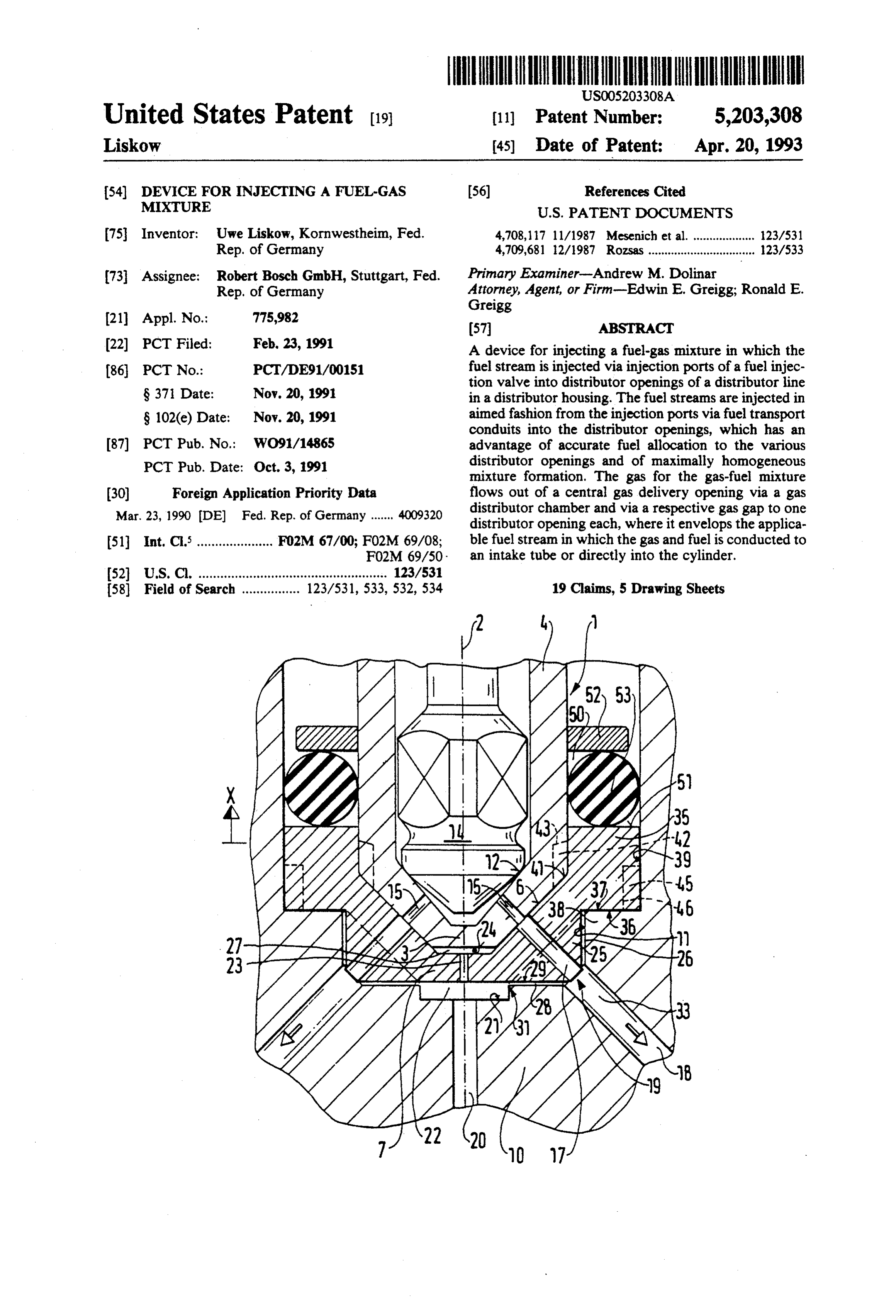
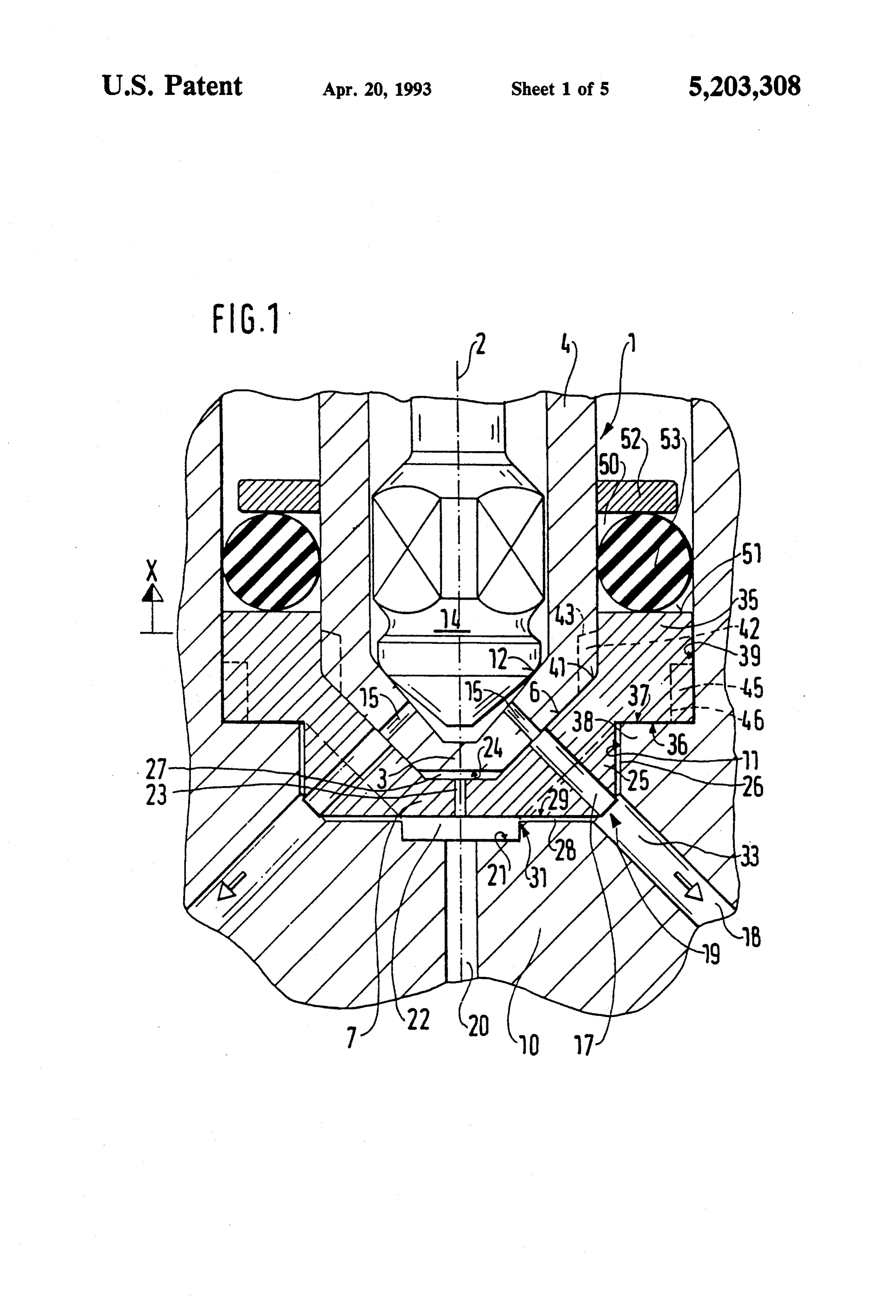
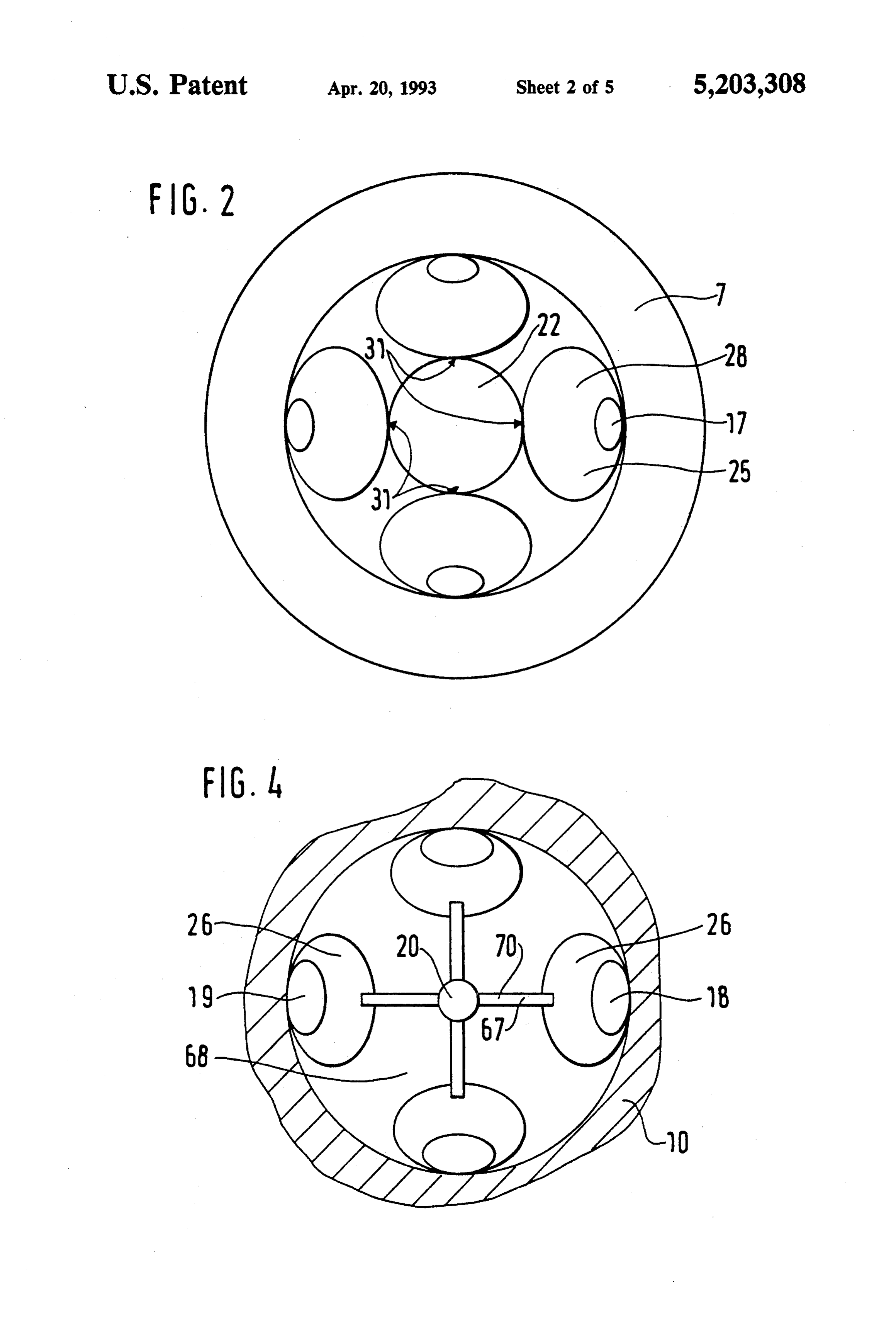
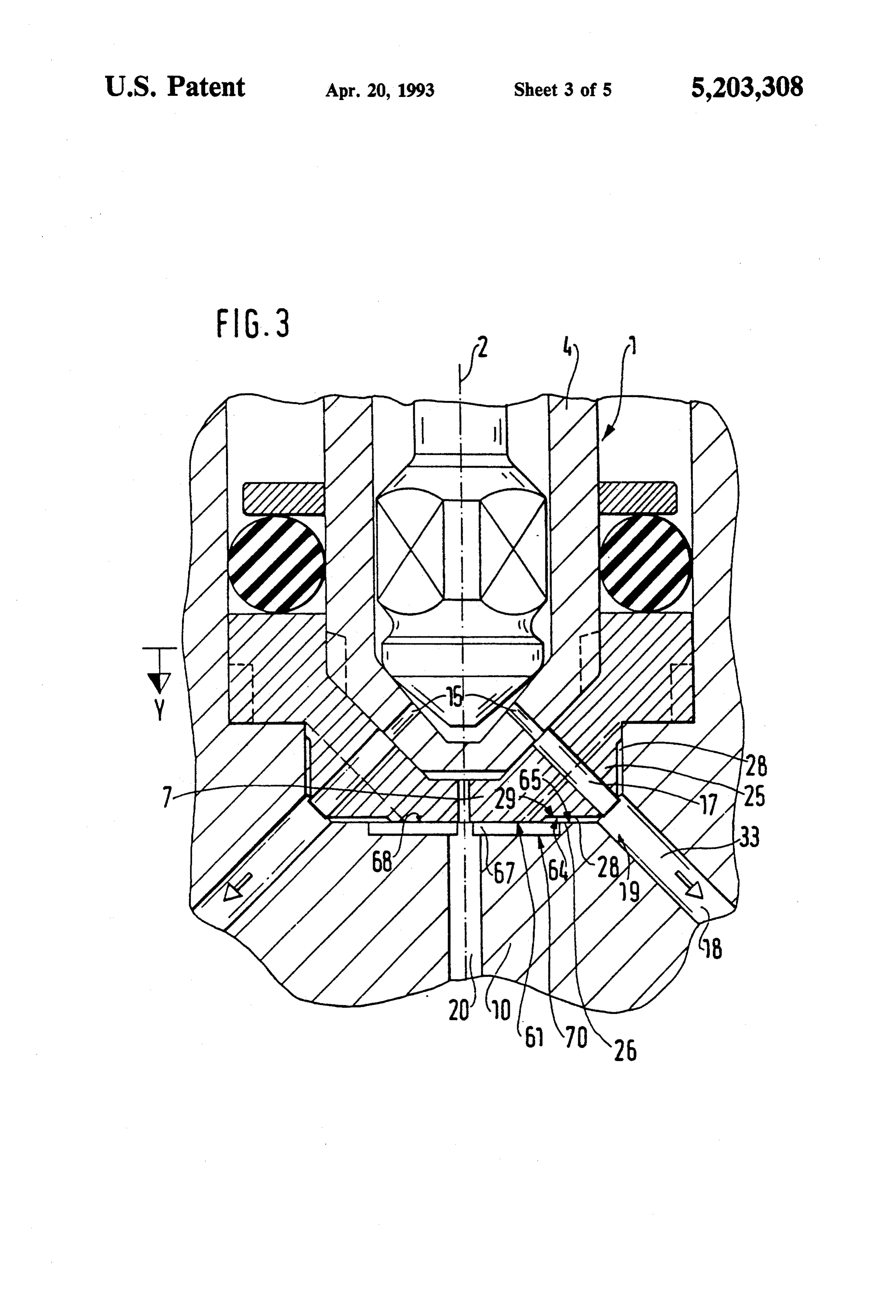
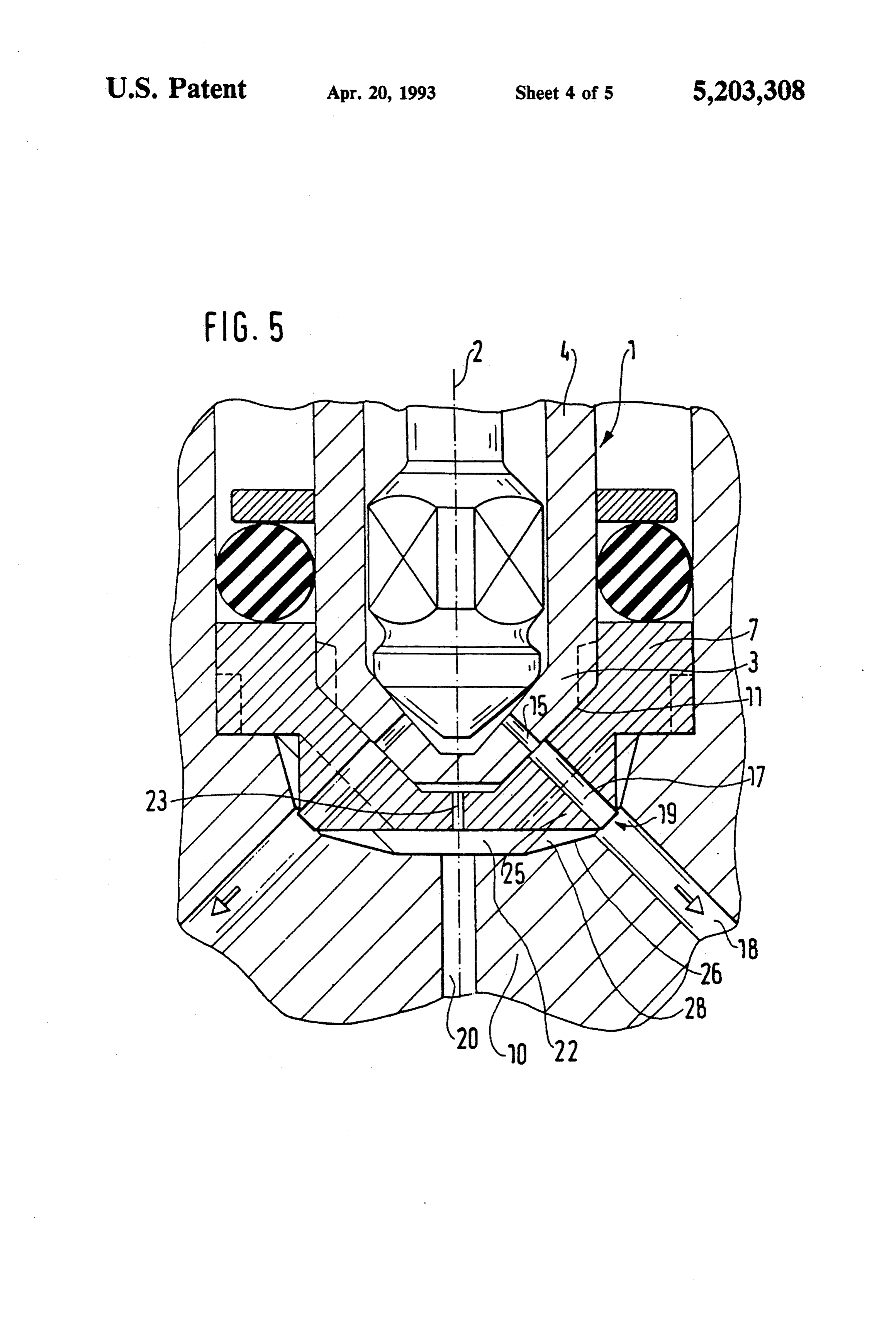
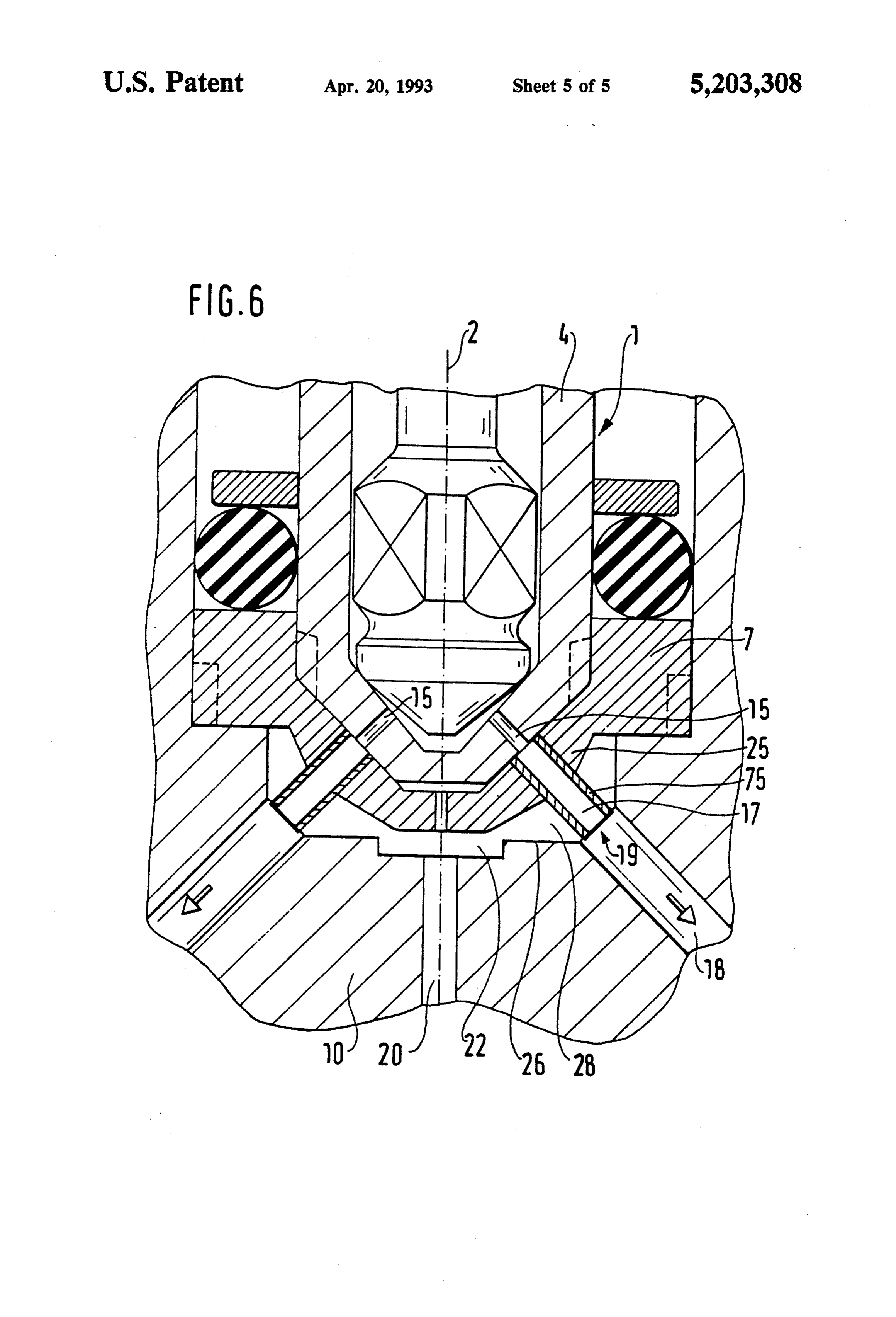
DRAWING 20 substantially smaller than the gas delivery opening 20 is Exemplary embodiments of the invention are shown embodied in the valve cap 7, also concentrically with in simplified form in the drawing and described in fur the longitudinal valve axis 2. The compensation bore 23 ther detail in the ensuing description. FIG. 1 shows a tion connects the gas distributor chamber 22 to a compensa chamber 27 embodied between an end face 24 of first exemplary embodiment, with a fuel injection valve 25 the injection shown in fragmentary form; FIG. 2 is a view of the valve cap 7. When end 3 of the fuel injection valve 1 and the valve cap in the direction of the arrow X of the first against the valve cap the fuel injection valve 1 is installed exemplary embodiment; FIG. 3 shows a second exem 7, it is thus attained that the air plary embodiment with a fuel injection valve shown in located between the fuel injection valve 1 and the valve cap 7 can escape through the compensation bore 23. If fragmentary form; FIG. 4 is a view of the distributor 30 leakage housing in the direction of the arrow Y of the second contact ofunexpectedly the fuel occurs between the fluid-tight injection valve 1 with the valve cap exemplary embodiment; FIG. 5 shows a third exem 7 during operation of the device plary embodiment; and FIG. 6 shows a fourth exem tion, then the mist of fuel passes according through to the inven the compensa plary embodiment. tion bore 23 into the gas distributor chamber 22 and DESCRIPTION OF THE EXEMPLARY 35 from there is entrained by the gas flow to the distributor
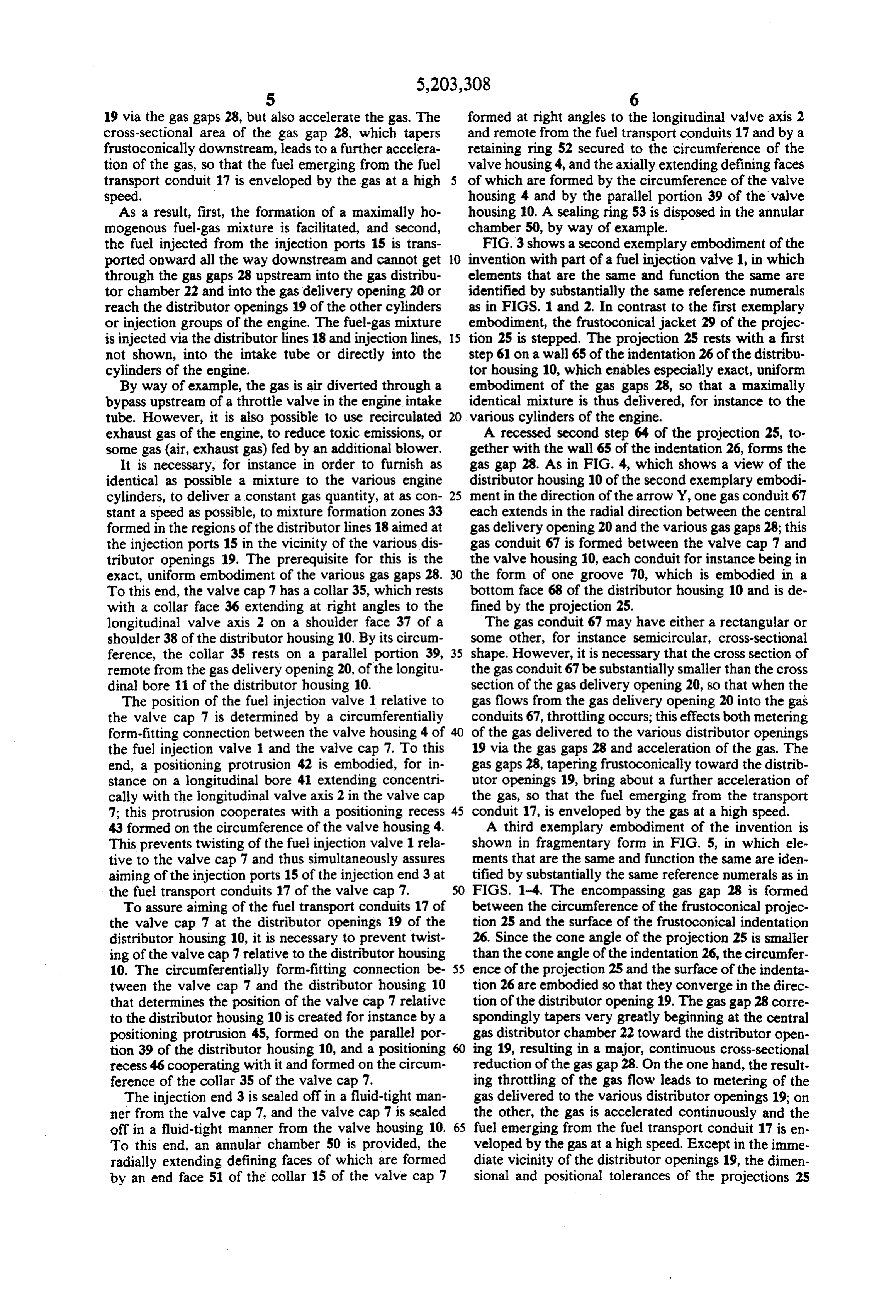
The device for injecting a fuel-gas mixture into an conical The valve cap 7 is provided with a number of frusto intake tube or directly into the cylinders of an internal distributor projections 25, corresponding to the number of combustion engine, shown by way of example in FIG. 1 tor openingopenings 19; the 19 and each aimed at one distribu fuel transport conduits 17 extend in longitudinal section and in fragmentary form, has a concentrically through these projections. With their fuel injection valve 1, which with its frustoconical in frustoconical jacket 29, the projections 25 protrude into jection end, embodied concentrically with a longitudi frustoconical indentations 26 of the distributor housing nal valve axis 2 of a valve housing 4, rests on a frusto 10, with a spacing between them such that a narrow, conical bearing face 6 of a valve cap 7, resulting in 45 encompassing simple yet very exact centering of the fuel injection ference of thegasprojectionsgap 28 is formed between the circum 25 and the surface of the valve relative to the valve cap 7. At least in the axial indentations 26, so that after emerging from the fuel direction, the valve cap 7 is disposed between the injec transport conduit 17, the fuel stream is fully enveloped tion end 3 of the fuel injection valve 1 and a distributor by a gas stream. Each gas gap 28 extends from the gas housing 10, which fits around a stepped longitudinal 50 distributor chamber 22 to a respective distributor open bore 11 of the injection end 3, the valve cap 7, and at ing 19, forming the bottom of an indentation 26. If the least part of the fuel injection valve 1. ratio between the narrowest area of the gas gap 28 and A fuel injection valve 1 has a valve closing body 14 the distributor opening 19 is overly low, the danger cooperating with a fixed valve seat 12 and actuatable as exists that the quantity of fuel injected by the injection a function of operating state. Downstream of the valve 55 ports 15 of the fuel injection valve will be affected by seat 12, the injection end 3 of the fuel injection valve 1 the feedback from the gas flow. The projections 25 with has a number of injection ports 15, for example four of the fuel transport conduits 17 may terminate immedi them, corresponding to the number of engine cylinders ately above, at the same height as, or, as shown in the or injection groups, each group including a plurality of drawing, inside the distributor openings 19. engine cylinders. A number of fuel transport conduits 60 FIG. 2 is a view of the valve cap 7 of the first exem 17, open on both ends, corresponding to the number of plary embodiment, shown in FIG. 1, in the direction of injection ports 15 and aimed at them, is embodied in the the arrow X. The cylindrical gas distributor chamber 22 valve cap 7; each of these conduits discharge into one communicates with the narrow gas gaps 28, which distributor opening 19 disposed in the distributor hous taper frustoconically toward the distributor openings ing 10 concentrically with the injection ports 15. Begin 65 19, each via a respective throttle restriction 31 formed ning at the distributor openings 19, distributor lines 18 at the transition; because of the major cross-sectional aimed at the fuel transport conduits 17 extend within the reduction, the throttle restrictions not only effect exact distributor housing 10. metering of the gas delivered to the distributor openings
Page 9
19 via the gas gaps 28, but also accelerate the gas. The formed at right angles to the longitudinal valve axis 2 cross-sectional area of the gas gap 28, which tapers and remote from the fuel transport conduits 17 and by a frustoconically downstream, leads to a further accelera retaining ring 52 secured to the circumference of the tion of the gas, so that the fuel emerging from the fuel valve housing 4, and the axially extending defining faces transport conduit 17 is enveloped by the gas at a high of which are formed by the circumference of the valve speed. housing 4 and by the parallel portion 39 of the valve As a result, first, the formation of a maximally ho housing 10. A sealing ring 53 is disposed in the annular mogenous fuel-gas mixture is facilitated, and second, chamber 50, by way of example.
the fuel injected from the injection ports 15 is trans FIG.3 shows a second exemplary embodiment of the ported onward all the way downstream and cannot get 10 invention with part of a fuel injection valve 1, in which through the gas gaps 28 upstream into the gas distribu elements that are the same and function the same are tor chamber 22 and into the gas delivery opening 20 or identified by substantially the same reference numerals reach the distributor openings 19 of the other cylinders as in FIGS. 1 and 2. In contrast to the first exemplary or injection groups of the engine. The fuel-gas mixture embodiment, the frustoconical jacket 29 of the projec is injected via the distributor lines 18 and injection lines, 15 tion 25 is stepped. The projection 25 rests with a first not shown, into the intake tube or directly into the step 61 on a wall 65 of the indentation 26 of the distribu cylinders of the engine. tor housing 10, which enables especially exact, uniform By way of example, the gas is air diverted through a embodiment of the gas gaps 28, so that a maximally bypass upstream of a throttle valve in the engine intake identical mixture is thus delivered, for instance to the tube. However, it is also possible to use recirculated 20 various cylinders of the engine.
exhaust gas of the engine, to reduce toxic emissions, or A recessed second step 64 of the projection 25, to some gas (air, exhaust gas) fed by an additional blower. gether with the wall 65 of the indentation 26, forms the It is necessary, for instance in order to furnish as gas gap 28. As in FIG. 4, which shows a view of the identical as possible a mixture to the various engine distributor housing 10 of the second exemplary embodi cylinders, to deliver a constant gas quantity, at as con 25 ment in the direction of the arrow Y, one gas conduit 67 stant a speed as possible, to mixture formation zones 33 each extends in the radial direction between the central formed in the regions of the distributor lines 18 aimed at gas delivery opening 20 and the various gas gaps 28; this the injection ports 15 in the vicinity of the various dis gas conduit 67 is formed between the valve cap 7 and tributor openings 19. The prerequisite for this is the the valve housing 10, each conduit for instance being in exact, uniform embodiment of the various gas gaps 28. 30 the form of one groove 70, which is embodied in a To this end, the valve cap 7 has a collar 35, which rests bottom face 68 of the distributor housing 10 and is de with a collar face 36 extending at right angles to the fined by the projection 25.
longitudinal valve axis 2 on a shoulder face 37 of a The gas conduit 67 may have either a rectangular or shoulder 38 of the distributor housing 10. By its circum some other, for instance semicircular, cross-sectional ference, the collar 35 rests on a parallel portion 39, 35 shape. However, it is necessary that the cross section of remote from the gas delivery opening 20, of the longitu the gas conduit 67 be substantially smaller than the cross dinal bore 11 of the distributor housing 10. section of the gas delivery opening 20, so that when the The position of the fuel injection valve 1 relative to gas flows from the gas delivery opening 20 into the gas the valve cap 7 is determined by a circumferentially conduits 67, throttling occurs; this effects both metering form-fitting connection between the valve housing 4 of 40 of the gas delivered to the various distributor openings the fuel injection valve 1 and the valve cap 7. To this 19 via the gas gaps 28 and acceleration of the gas. The end, a positioning protrusion 42 is embodied, for in gas gaps 28, tapering frustoconically toward the distrib stance on a longitudinal bore 41 extending concentri utor openings 19, bring about a further acceleration of cally with the longitudinal valve axis 2 in the valve cap the gas, so that the fuel emerging from the transport 7; this protrusion cooperates with a positioning recess 45 conduit 17, is enveloped by the gas at a high speed. 43 formed on the circumference of the valve housing 4. A third exemplary embodiment of the invention is This prevents twisting of the fuel injection valve 1 rela shown in fragmentary form in FIG. 5, in which ele tive to the valve cap 7 and thus simultaneously assures ments that are the same and function the same are iden aiming of the injection ports 15 of the injection end 3 at tified by substantially the same reference numerals as in the fuel transport conduits 17 of the valve cap 7. 50 FIGS. 1-4. The encompassing gas gap 28 is formed To assure aiming of the fuel transport conduits 17 of between the circumference of the frustoconical projec the valve cap 7 at the distributor openings 19 of the tion 25 and the surface of the frustoconical indentation distributor housing 10, it is necessary to prevent twist 26. Since the cone angle of the projection 25 is smaller ing of the valve cap 7 relative to the distributor housing than the cone angle of the indentation 26, the circumfer 10. The circumferentially form-fitting connection be 55 ence of the projection 25 and the surface of the indenta tween the valve cap 7 and the distributor housing 10 tion 26 are embodied so that they converge in the direc that determines the position of the valve cap 7 relative tion of the distributor opening 19. The gas gap 28 corre to the distributor housing 10 is created for instance by a spondingly tapers very greatly beginning at the central positioning protrusion 45, formed on the parallel por gas distributor chamber 22 toward the distributor open tion 39 of the distributor housing 10, and a positioning ing 19, resulting in a major, continuous cross-sectional recess 46 cooperating with it and formed on the circum reduction of the gas gap 28. On the one hand, the result ference of the collar 35 of the valve cap 7. ing throttling of the gas flow leads to metering of the The injection end 3 is sealed offin a fluid-tight man gas delivered to the various distributor openings 19; on ner from the valve cap 7, and the valve cap 7 is sealed the other, the gas is accelerated continuously and the off in a fluid-tight manner from the valve housing 10. 65 fuel emerging from the fuel transport conduit 17 is en To this end, an annular chamber 50 is provided, the veloped by the gas at a high speed. Except in the imme radially extending defining faces of which are formed diate vicinity of the distributor openings 19, the dimen by an end face 51 of the collar 15 of the valve cap 7 sional and positional tolerances of the projections 25
Page 10
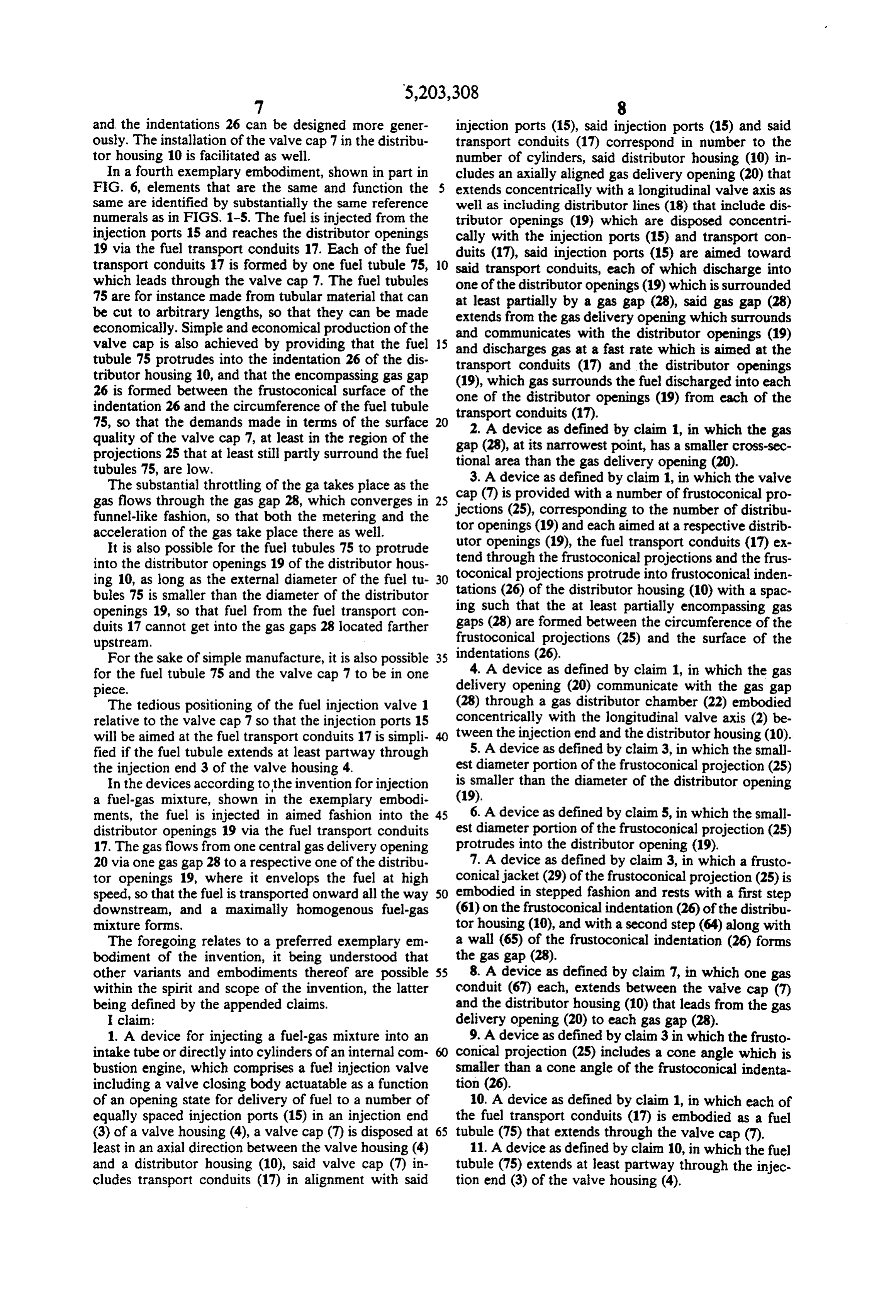
and the indentations 26 can be designed more gener injection ports (15), said injection ports (15) and said ously. The installation of the valve cap 7 in the distribu transport conduits (17) correspond in number to the tor housing 10 is facilitated as well. number of cylinders, said distributor housing (10) in In a fourth exemplary embodiment, shown in part in cludes an axially aligned gas delivery opening (20) that FIG. 6, elements that are the same and function the extends concentrically with a longitudinal valve axis as same are identified by substantially the same reference well as including distributor lines (18) that include dis numerals as in FIGS. 1-5. The fuel is injected from the tributor openings (19) which are disposed concentri injection ports 15 and reaches the distributor openings cally with the injection ports (15) and transport con 19 via the fuel transport conduits 17. Each of the fuel duits (17), said injection ports (15) are aimed toward transport conduits 17 is formed by one fuel tubule 75, O said transport conduits, each of which discharge into which leads through the valve cap 7. The fuel tubules one of the distributor openings (19) which is surrounded 75 are for instance made from tubular material that can at least partially by a gas gap (28), said gas gap (28) be cut to arbitrary lengths, so that they can be made extends from the gas delivery opening which surrounds economically. Simple and economical production of the and communicates with the distributor openings (19) valve cap is also achieved by providing that the fuel 15 and discharges gas at a fast rate which is aimed at the tubule 75 protrudes into the indentation 26 of the dis tributor housing 10, and that the encompassing gas gap transport
conduits (17) and the distributor openings gas surrounds the fuel discharged into each 26 is formed between the frustoconical surface of the one of the distributor openings (19) from each of the indentation 26 and the circumference of the fuel tubule 75, so that the demands made in terms of the surface 20 transport conduits (17).
2. A device as defined by claim 1, in which the gas quality of the valve cap 7, at least in the region of the gap (28), at its narrowest point, has a smaller cross-sec projections 25 that at least still partly surround the fueltional area than the gas delivery opening (20). tubules 75, are low.
The substantial throttling of the ga takes place as the cap3. (7)
A device as defined by claim 1, in which the valve is provided with a number of frustoconical pro gas flows through the gas gap 28, which converges in 25 jections (25), corresponding to the number of distribu funnel-like fashion, so that both the metering and the tor openings (19) and each aimed at a respective distrib acceleration of the gas take place there as well. utor openings (19), the fuel transport conduits (17) ex It is also possible for the fuel tubules 75 to protrude into the distributor openings 19 of the distributor hous tend through the frustoconical projections and the frus ing 10, as long as the external diameter of the fuel tu 30 toconical projections protrude into frustoconical inden bules 75 is smaller than the diameter of the distributor tations (26) of the distributor housing (10) with a spac openings 19, so that fuel from the fuel transport con ing such that the at least partially encompassing gas duits 17 cannot get into the gas gaps 28 located farther gaps (28) are formed between the circumference of the upstream. frustoconical projections (25) and the surface of the For the sake of simple manufacture, it is also possible 35 indentations (26).
for the fuel tubule 75 and the valve cap 7 to be in one 4. A device as defined by claim 1, in which the gas p1ece. delivery opening (20) communicate with the gas gap The tedious positioning of the fuel injection valve 1 (28) through a gas distributor chamber (22) embodied relative to the valve cap 7 so that the injection ports 15 concentrically with the longitudinal valve axis (2) be will be aimed at the fuel transport conduits 17 is simpli tween the injection end and the distributor housing (10). fied if the fuel tubule extends at least partway through 5. A device as defined by claim 3, in which the small the injection end 3 of the valve housing 4. est diameter portion of the frustoconical projection (25) In the devices according to the invention for injection is smaller than the diameter of the distributor opening a fuel-gas mixture, shown in the exemplary embodi (19).
ments, the fuel is injected in aimed fashion into the 45 6. A device as defined by claim 5, in which the small distributor openings 19 via the fuel transport conduits est diameter portion of the frustoconical projection (25) 17. The gas flows from one central gas delivery opening protrudes into the distributor opening (19). 20 via one gas gap 28 to a respective one of the distribu 7. A device as defined by claim 3, in which a frusto tor openings 19, where it envelops the fuel at high conical jacket (29) of the frustoconical projection (25) is speed, so that the fuel is transported onward all the way 50 embodied in stepped fashion and rests with a first step downstream, and a maxinally homogenous fuel-gas (61) on the frustoconical indentation (26) of the distribu mixture forms. tor housing (10), and with a second step (64) along with The foregoing relates to a preferred exemplary em a wall (65) of the frustoconical indentation (26) forms bodiment of the invention, it being understood that the gas gap (28).
other variants and embodiments thereof are possible 55 8. A device as defined by claim 7, in which one gas within the spirit and scope of the invention, the latter conduit (67) each, extends between the valve cap (7) being defined by the appended claims. and the distributor housing (10) that leads from the gas I claim: delivery opening (20) to each gas gap (28). 1. A device for injecting a fuel-gas mixture into an 9. A device as defined by claim 3 in which the frusto intake tube or directly into cylinders of an internal com conical projection (25) includes a cone angle which is bustion engine, which comprises a fuel injection valve Smaller than a cone angle of the frustoconical indenta including a valve closing body actuatable as a function tion (26).
of an opening state for delivery of fuel to a number of 10. A device as defined by claim 1, in which each of equally spaced injection ports (15) in an injection end the fuel transport conduits (17) is embodied as a fuel (3) of a valve housing (4), a valve cap (7) is disposed at 65 tubule (75) that extends through the valve cap (7). least in an axial direction between the valve housing (4) 11. A device as defined by claim 10, in which the fuel and a distributor housing (10), said valve cap (7) in tubule (75) extends at least partway through the injec cludes transport conduits (17) in alignment with said tion end (3) of the valve housing (4).
Page 11
12. A device as defined by claim 10, in which the fuel and rests on a frustoconical bearing face (6) of the valve tubule (75) protrudes into the frustoconical indentation cap (7).
(26) of the distributor housing (10), and that the at least 17. A device as defined by claim 1, in which the valve partially encompassing gas gap (28) is formed between cap (7) rests with a collar (35) on a shoulder (38) of the the surface of the frustoconical indentation (26) and the distributor housing (4).
circumference of the fuel tubule (75). 18. A device as defined by claim 1, in which the 13. A device as defined by claim 10, in which the position of the valve cap (7) with respect to the valve outer diameter of the fuel tubule (75) is smaller than the housing (4) is determined by a circumferentially form diameter of the distributor opening (19). fitting connection between the valve cap (7) and the 14. A devices defined by claim 3, in which the fuel O valve housing (4).
tubule (75) protrudes into the distributor opening (19). 19. A device as defined by claim 1, in which the 15. A device as defined by one of claim 10 in which position of the valve cap (7) with respect to the distribu the fuel tubules (75) and the valve cap (7) are embodied tor housing (10) is determined by a circumferentially in one piece. form-fitting connection between the valve cap (7) and 16. A device as defined by claim 1, in which the 5 the distributor housing (10).
injection end (3) of the valve housing (4) is frustoconical X
Provenance
- Collection
- Cited prior art
- Original PDF
- patentimages.storage.googleapis.com →
- Filed
- 1991-02-23
- Pages
- 11
- Method
- pdftotext (the PDF's own text layer) + pdftoppm 300dpi page scans
- Source
- Google Patents bibliographic record
- Granted
- 1993-04-20
- Inventors
- Uwe Liskow; Robert Bosch GmbH
- Transcribed from
- patentimages.storage.googleapis.com →