patent · US6226981
Air to fuel ratio control for gas engine and method of operation
8 May 2001
Page 1 — bibliographic record
(12) United States Patent (10) Patent No.: US 6,226,981 B1 Bruch et al. (45) Date of Patent: May 8, 2001
(54) AIR TO FUEL RATIO CONTROL FOR GAS 4,953,351 9/1990 Motz et al. . ENGINE AND METHOD OF OPERATION 5,138,163 8/1992 Butler et al. ......................... 250/339 5,138,835 8/1992 Bender et al. ......................... 60/278 (75) Inventors: Kevin L. Bruch, West Lafayette, IN 55:
amburg et al. .
S. teter senschwander, scholzmatt (CH)
Gras et al..
5,837.903 * 11/1998 Weigand ........................... 73/861.42 (73) Assignee: Caterpillar Inc., Peoria, IL (US) 6,012,284 1/2000 Tanaka et al. ......................... 60/297 (*) Notice: Subject to any disclaimer, the term of this OTHER PUBLICATIONS patent is extended or adjusted under 35 &&Y - ss U.S.C. 154(b) by 0 days. Design and Develop. of the Caterpillar 3600...", by R.D. Nevinger, presented at the Energy-Sources Tech. Conf.,
(21) Appl. No.: 09/243,055 “Operation of a Caterpillar 3516 . . . , N.C. Macari et al., (22) Filed: Feb. 2, 1999 Journal of Engineer. for Gas Turbines and Power, Oct. 1987, 7 vol. 109, pp. 443–447.
(51) Int. Cl." ........................................................ FO1N 3700 Caterpillar G35OO High Efficiency Engine Development, by (52) U.S. CI. metsi 95. K.L. Bruch presented at ASME Conference, Fall 1995, Milwaukee, WI.
(58) Field of Search .............................. 60/274, 276, 285, 60/280, 278, 297; 123/32 EA, 478; 73/861.42; * cited by examiner
Primary Examiner Thomas Denion (56) References Cited ASSistant Examiner Thai-Ba Trieu (74) Attorney, Agent, or Firm-Gordon H. Telfer
3,973.529 8/1976 Wessel et al. . (57) 4,141,326 2/1979 Wober. A fuel System for a gas engines has exhaust gas monitors for 4,178,884 12/1979 Norimatsu et al.. signals (p, T, V) related to exhaust gas mass flow with an air 4,319,451 3/1982 Tajima et al.. to fuel controller that acts to adjust the intake of a gaseous 26. : 3.E. Mill aWalCOto etC alal. .................. 123/478 fuel, which can vary widely in composition, to maintain a 4,801805 - 1/1989 Butler et al... 3, desired level of exhaust gas mass flow. 4,835,963 6/1989 Hardy ..................................... 60/274 4,867,127 9/1989 Quirchmayr et al.. 18 Claims, 1 Drawing Sheet
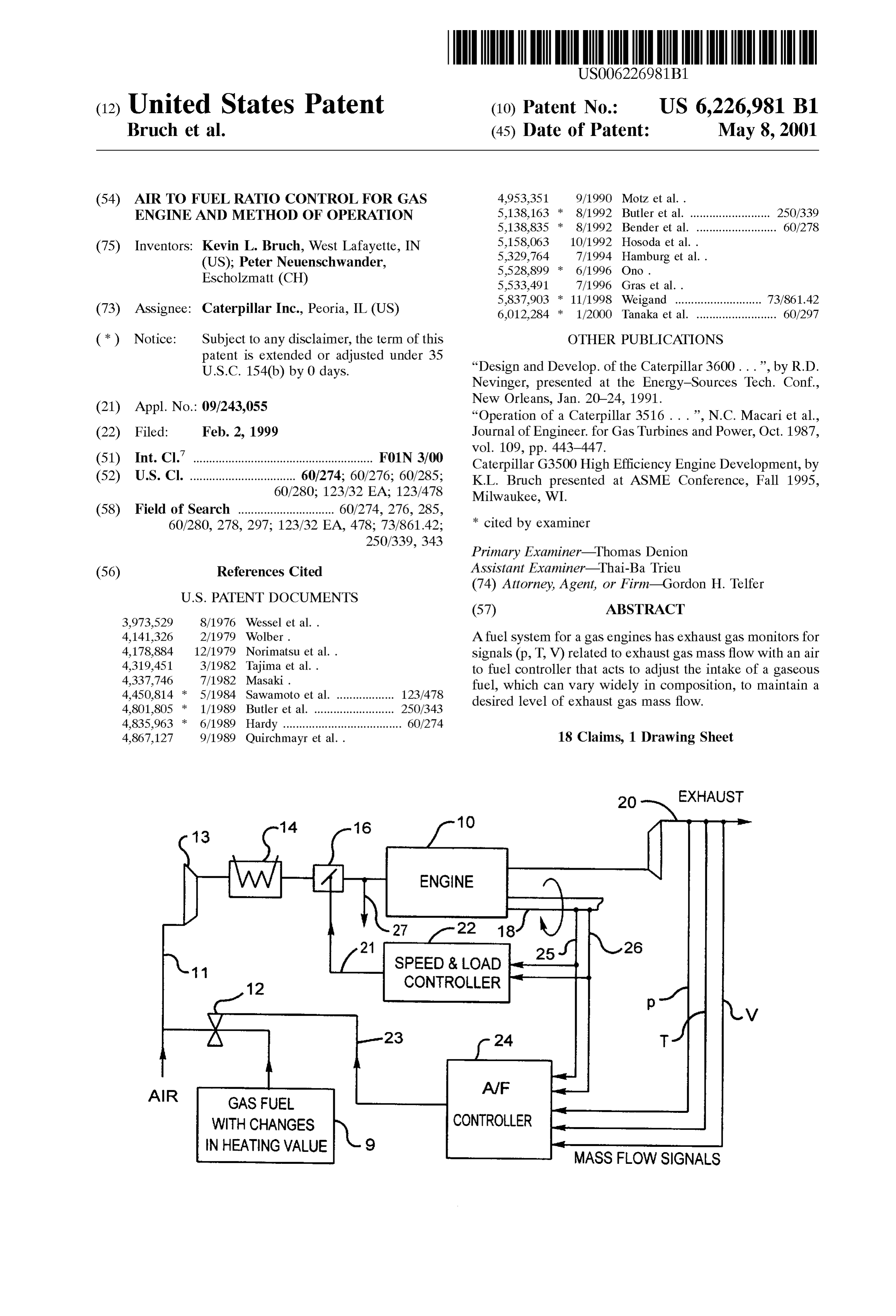
ENGINE
SPEED & LOAD
WITH CHANGES CONTROLLER
NHEATING VALUE
MASS FLOW SIGNALS
Page 2
Drawing sheet — no readable text.
Page 3
AIR TO FUELRATO CONTROL FOR GAS For example, in Some prior engine fuel Systems, an ENGINE AND METHOD OF OPERATION oxygen (O2) sensor was used in the exhaust to provide readings for accurate adjustment of the A/F ratio. Use of
TECHNICAL FIELD Such O2 Sensors can provide Safe operation of a gas fueled, This invention relates to internal combustion engines and lean burn engine with low NOx emission. However, if an O2 fuel Systems therefore, and particularly to an arrangement of Sensor failure occurs, an engine may have to be shut down. apparatus and a method for control of the air to fuel ratio (0. But now, with the present invention, highly reliable Sensors or A/F) in engines fueled with a gaseous fuel Subject to can be used to control the A/F ratio according to exhaust gas variation in composition. flow, either by itself or in conjunction with, or as a back up to, control with an O2 Sensor (or other sensor of exhaust
BACKGROUND OF THE INVENTION composition).
"Gas' engines in the context of the present description are Molecular weight differences of various fuels cause those designed for operation with a fuel that is gaseous under Smaller differences in the exhaust than in the intake fuel normal ambient conditions. The fuel can be any of various 15 mixture which is an advantage for more precise control. hydrocarbon gases, carbon monoxide, hydrogen, and mix The invention can be especially Suited for use when it is tures of two or more gases. Such engines are frequently used considered desirable to have air to fuel controlled according in Stationary applications and use fuel Supplies where the to the exhaust mass flow. The exhaust mass flow is in direct composition of the fuel can vary considerably, including relation to emissions, at a given load and Speed. The present landfills and pipelines. Typical engine ratings can be, for technique is a highly accurate NOX control technique but example, 50 HP to 5000 HP. The air to fuel ratio of an engine without a need for having a NOx sensor (or other gas running on a gas fuel is adjusted to load and Speed. Where composition analyzer) in the exhaust, which would incur the fuel has a varying composition, its composition and Substantially greater cost.
molecular weight are usually not known. Variation in the These and other aspects of the inventive apparatus and fuel composition may result in undesirably high NOx emis 25 method will become more apparent from the following SOS. description.
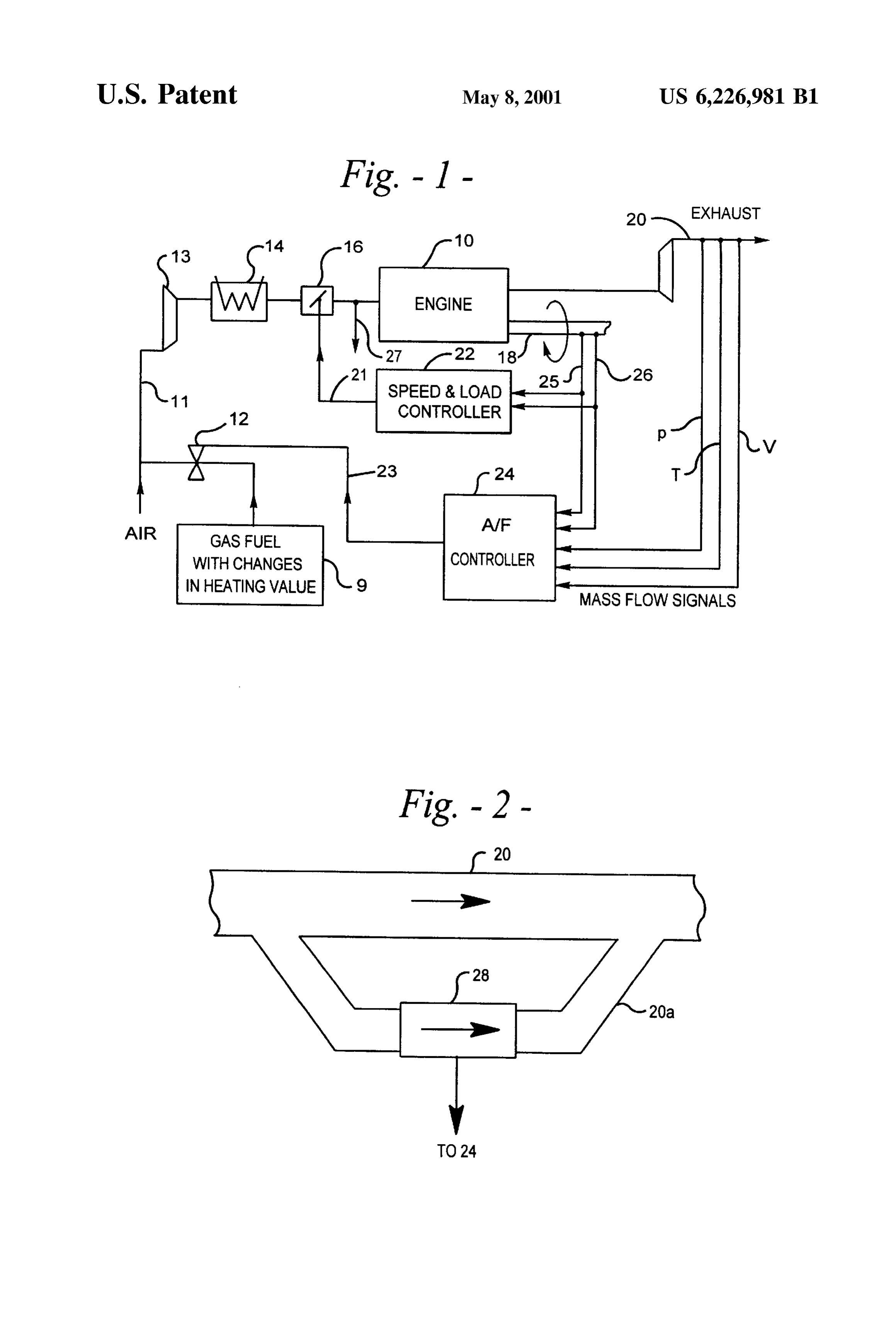
based on the idea of adjusting the air to fuel ratio 2 (lamda) BRIEF DESCRIPTION OF THE DRAWINGS based on reading the air and fuel mixture pressure upstream FIG. 1 is a Schematic block diagram of an engine and fuel of the inlet valves to the engine. For example, if a constant System in accordance with an example of the present inven engine output is required, an increase in that pressure can be tion; and caused by an increase in 2 (or a leaning of the mixture). In FIG. 2 is a Schematic diagram of a portion of a System Such a System, all the relevant input signals for the control Such as that of FIG. 1.
of ) are Sensed on the input Side of the engine.
SUMMARY OF THE INVENTION 35 DESCRIPTION OF THE PREFERRED
EMBODIMENTS
In accordance with the invention, a fuel System for a gas engine includes an air to fuel ratio controller Supplied with Before getting into more specific description of embodi input Signals from the exhaust So the controller can cause an ments of the invention, Some general description of the adjustment in the air to fuel ratio according to the mass flow 40 principle of using exhaust mass flow for controlling the A/F of exhaust gases. The adjustment can be made by operation ratio will be given. Experience shows that a constant intake of a valve at the fuel inlet before mixing with air. For manifold pressure correlates to a constant level of NOx example, the controller may receive a signal representing emission for a certain load and Speed, even if the heating mass flow from a hot wire anemometer in the exhaust or a value of the fuel changes. This can be explained as follows: plurality of Signals can be Supplied to the controller includ 45 NOx formation is determined mainly by temperature, ing exhaust gas preSSure, and exhaust gas temperature. preSSure and residence time. For a certain Speed and timing Volumetric flow of exhaust gas can be measured by a pitot the residence time is virtually constant. To get the obtained tube. The controller can determine mass flow from the torque, a certain pressure has to be achieved. Therefore only Volumetric flow and/or from the measured exhaust gas the temperature can vary and influence the NOx formation. preSSure and temperature. Preferably, there is a Signal also 50 The variable which influences the temperature is the amount for the temperature of the inlet mixture of air and fuel so the of a gas or the number of molecules in the cylinder. With controller can take variations in Such temperature into more molecules, a lower temperature is necessary for the acCOunt. Same pressure and Vice versa. This means that we want to In practice of the invention, the described A/F control may control the molecular flow of the fuel and air mixture to the be one loop (e.g., the outer loop) of a two loop control 55 cylinder, besides the charge temperature at the beginning of circuit. The other (inner) loop would normally be for load the compression. If the heating value of the fuel increases, and Speed control affecting actuatorS Such as a throttle valve a Smaller amount of fuel is necessary to get the same power. or a waste gate. Two loop control Systems have been The lack of molecules because of the reduced fuel mass flow previously used but not with the A/F ratio control based on is roughly compensated by an increased air flow. exhaust gas mass flow, particularly for running on fuels of 60 The intake manifold preSSure is related to the molecular varying composition. flow of the mixture. This explains the experimental experi A variety of different sensors may be employed but it is ence of intake manifold pressure as a main indicator of NOX not necessary to monitor the chemical composition of the formation. If the molecular weight M of the mixture gas is exhaust gases directly. The apparatus and method of the changing due to a changing heating value of the fuel, the invention may be used alone or, if desired, in concert with 65 molecular flow n and the mass flow m respectively are other methods of NOX estimation or air to fuel control or as changing as follows (speed, load, intake manifold pressure a reasonableneSS check or back up method. and temperature constant):
Page 4
these extreme examples (except hydrogen 7.6%). If the it. -- and in ~ WM exhaust gas flow is measured rather than mixture gas flow, VM deviations are Smaller than 1.1% (except of carbon monox ide with 4.7% and hydrogen with 2.9%).
The foregoing analysis Supports the idea that mass flow
If the differential pressure of the mixture gas or exhaust gas measuring is a good way to keep the combustion tempera flow are measured with a Pitot static tube, the same rela ture constant and mass flow measuring of exhaust gases tionships are valid. provides an opportunity for precise measurements. To check the influence of changing fuel, 100% methane In this discussion the impact of changing heat capacity of and 100% propane were compared. To keep the energy the charge because of changing composition of fuel, A/F (number of BTU) in the cylinder constant, the amount of ratio and humidity is ignored as being of Secondary impor methane molecules required is 2.6 times the amount of tance.
propane molecules. To keep the total amount of molecules
With constant Speed, load and timing we want to take the constant, a specific air to fuel ratio (0) stays for methane and propane nearly the Same. The molecular weight of) =2 air to heating value of the fuel and the initial temperature of the methane mixture is 27.9 kg/kmol and for a 2-2.14 air to 15 charge as independent variables into consideration to reach propane mixture it is 28.9 kg/kmol. The change in molecular the temperature goal.
weight changes the mass or molecular flow only by 1.8% for FIG. 1 shows a general Schematic of an example of an this extreme example, if intake manifold preSSure and tem engine and fuel System in accordance with the invention. perature are held constant (Pitot static tube: constant differ Gas fueled engine 10 is Supplied a mixture of air (A) and fuel ential pressure, absolute gas pressure and gas temperature). (F), through a usual arrangement including a mixture con The molecular weight of the exhaust gas is 28.3 kg/kmol for duit 11 and a fuel flow valve 12, a compressor 13, a cooler methane fuel and 28.7 kg/kmol for propane fuel. For the 14 and a throttle valve 16. The fuel, from a supply 9, may same arrangement the A/F ratios (mass) are also similar for be a gaseous fuel Such as one previously described that is not both fuels. reliably of a fixed composition, Such as one that varies For a fuel with 50% methane and 50% carbon dioxide the 25 appreciably in its heating value or relative detonation ten air fuel mixture will have a molecular weight of 28.8 dency. The engine 10 can itself be a conventional gas fuel kg/kmol and exhaust gas will have a molecular weight of engine in accordance with prior practice. From combustion 29.1 kg/kmol. The specific air to fuel ratio will be 1.9. The of the fuel in the engine 10, mechanical power is developed A/F ratios (mass) will decrease to a fourth of the value of the on a shaft 18 and exhaust gases pass out through an exhaust methane or propane fuel. conduit 20.
The mass flow of the mixture gas and the exhaust gas are Two control loops are included in FIG. 1. A first loop 21 equal. The molecular flows are not. The more the weight of includes a Speed and load controller 22 that gets Speed and the fuel molecules differ from air and the richer the mixture, load signals 25 and 26 from the engine output shaft 18. A the larger the difference in the molecular flow. Because the second loop 23 has an A/F controller 24 to reach the number of molecules change during combustion, it is not 35 molecular flow goal or mass flow goal. The Speed-load loop obvious whether the mixture molecular flow or the exhaust 21 has the throttle valve 16, an exhaust bypass (not shown) molecular flow matches the lean condition in the cylinder or a variable geometry turbocharger, as actuator. The flow better. At least for the above examples differences in loop 23 has the fuel flow valve 12 as actuator. The nominal molecular weight of mixture gas and exhaust gas can be value of the flow is stored in the controller 22 as a function neglected. 40 of speed and load 25 and 26. In addition the stored value is Other hydrocarbon gases, including ethane, ethylene, corrected depending upon the initial temperature of the propane, propylene, isobutanes, norbutane, isopentane, charge. This initial temperature depends on intake manifold norpentane, neopentane, hexane, heptane, octane, and temperature, on jacket water temperature, on the residual nonane are Suitable for gas fueled engines, as well as carbon mass and on the temperature of the residual mass. Line 27 monoxide and hydrogen, and mixtures (or blends) of the 45 represents a Signal line for the temperature of the fuel various gases. In applications of particular interest, the mixture entering the engine 10, Signals on line 27 may be composition of the fuel varies frequently and by a significant supplied to the controllers 22 and/or 24. The residual mass mangitude. For example, the heating value can vary by a is basically very Small for gas engines and it will be nearly wide margin, such as 120 BTU/ft3 for H2 to 2365 BTU/ft3 constant for a certain speed, load and exhaust flow (the for propane. The compositions encountered can also be 50 exhaust flow is controlled by the second control loop). Only contrasted by a methane number representing the relative the combination of very low load and low speed can increase detonation tendency of the fuel to that of methane. Engines the residual mass Significantly. Because of this, it is not of interest run on fuels with methane numbers ranging from necessary to take the residual mass and its temperature into 20-150. The present invention is particularly advantageous consideration for the usual engine envelope. But the intake in engine fuel Systems with a fuel Supply Susceptible to Such 55 manifold and jacket water temperatures are monitored to variations or even variations of a factor of two, or lesser but adjust the flow map.
Still appreciable variations, in Such qualities as the heating If pressure measurement is used for flow determination, value or the relative detonation tendency. compensation of temperature impact can be made based on Of the various gases and mixtures of gases, along with the ideal gas law with the exhaust gas temperature as follows methane and propane, differences in molecular weight of the 60 (mixture temperature if the mixture flow is measured): gas are Smaller than 5% compared to methane as a reference C=CTIT, (except hydrogen which is about 15% less than methane).
For exhaust gas changes Smaller than 2% (except for carbon This model approach takes the change in gas density monoxide with a 10% difference and hydrogen at -6%), if related to the Velocity or pressure measurement into con the air to fuel ratio is controlled by measuring e.g. intake 65 sideration. It does not compensate the higher amount of manifold pressure or mixture gas flow with a Pitot Static internal energy which is brought in the cylinder with a hotter tube, the systematic error in flow is smaller than 2.5% for all mixture gas due to higher intake manifold temperature or
Page 5
S 6 higher jacket water temperature. This effect can be compen respond to predetermined conditions among the monitored Sated with more detailed modeling or mapping. parameters to exercise a predetermined control function. In the example of FIG. 1, the A/F controller 24 is supplied Industrial Applicability
Signals about the exhaust gases from the exhaust conduit 20, The system and method of operation described allow wide for example a Signalp representing the exhaust gas pressure, variations in fuel composition without appreciable affect on a signal T representing the exhaust gas temperature, and a NOx emissions. Further, the invention can be implemented Signal V representing the exhaust gas Volumetric flow. Not using existing Sensor and controller technology but applied necessarily all three Signals p, T and V need be Supplied to to the particular conditions of gas engines. Therefore, gas controller 24, Signal V can be Sufficient or else signals p and engines may be located in more places, including locations T. where emissions are particularly important, and operate on Determination of conditions of the exhaust, for control of a wide range of fuels.
mass flow, is at least as effective in principle as determining It will be apparent that numerous variations can be made conditions of the intake fuel mixture and has the advantage from the Specific examples described above in keeping with of smaller differences in molecular weight for different fuels the Spirit and Scope of the invention. (except for CO) compared to intake fuel mixtures. 15 What is claimed is:
It is recognized that Sensors for monitoring the exhaust 1. A fuel System of an internal combustion engine having gases should be Sturdy to Stand up to the exhaust gas an intake for an air and fuel mixture and having an exhaust temperatures and corrosive or particulate composition. for gaseous products from the engine, comprising: Volumetric flow or Speed respectively can be measured a mechanism to vary the air to fuel ratio of the mixture; with a diaphragm, Venturi nozzle, Pitot static tube (Prandtl and tube), hot wire anonometer, etc. To reduce costs, existing an air to fuel ratio controller with one or more input mass flow measurement devices from the automotive indus Signals from the exhaust of the engine that vary in try are a good choice for use in engine Systems. Because cars accordance with a variation in mass flow of exhaust have much Smaller engines than industrial gas engines, the gases, Said controller being arranged to process Said whole mass flow cannot be measured with Such Sensors. 25 input signals and to produce an output adjustment This difficulty can be solved with an arrangement of a Signal applied to Said mechanism to adjust the air to bypass tube and calibration of the System. Automotive fuel ratio at the engine intake as a function of the engines generally do not run on any gaseous fuel and when Variation in mass flow of exhaust gases without any they do (liquefied natural gas, for example) the fuel has a input Signal from an exhaust gas oxygen Sensor. reliably consistent composition. However, Some Sensor tech 2. The system of claim 1 wherein: nology developed in the automotive field for various pur the air to fuel ratio controller receives among Said input poses not having to do with either the present invention or Signals a first signal representing exhaust gas pressure gas fuels of varying composition may be usefully applied and a Second Signal representing exhaust gas tempera here. If cheap automotive Sensors show a lack of reliability ture.
under gas engine operation conditions, multiple Sensors can 35 3. The system of claim 1 wherein: be used for redundancy. the air to fuel ratio controller receives among Said input FIG. 2 illustrates a portion of the exhaust conduit 20. Signals a signal representing Volumetric flow of exhaust Since the engine may be quite large, e.g., up to about 5000 gaS.
HP, exhaust flows are also quite large. Here, a part of conduit 4. The system of claim 1 wherein: 20 has a bypass, or a parallel loop, 20a with a smaller 40 the air to fuel ratio controller receives additional input croSS-Section than conduit 20. A flow measurement device Signals including an air and fuel intake temperature 28, Such as one of the types mentioned above, is disposed in Signal and engine Speed and load Signals. the bypass 20a So it can be selected from those that are 5. The system of claim 3 wherein: Suitably reliable but intended to operate over a range of the engine exhaust comprises a primary conduit of volumes less than that encountered in the conduit 20. 45
In the exhaust Stream more indirect measurements for exhaust gas and a bypass conduit of exhaust gas, having determining mass flow are Suitable also in Some applica Smaller cross-section, in parallel with a portion of the tions: primary conduit; and
Exhaust manifold pressure a flow measurement device for generating Said Signal Turbo-charger Speed combined with load and Speed of the 50 representing Volumetric flow is located in the bypass engine conduit.
Exhaust preSSure before and after a turbo charger com 6. The system of claim 1 where:
bined with load and Speed of the engine. the controller input Signals from the exhaust include a All these indirect methods on the exhaust side depend on Signal from apparatus Selected from the group consist the Single engine-turbo charger, inter-cooler, exhaust Stack 55 ing of a diaphragm, a Venturi nozzle, a Pitot Static tube, configuration. Over time, operating conditions are affected a Prandtl tube, and a hot wire anemometer. by reduced performance of the turbo charger because of 7. The system of claim 1 where:
abrasion and fouling of the turbine and compressor wheels the controller input Signals from the exhaust include a or because of increased friction of the bearings. Signal representing mass flow from a hot wire anemom Additionally, fouling of the air filter and inter cooler or 60 eter.
increased back pressure of the exhaust pipe change operat 8. A method of operating a fuel System of an engine ing conditions also. These indirect measurement techniques comprising the Steps of:
are normally, therefore, leSS preferred than the direct mea feeding an air and fuel mixture to the engine intake with Surements discussed in connection with FIG. 1. an adjustable mechanism to adjust the air to fuel ratio The controllers 22 and 24 may be basically in accordance 65 of the mixture;
with existing State of the art engine controllers, particularly reading one or more Signals from the engine exhaust electronic control modules that are set or programmed to relating to mass flow of the engine exhaust gases
Page 6
without reading any input Signal from an exhaust gas an intake air and fuel temperature Sensor Sensing the OXygen Sensor, temperature of the air and fuel mixture to the engine; comparing exhaust gas mass flow Signals to a predeter and, mined range of values, and an air to fuel ratio controller Supplied with the Signals adjusting air to fuel ratio to bring the exhaust gas maSS from the exhaust Sensors and the intake air and fuel flow to within Said predetermined range of values. temperature Sensor and producing an output air to fuel 9. The method of claim 8 wherein: ratio adjustment Signal to the mechanism to vary the air to fuel ratio.
the comparing Step is performed with allowance for 14. The system of claim 13 where: variation in the temperature of the air and fuel mixture.
10. The method of claim 8 wherein: the fuel Source Supplies a fuel with a variation in com the reading Step includes reading exhaust gas pressure and position that has an appreciable variation of heating exhaust gas temperature. value and of relative detonation tendency. 11. The method of claim 8 wherein: 15. The system of claim 13 including: the reading Step includes reading exhaust gas flow Vol 15 a Speed and load controller connected to receive Speed
and load Signals from an engine output shaft and to 12. The method of claim 8 wherein:
develop a speed-load output signal, and the comparing Step is performed by an air to fuel ratio the engine System also includes a throttle valve for controller that receives and processes Said Signals from varying the amount of air and fuel mixture to the the exhaust along with a signal representing air and fuel engine, Said throttle Valve being connected with the mixture temperature and Signals representing engine Speed and load controller to be responsive to the Speed-load output signal.
Speed and load. 16. The system of claim 14 where: 13. An engine System comprising: the engine is a Stationary engine having a rating in the an internal combustion engine having an air and fuel 25 range of from 50 HP to 5000 HP; and, mixture intake and an exhaust for gaseous products the fuel Source includes a Source Selected from the group from the engine; consisting of landfills and pipelines. a fuel Source connected to the intake with a fuel that is 17. The system of claim 13 where: gaseous and is Susceptible to variation in composition; The controller is arranged to produce the output air to fuel a mechanism to vary the air to fuel ratio of the mixture to ratio adjustment Signal based on the Signals that vary in the intake; accordance with a variation in mass flow of exhaust one or more Sensors in the exhaust to develop respective gases independent of any signal of exhaust gas chemi one or more signals that vary in accordance With a cal composition.
variation in mass flow of exhaust gases, Said exhaust 18. The system of claim 17 where: Sensors including Sensors Selected from the group con 35 the exhaust has no Sensor of exhaust gas chemical com Sisting of a Sensor of Volumetric flow of exhaust gas position.
and a pair of Sensors respectively of exhaust gas preSSure and exhaust gas temperature,
Provenance
- Collection
- Cited prior art
- Original PDF
- patentimages.storage.googleapis.com →
- Filed
- 1999-02-02
- Pages
- 6
- Method
- pdftotext (the PDF's own text layer) + pdftoppm 300dpi page scans
- Source
- Google Patents bibliographic record
- Granted
- 2001-05-08
- Inventors
- Kevin L. Bruch; Peter Neuenschwander; Caterpillar Inc
- Transcribed from
- patentimages.storage.googleapis.com →