patent · US4145021
Altazimuth orientation support
20 March 1979
Page 1 — bibliographic record
United States Patent (19) 11) 4,145,021 Gaechter et al. 45) Mar. 20, 1979 54 ALTAZMUTHORIENTATION SUPPORT 56 References Cited
(75) Inventors: Jean-Pierre Gaechter; Charles 820,127 5/1906 Pope ..................................... 126/271 Bourdeau, both of Castanet-Tolosan; 1,951,404 3/1934 Goddard ...... ... 126/270 Guy Viadaret, Toulouse, all of France 2,182,222 12/1939 Courts et al. ........................ 126/270 2,770,229 11/1956 Tarcici ................. ... 126/270 H 3,787,870 1/1974 Rocci................................... 343/765 73 Assignee: Agence Nationale de Valorisation de la Recherche (ANVAR), Primary Examiner-Robert A. Hafer
Neuilly-sur-Seine, France Attorney, Agent, or Firm-Shlesinger, Arkwright, Garvey & Dinsmore 21 Appl. No.: 822,818 (57) ABSTRACT An altazimuth orientation support for a panel for adjust (22 Filed: Aug. 8, 1977 ing the panel in elevation and in azimuth including a vertical pivot and support therefore enabling rotation of the panel around a vertical axis, a mounting integral (30) Foreign Application Priority Data with the pivot for carrying the panel and enabling piv Aug. 11, 1976 FR France ................................ 76 25026 otal adjustment of the panel about a horizontal axis, a framework extending rearwardly from the panel to a circular trackway and means for driving the framework 51 Int. Cl? ............................................. A45D 19/04 along the trackway for azimuth orientation, and means 52 U.S. C. .................................... 248/371; 248/455; associated with the framework for adjusting the panel 126/270 about the horizontal axis.
248/457, 458; 126/270, 271; 34.3/882, 765, 766 12 Claims, 8 Drawing Figures
Page 2
Drawing sheet — no readable text.
Page 3
Drawing sheet — no readable text.
Page 4
Drawing sheet — no readable text.
Page 5
Drawing sheet — no readable text.
Page 6
Drawing sheet — no readable text.
Page 7
Drawing sheet — no readable text.
Page 8
Drawing sheet — no readable text.
Page 9
trolled in open loop in relation to the absolute spatial
ALAVUTHORIENTATION SUPPORT references, and presents the known faults of this type of control.
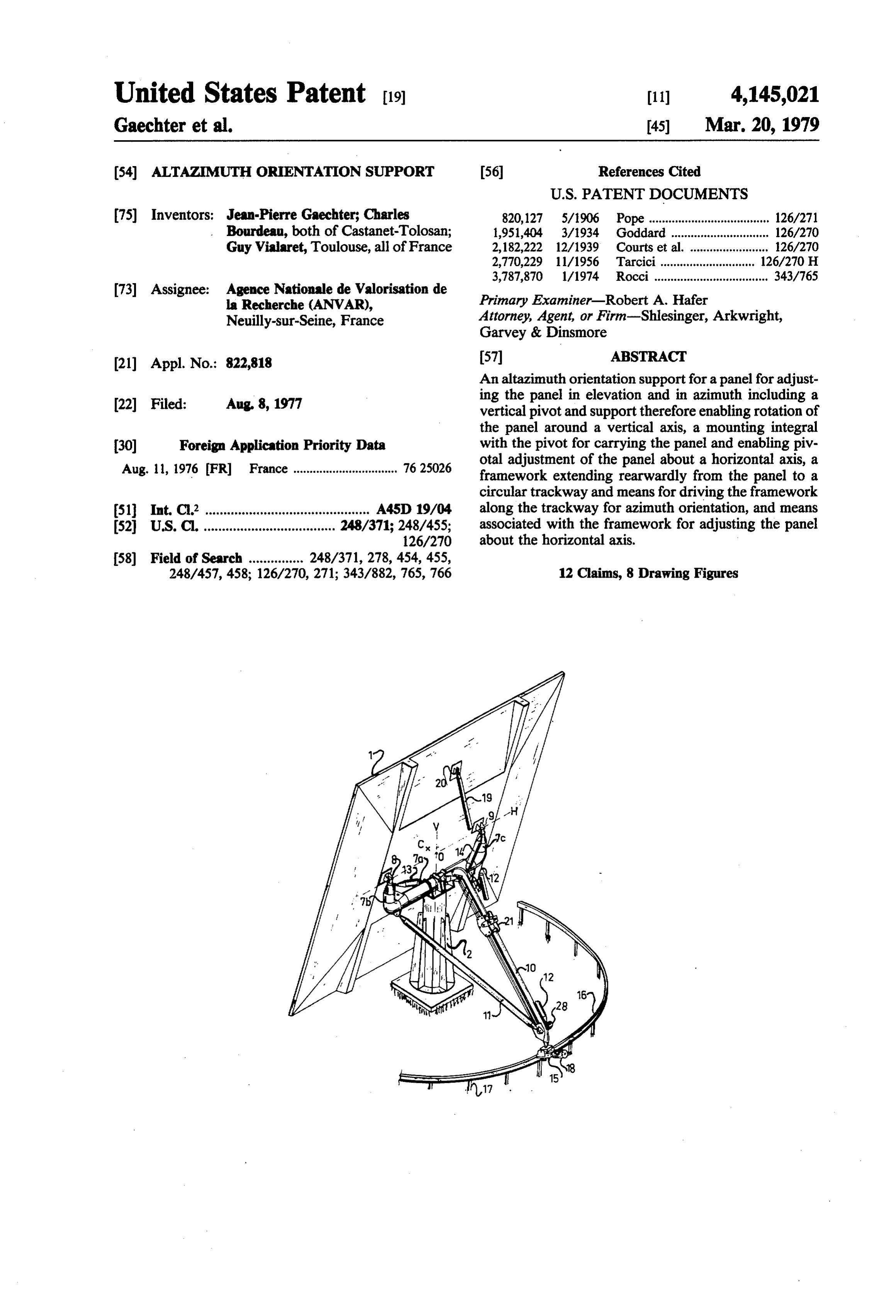
The invention concerns an altazimuth orientation The present invention proposes a remedy to the support for orientation of a panel in elevation and in 5 aforementioned faults of known orientation supports. azimuth. This support can particularly but not exclu One object of the invention is particularly to furnish sively be a heliostat support to properly orient a reflect an orientation support which is beneficial and has the ing panel of flat or parabolic form, in order to direct the following features: the capacity to furnish high preci solar rays toward an objective to be radiated or heated, sion regulation, the capacity to support large dimension such as photochemical, heat, etc., cells. 10 panels, and reduced cost.
The present heliostat supports can be classified in Another object of the invention is to furnish a support three categories. Some possess a central pivot which which can be controlled in closed loop. For this, the supports the panel to be oriented and a central control altazimuth orientation support according to the inven system arranged at the head of this pivot to assure the tion, intended to orient a panel, particularly a heliostat movements of the panel in elevation and in azimuth. 15 panel, in elevation and in azimuth, comprises an essen This control system frequently comprises an endless tially vertical pivot, a stationary central column pro screw and rack drive. This type of support is suitable for vided with support means for said pivot adapted to small panels but cannot be applied in practice when the guide it in rotation around a vertical axis V, a mounting panel exceeds surface dimensions on the order of 20 to which is integral with the pivot and carries the panel by 30 m, because its central control system is not rigid and 20 means of articulation means which are adapted to give cannot be adapted to support great forces, of the type it the faculty to pivot around a horizontal axis H, a transmitted by large surface panels (forces due to wind, framework provided for maneuvering in azimuth, ex weight, etc...). These supports can be improved by pro tending toward the rear of the panel and rigidly con viding their control system with a planet reduction gear trolled on the aforementioned mounting to define the without play and with high torque. However, the cost 25 orientation of the panel around the vertical axis V, of the unit then becomes very high, while the power guide means of the rear end of the framework on a necessary for its control also become very high. circular trajectory centered on the vertical axis V, drive In another type of heliostat, the panel is divided into means for this end along this trajectory, an elevation several small panels which are individually supported; maneuvering framework, articulated on the panel to these panels are coupled together by a mechanical sys 30 there define the panel orientation around the horizontal tem (rod linkage system or the like) which generates axis H, and provided at its opposite end with a movable their movement and orients them in elevation and in foot adapted to be able to displaced along the frame azimuth. This mechanical system is complex and very work for maneuvering in azimuth, and finally drive cumbersome and does not allow high precision regula means to drive this movable foot along the framework tion; besides, the number of panels which can be con 35 for maneuvering in azimuth.
trolled with such a system is limited in practice. Also, Thus the assembly of the panel and of the mounting there is the problem of the shadow of one panel shading which carries it is supported by the vertical pivot sup the other, which limits the possible orientation of the ported by the central column. The framework for ma panels and does not permit reflection of the grazing neuvering in azimuth exerts on the guide means only incidence beams. tangential forces which permit definition of its position Also, another type of heliostat exists, in which the in azimuth, and it is not necessary that these means be support comprises a horizontal triangular base, intended adapted to support high constraints. These guide means to be displaced on a circular rail for the azimuth angle can comprise a circular stationary rail centered on the regulation. The panel is supported by this horizontal vertical axis V and rolling means carried by the rear end base and can be pivoted vertically around one side of 45 of the framework and guided by the rail. The move the base to effect the regulation of the angle of eleva ments of the panel are effected around vertical axis V tion. In this type of heliostat, the rail supports the total and around horizontal axis H, which are defined on the weight of the panel and of the structure. The precision one hand by the column and its pivot, and on the other of its form and of its position according to the 3 axes of hand by the mounting and its articulation means; the the space is determinant to attain good precision in the 50 circular rail does not impose its own design at the time regulations of the orientation of the panel; these charac of execution of these movements, and its form and its teristics require that this rail be very rigid, be realized position need not be very precise according to all of the with very low tolerances, and that its setting be exe axes of the space. It can however serve as advantageous cuted very carefully on the chosen site. Moreover, support for an absolute coder in azimuth. whatever be the precautions taken, even a slight modifi 55 Preferably, the support means with the column, and cation of the state of the terrain (sinking or other) is the articulation of the panel on the mounting, are prejudicial to the precision. It should also be noted that adapted such that the vertical axis V, defined by these in this type of heliostat the center of the panel is greatly support means, and the horizontal axis H, defined by displaced in the course of the rotation cycle. Under this articulation, are coplanar, and the secant area of these conditions it is difficult to control the movements 60 these axes is in proximity with the center of the panel. of the panel in closed loop, because the ray reflected by This panel is thus balanced relative to the pivot, which the center of the panel, which each instant gives the supports it, and its center is displaced only slightly on a mean orientation of the reflected beam, cannot be used small radius sphere centered at the intersection of axes as reference to detect the variations of orientation of the Hand V. In application to heliostats or analogous appli incident beam and simply to deduce from it in correc cations, it is possible to position a sighting element tions to be effected. Moreover, it is difficult to find which is intended to receive the reflected rays issuing another reflected ray adapted to constitute such a refer from the central zone of the panel, in order to control ence. This type of heliostat is thus of necessity con the movements of the panel in closed loop.
Page 10
According to a preferred embodiment, the frame external bolts to allow for variation of the used length work for maneuvering in azimuth is formed by a rigid and thusly the verticality of pivot 5. structure, particularly tubular, in tetrahedral form, pro It is to be noted that for control of the movements of vided with a long element extending toward the rear in the panel in open loop, the verticality of the pivot along the axial plane of the panel; the movable foot of the axis V must be precisely regulated, because the move framework for maneuvering in elevation is connected ments are generated by taking absolute spatial refer to this long element in order to be displaced along it. ences, by determining relative to these references the This framework for maneuvering in elevation can be trajectory of the sun, and by deducing from that the very simply constituted of a bearing, particularly tubu absolute rotations to execute. On the contrary, if the lar, situated in the axial plane of the panel. The movable 10 control is assured in closed loop, this verticality does foot preferably includes means for rolling, guided by not have to be regulated so precisely, since the correc the framework for maneuvering in azimuth. tions do not refer to absolute axes, but are adjusted by Besides, the rolling means at the rear end of the successive advances while referring to the variations of framework for maneuvering in azimuth are preferably orientation of a reflected ray collected by a sighting connected to it by a connection system which is adapted 15 element.
to give said rolling means a freedom of movement rela Besides, pivot 5 is integral with a tubular mounting 7 tive to the framework, in the plane perpendicular to the which includes a horizontal portion 7a connected in the rail, and to rigidly connect said framework and said middle to the pivot, and two upward angled ends 7b and rolling means along the direction tangential to the rail. 7c. Each end is provided with an articulation joint 8 or Thus, except for the forces of friction, no force is ex 20 These9, which carries panel 1 with interposition of caps. erted on the circular rail in the radial plane and its small ends are adapted such that the articulations 8 and imperfections are translated by local variations of the 9 define a horizontal axis H of panel rotation, intersect radius of the curve or the height and are not prejudicial ing effected with vertical axis V. The movements of the panel to the precision to be attained in orientation of the 25 are axes. The around the intersection point 0 of these two center C of the panel is near this point, since panel. The rail can be implanted on site without diffi culty, and small differentials of the terrain, which can itthickness is moved away only by a distance formed by the of the panel.
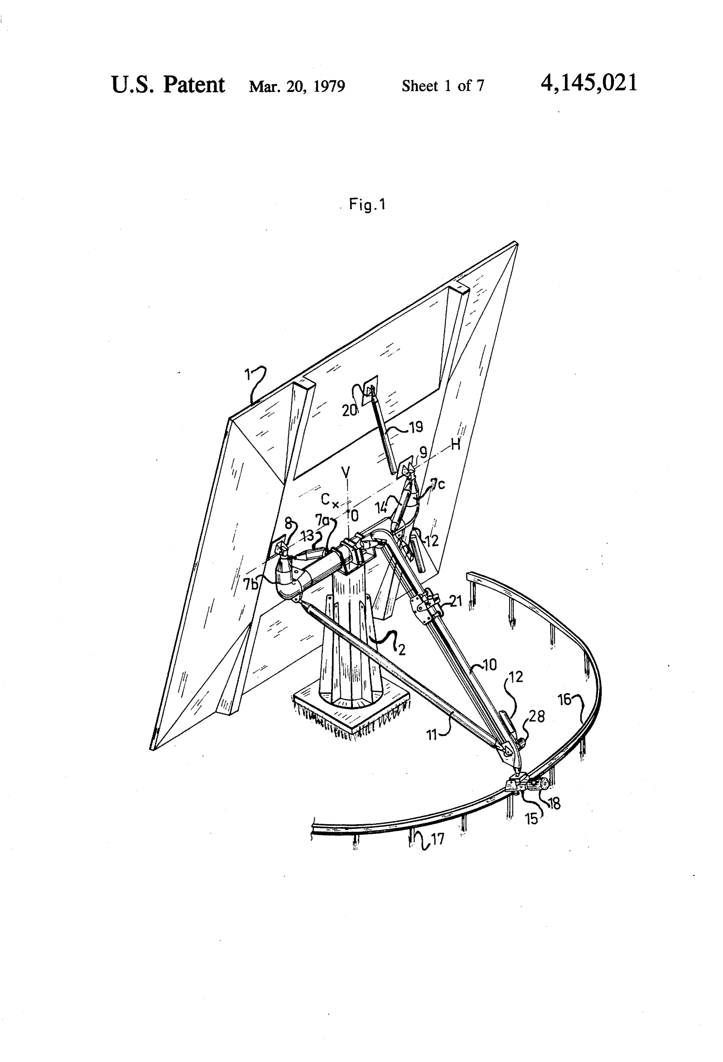
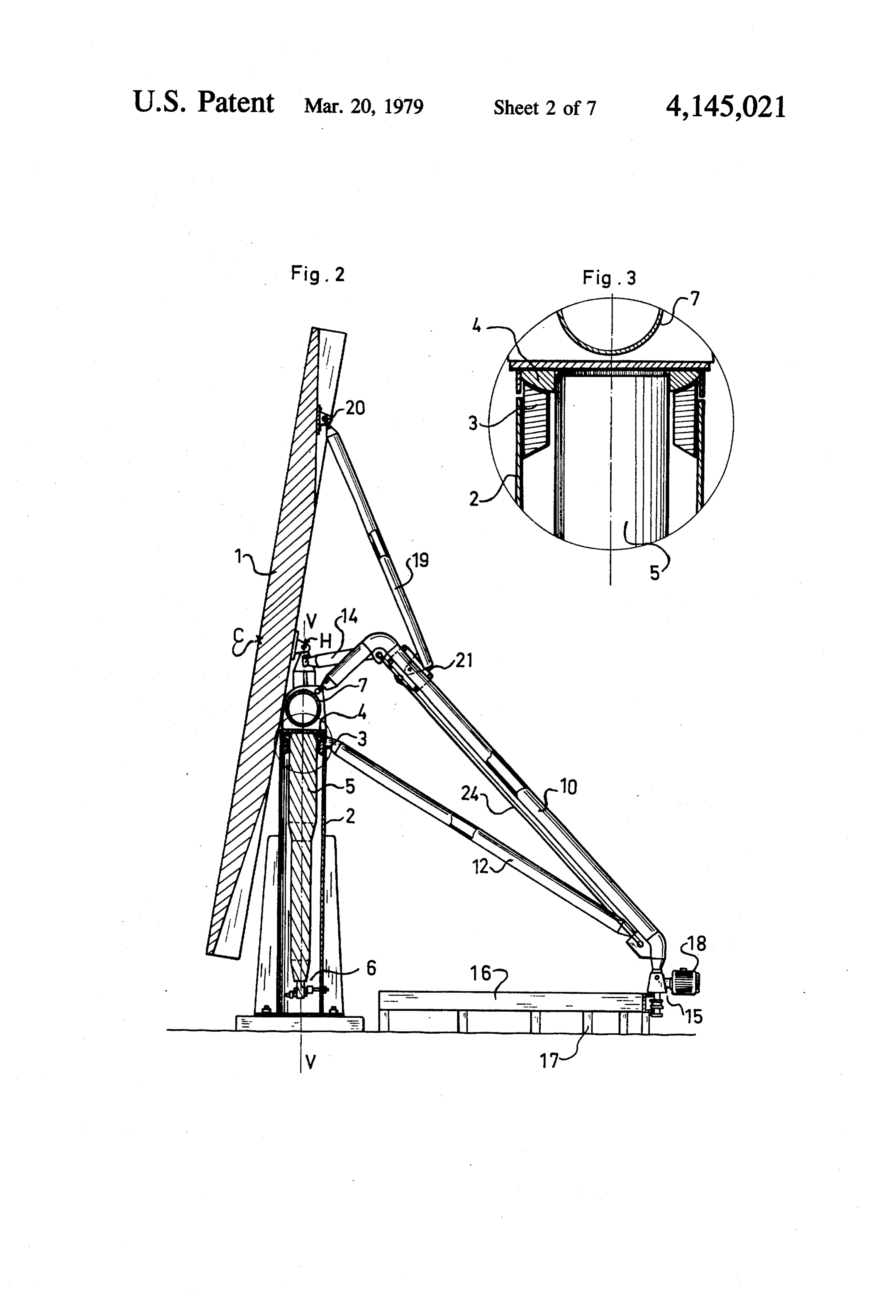
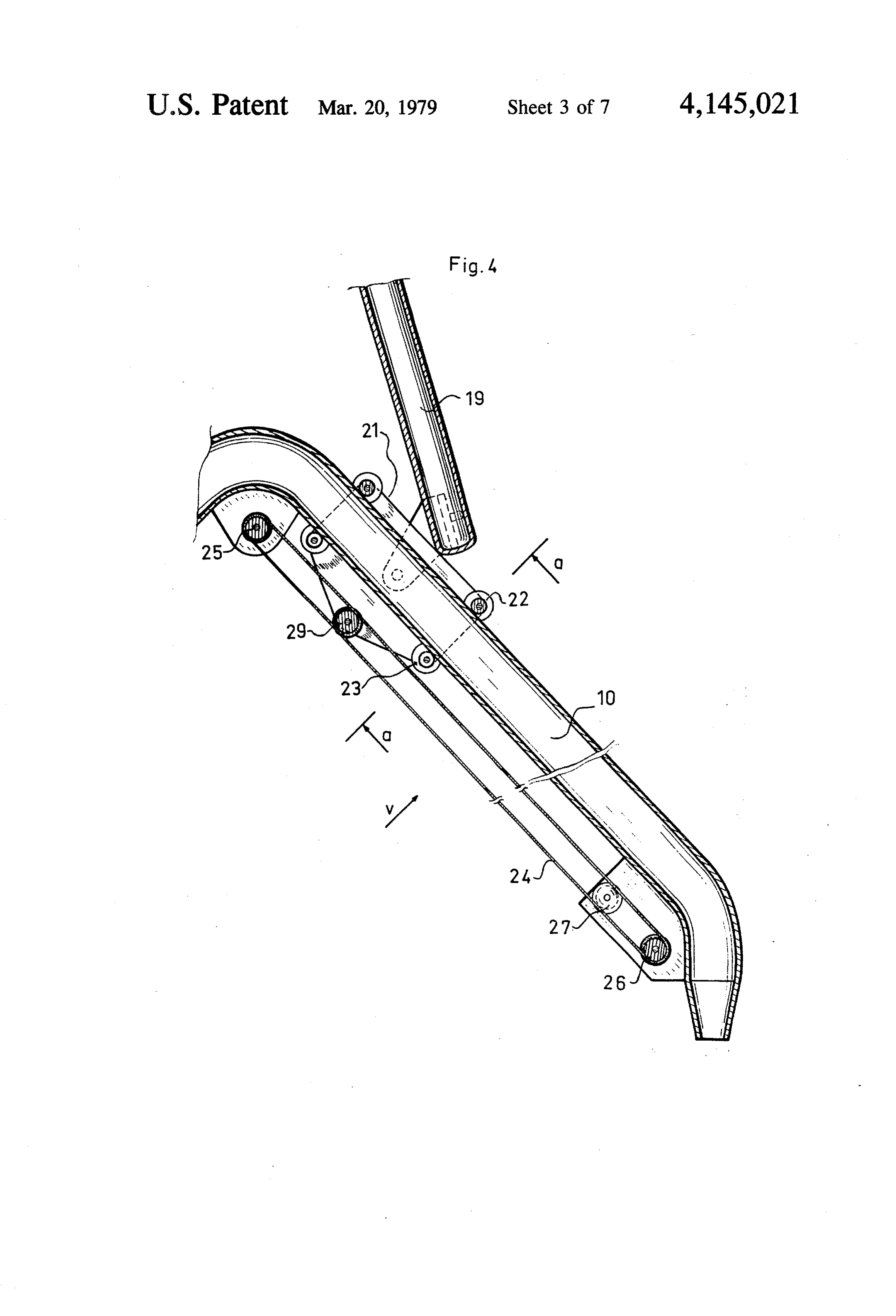
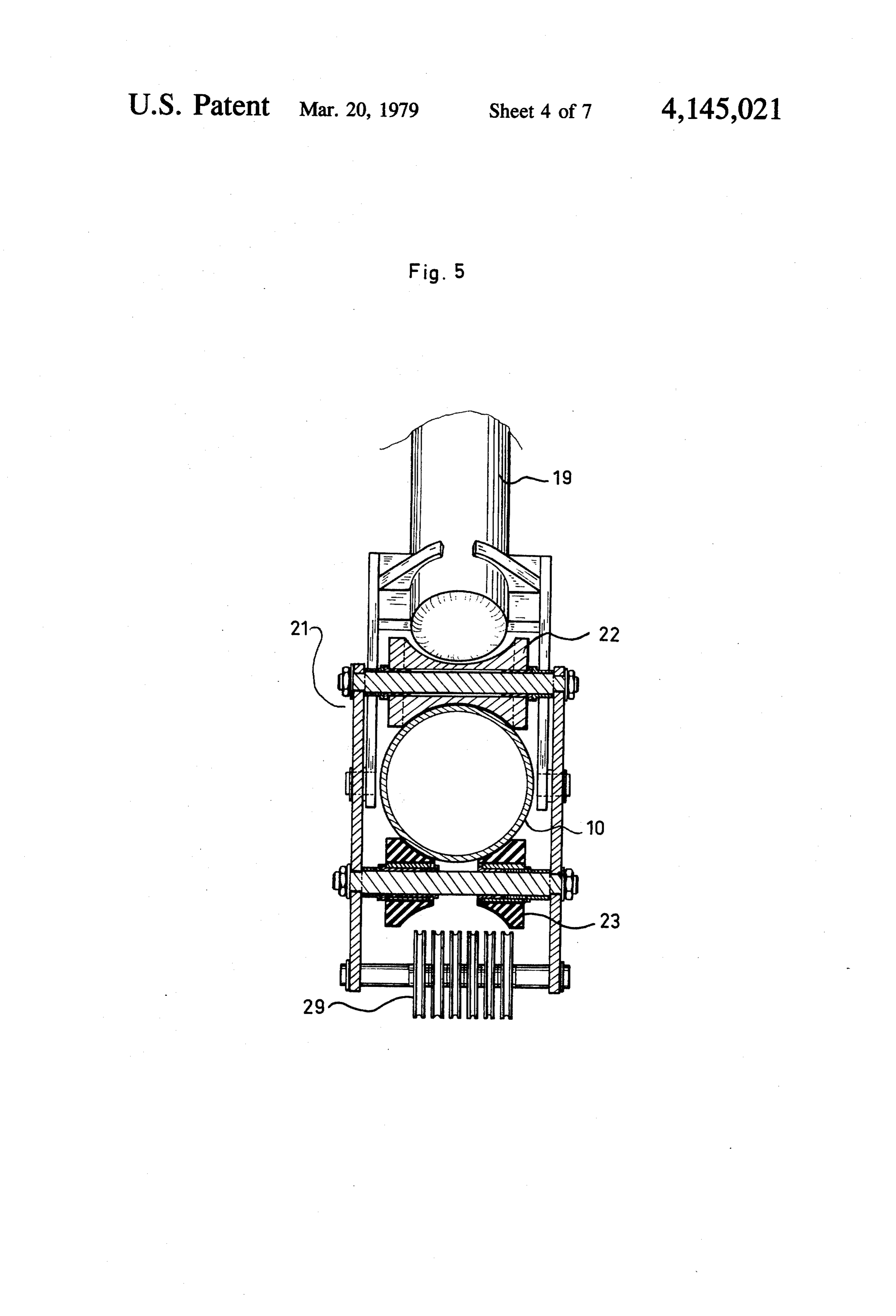
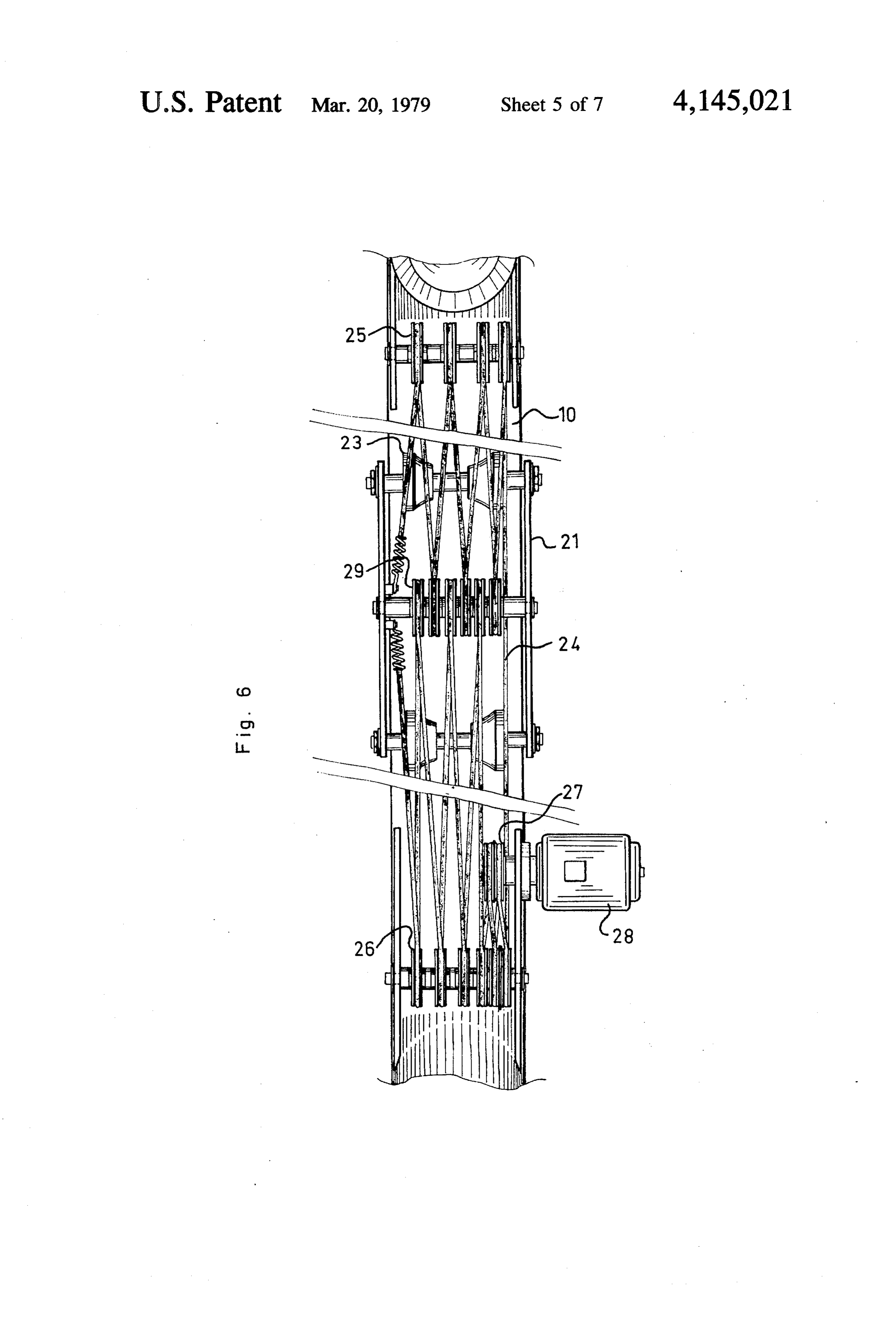
locally modify its height, are of no concern. Thus, the orientation support according to the inven Other characteristics, objects and advantages of the tion lends itself invention are disclosed in the following description, in 30 sighting element tocancontrol in closed loop, because the reference to the attached drawings, which show a pre receive the rays reflected by the without be positioned difficulty to central zone of the ferred embodiment and one variation which are nonlim iting. panel which is displaced on a small diameter sphere. FIG. 1 is a perspective of one embodiment, with forThe mounting 7 is rigidly connected to a framework maneuvering in azimuth, formed in the example by partial cross sections through certain elements. 35 five tubular elements: one rear axial element 10, two FIG. 2 is a vertical cross section through the assem rear lateral elements 11 and 12, and two anterior lateral bly, along the axial plane. elements 13 and 14. In FIG. 1, these elements are ar FIG. 3 is a cross section of a detail from FIG. 2. ranged according to the sides of a trihedon, in such a FIG. 4 is a partial cross section showing an assembly fashion as to form a rigid indeformable structure. They which is included in this embodiment. are connected by their anterior parts to mounting 7 in FIG. 5 is a cross section showing a detail of this em such a manner that the assembly constituted of the bodiment. mounting and this structure is of itself an indeformable FIG. 6 is a view from the bottom in the direction of rigid assembly. The connections are assured on the set axis V of this embodiment. off axes, and the axial element 10 includes an angled FIG. 7 is a partial perspective view of a different 45 anterior portion which assures its connection with the assembly. mounting.
FIG. 8 is a partial perspective view showing a varia The rear end of axial element 10 is connection system tion of this assembly. which will be described hereinafter, to a carriage 15 The altazimuth orientation support shown in the which is adapted to be moved along a circular rail 16; drawings provides that a flat panel 1 can pivot for orien 50 this rail is anchored on the ground by means of small tation in azimuth and in angle, so that the reflected posts 17 and is centered (i.e., has its center of curvature) beam reaches a stationary objective whatever the posi on the V axis. It has a transverse section in U form. tion of the sun. Carriage 15 can be drawn along rail 16 by drawing This support includes a hollow column 2, comprising means described hereinafter, including a direct drive a steel reinforced sheath, bolted down on a concrete 55 motor 18. The position of carriage 15 along the rail mass. The column is essentially vertical, without ex defines the position of the framework for maneuvering tremely precise adjustment of its verticality. in azimuth 10, 11, 12, 13, 14 around the axis V, and thus As seen in FIGS. 2 and 3, this column has a spherical that of mounting 7 and consequently, the azimuth angle bearing 3 at the top, on which rests a convex part 4 of of the panel.
ball head of conjugate spherical form. This ball head 60 Also, the orientation support includes a tubular rod part is fastened to a pivot 5 which penetrates into hol 19, situated in the vertical axial plane of the panel and low column 3. This pivot is thus sustained by the col connected to it at the top by an articulation 20. The foot umn by the interposition of bearing 3, and its verticality of this rod is movable along axial element 10 and is for can be regulated precisely by regulation means 6 which this purpose articulated on a carriage 21 which is guided permit adjustment of the position of the base of said 65 by this element.
pivot. The regulation means can include three tighten FIGS. 4 and 5 show this carriage including four par ing rings around pivot member 5, spaced angularly at tially cylindrical grooved runners, 22 and 23; the top 120, which also engage on the wall of the sheath by runners 22 are steel and precisely define the position of
Page 11
the carriage along element 10, while the bottom runners: 1. An altazimuth orientation support for permitting 23 are coated with an elastic layer which takes up the orientation of a panel in elevation and in azimuth com play and assures constant engagement of the top run prising a substantially vertical pivot, a stationary central ners on element:10. .. . . . . .. .. . column having support means for said pivot and Carriage 21 can be moved along element 10 by a 5 adapted to guide said pivot in rotation about a vertical double pulley system extending along this element. This axis, a mount integral with said pivot for carrying said system includes a cable 24 which effects several-cycles. panel so that the center of said panel is adjacent said around between two tackles 25 and 26 articulated on vertical axis, said mount including articulation means element:10; the strands of the cable are wound at the between said mount and said panel for enabling said bottom part on a winch 27 driven by a direct drive 10 panel to pivot about a horizontal axis, a movable frame motor 28. These strands are wound on the one hand on work for maneuvering said panel in azimuth extending loose pulleys 29 which are integral with the carriage, rearwardly from said panel and being rigidly fastened and the ends of the cable are hooked to this to assure its on said mount for defining the panel orientation about being pulled. This pulley system with several strands said vertical axis, means for guiding the rear end of said permits reduction of the torque which has been devel 15 framework on a circular trajectory centered on said oped by the motor, and is to increase the precision with vertical axis, means for driving the rear end of said which carrage 21 is positioned along element 10, due to framework along said guiding means, frame means asso the reduction effect. Thus, high precision angle regula ciated at one end with said articulation means and hav tion is obtained with low cost elements.
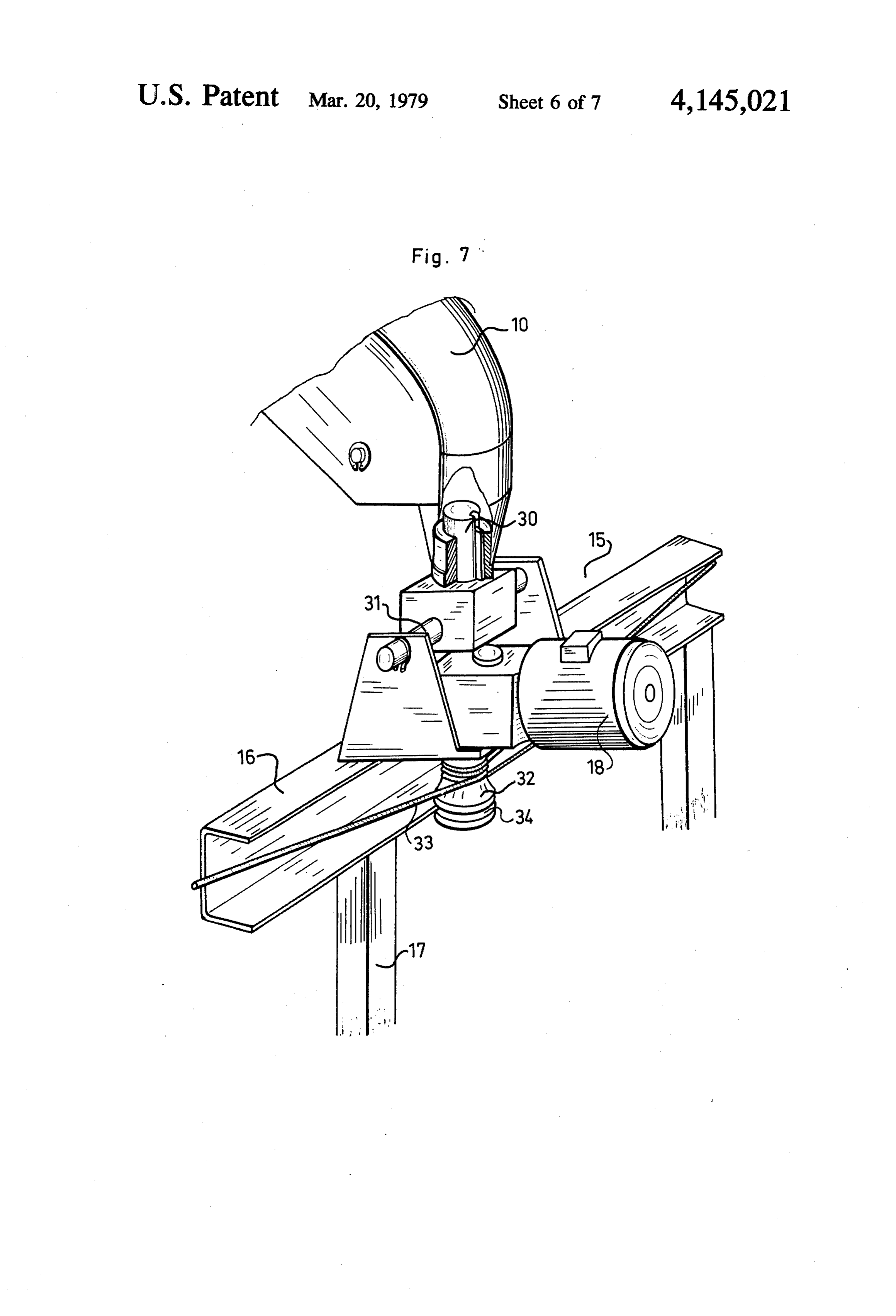
Also, FIG. 7 shows an embodiment of carriage 15, 20 work ing at its other end a foot movable along said frame with means to pull it along rail 16, and the connection ing said for maneuvering in elevation, and means for driv system by which this carriage is connected to axial said panelfoot in along said framework for maneuvering elevation.
element 10.
This connection system confers a freedom of clear port 2. Orientation support as in claim 1, wherein the sup ance in the radial plane, perpendicular to the direction 25 panel means of the column, and the articulation means of of rail 16; it comprises an essentially vertical slide ele the of the mounting are equipped so that the verti ment 30 to permit essentially vertical clearance (in the Zontal axis defined cal axis H, by the support means, and the hori example, a vertical axis keyed into a bearing which is coplanar, and the Zonebyofthese
H, defined articulation means, are intersection of these axes is integral with element 10), and a journal 31 parallel to situated in the vicinity of the center of the panel. the tangential direction of the rail to permit pivot in the 30 3. Orientation support as in claim 1, wherein the perpendicular plane in this direction. This system is thus framework for maneuvering in azimuth is formed of a adapted to absorb the variations of radius of curve of rigid structure in the form of a tetrahedron, provided the rail or variations of height of the rail. Of course, with a long element extending toward the rear in the these variations are slight, and the degree of play ac ceptable is on the order of few millimeters. 35 axial plane of the panel, and the movable foot of said In FIG. 7, the direct drive motor is prepared to cause frame means is connected to this long element to be a winch 32 to rotate, around which is wound cable 33, displaced along with it.
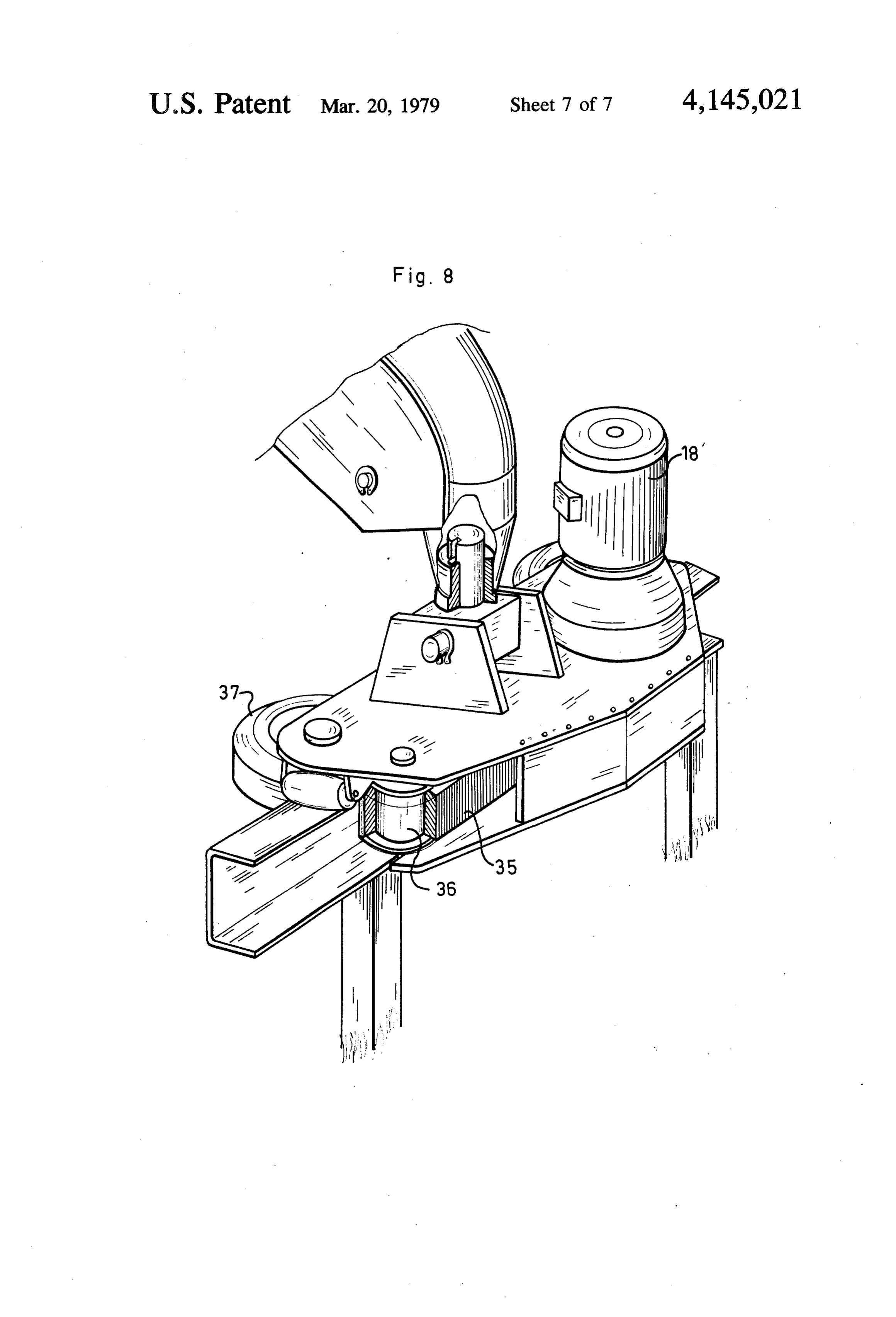
extending along the rail; this cable is guided by the rail 4. Orientation support as in claim 1, wherein the and applies winch 32 against one wing of the rail along guide means of the rear end of the framework for ma which it can roll because of a groove 34 in the winch. In neuvering in azimuth include a stationary rail of circular such a system, the carriage is guided by the rail in the form, centered on vertical axis, and roller means carried course of its displacement, but it is cable 33 and not the by this rear end and guided by the rail. rail which directly defines the azimuth angle: sliding 5. Orientation support as in claim 4, wherein the rol along the rail remains without influence on the degree ler means, situated at the rear end of the framework for of this angle. 45 maneuvering in azimuth, are connected to this frame FIG. 8 shows another embodiment of pulling means work by a connection system adapted to give said roller for the carriage. Here it is moved by a friction system means a freedom of movement relative to the frame engaging against the rail and adapted to roll without work in the plane perpendicular to the rail and to con sliding along the rail; this system is caused to rotate by nect said framework and said roller means rigidly along a direct drive motor 18'. This system here includes a 50 the direction tangential to the rail. serrated belt 35 extending between two pulleys 36 of 6. Orientation support as in claim 5, wherein the con which one is moved by the direct drive motor. Pressure nection system connecting the end of the framework runners 37 apply the belt against the rail. and its roller means includes an essentially vertical slide The orientation support structure disclosed permits, element, permitting an essentially vertical clearance of on the one hand, definition with great precision of the 55 the roller means, and a journal parallel to the tangential aximuth angle and the elevation angle which character direction of the rail, permitting a pivoting of these roller ize the orientation of the panel by a decentralized drive means in the perpendicular plane to this tangential di of the panel, and on the other hand, reduction of the rection.
necessary motive power; the direct drive motors used 7. Orientation support as in claim 4, wherein the drive can be direct drive motors of present quality available at means of the framework for maneuvering in azimuth reduced cost on the market. The different elements, include a direct drive motor provided to drive a winch particularly the circular rail, can be manufactured with in rotation around which is wound a cable, extending customary tolerances and assembled without particular along the rail and guided by it.
precautions. 8. Orientation support as in claim 4, wherein the drive Of course the invention is not limited to the terms of 65 means of the framework for maneuvering in azimuth the preceding description, but includes also all of the include a direct drive motor adapted to drive a friction variations. system in rotation coming in contact against the rail and What is claimed is: equipped to roll without sliding against it.
Page 12
9. Orientation support as in claim. 1, wherein said equipped to be moved by a winch powered by a direct drive motor on said frame means.
frame means is formed by a rod situated in the axial 11. Orientation support as in claim 1, wherein the plane of the panel, and the movable foot of the rod support means include the stationary column including includes roller means guided by the framework for 5 a spherical bearing, fastened to said column and on maneuvering in azimuth. - which rests a convex ball head part of conjugated 10. Orientation support as in claim 9, wherein the spherical form, connected to the pivot. drive means of the roller means of the movable foot of 12. Orientation support as in claim 10, wherein the the rod include a double pulley system, extending along 10 stationary column is a hollow column in which pene trates said pivot, means for regulating the base position said frame means, and provided with a cable attached to of said pivot for adjusting the verticality of said pivot. said rolling means, and said pulley system being
Provenance
- Collection
- Cited prior art
- Original PDF
- patentimages.storage.googleapis.com →
- Filed
- 1977-08-08
- Pages
- 12
- Method
- pdftotext (the PDF's own text layer) + pdftoppm 300dpi page scans
- Source
- Google Patents bibliographic record
- Granted
- 1979-03-20
- Inventors
- Jean-Pierre Gaechter; Charles Bourdeau; Guy Vialaret; Agence National de Valorisation de la Recherche ANVAR
- Transcribed from
- patentimages.storage.googleapis.com →