patent · US6220337
Heat pipe circuit type thermal battery
24 April 2001
Page 1 — bibliographic record
(12) United States Patent (10) Patent No.: US 6,220,337 B1 Chen et al. (45) Date of Patent: Apr. 24, 2001
(54) HEAT PIPE CIRCUIT TYPE THERMAL Primary Examiner Ira S. Lazarus BATTERY Assistant Examiner Tho Duong (74) Attorney, Agent, or Firm-Dougherty & Troxell (76) Inventors: Shi-Li Chen, 4th Floor, No. 23-9, Alley 48, Lane 493, Wan Ta Road, Taipei; (57) ABSTRACT
Ming-Jer Hsiao, No. 397, Fu Hsing
Road, Nan Tou City 540, both of (TW) Disclosed is a heat pipe circuit type thermal battery which Notice: Subject to any disclaimer, the term of this can Store, release, and efficiently utilize heat and/or cold. patent is extended or adjusted under 35 The thermal battery mainly includes an energy Storing U.S.C. 154(b) by 0 days. chamber for containing phase change medium to Store or release heat energy via the change of the phase change (21) Appl. No.: 09/066,711 medium between the Solid and liquid phases, a heat pipe circuit formed from a plurality of vertically arranged parallel (22) Filed: Apr. 27, 1998 heat pipes to guide working fluid flowing therein and (51) Int. Cl." .......................... F28D 17/00, F28D 19/00 transfer energy through phase changes of condensing and (52) U.S. Cl. ..................................... 165/10 A; 165/104.17 boiling of the working fluid, and two heat eXchangers (58) Field of Search ............................. 62/185; 165/10 A, Separately Serving as heat Source and heat Sink. Heat energy 165/104.17; 126/361 contained in flowing fluid in the heat-Source heat eXchanger is transferred to the working fluid in the heat pipe circuit and (56) References Cited then Stored in the energy Storing chamber. On the other hand,
and transferred to the heat-sink heat eXchanger via the heat 2,911,513 : 11/1959 MacCraken ........................ 165/10 A pipe circuit. With Superior thermal conductivity, the heat 4,119,143 :: 10/1978 Robinson, Jr. .... ... 165/10 A 4,258,696 : 3/1981 Gopal ............ ... 165/10 A pipes can automatically and effectively Store or release 4,598,694 : 7/1986 Cromer . ... 126/361 energy just like a battery without the need of electrical 4,607,498 : 8/1986 Dinh ....................................... 52/185 power.
4,609,036 9/1986 Schrader ............................ 165/10 A * cited by examiner 2 Claims, 15 Drawing Sheets
Page 2
Drawing sheet — no readable text.
Page 3
Drawing sheet — no readable text.
Page 4
Drawing sheet — no readable text.
Page 5
Drawing sheet — no readable text.
Page 6
Drawing sheet — no readable text.
Page 7
Drawing sheet — no readable text.
Page 8
Drawing sheet — no readable text.
Page 9
Drawing sheet — no readable text.
Page 10
Drawing sheet — no readable text.
Page 11
Drawing sheet — no readable text.
Page 12
Drawing sheet — no readable text.
Page 13
Drawing sheet — no readable text.
Page 14
Drawing sheet — no readable text.
Page 15
Drawing sheet — no readable text.
Page 16
Drawing sheet — no readable text.
Page 17
HEAT PIPE CIRCUIT TYPE THERMAL BRIEF DESCRIPTION OF THE DARWINGS
BATTERY
The above and other objects of the present invention as
BACKGROUND OF THE INVENTION well as the Structure and principles applied to achieve these objects and many other functions of the present invention
The present invention relates to a thermal battery formed can be best understood by referring to the following detailed from a heat pipe circuit and functioning like a battery to description of the preferred embodiments and the accompa Store or release heat or cold energy. Heat or cold energy is nying drawings, wherein
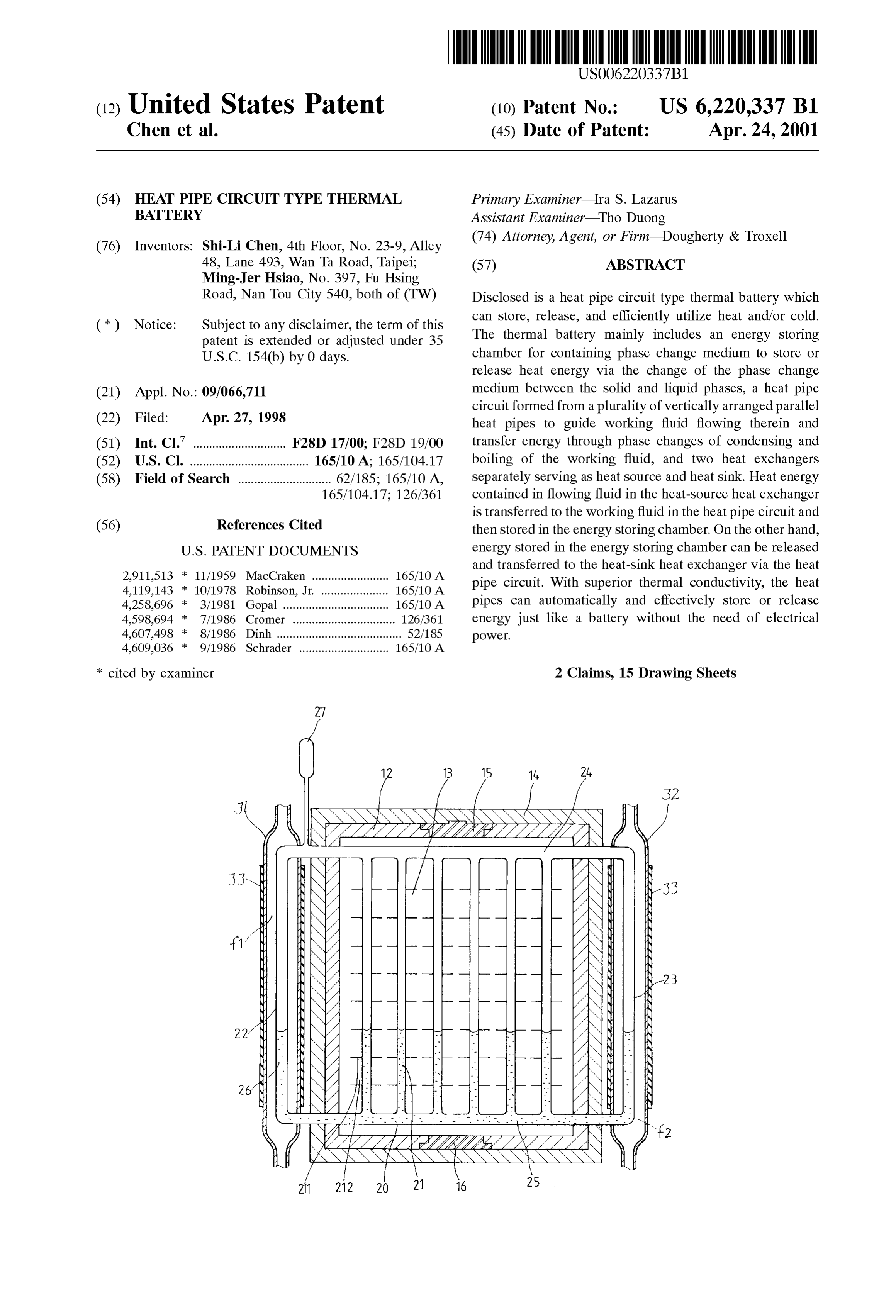
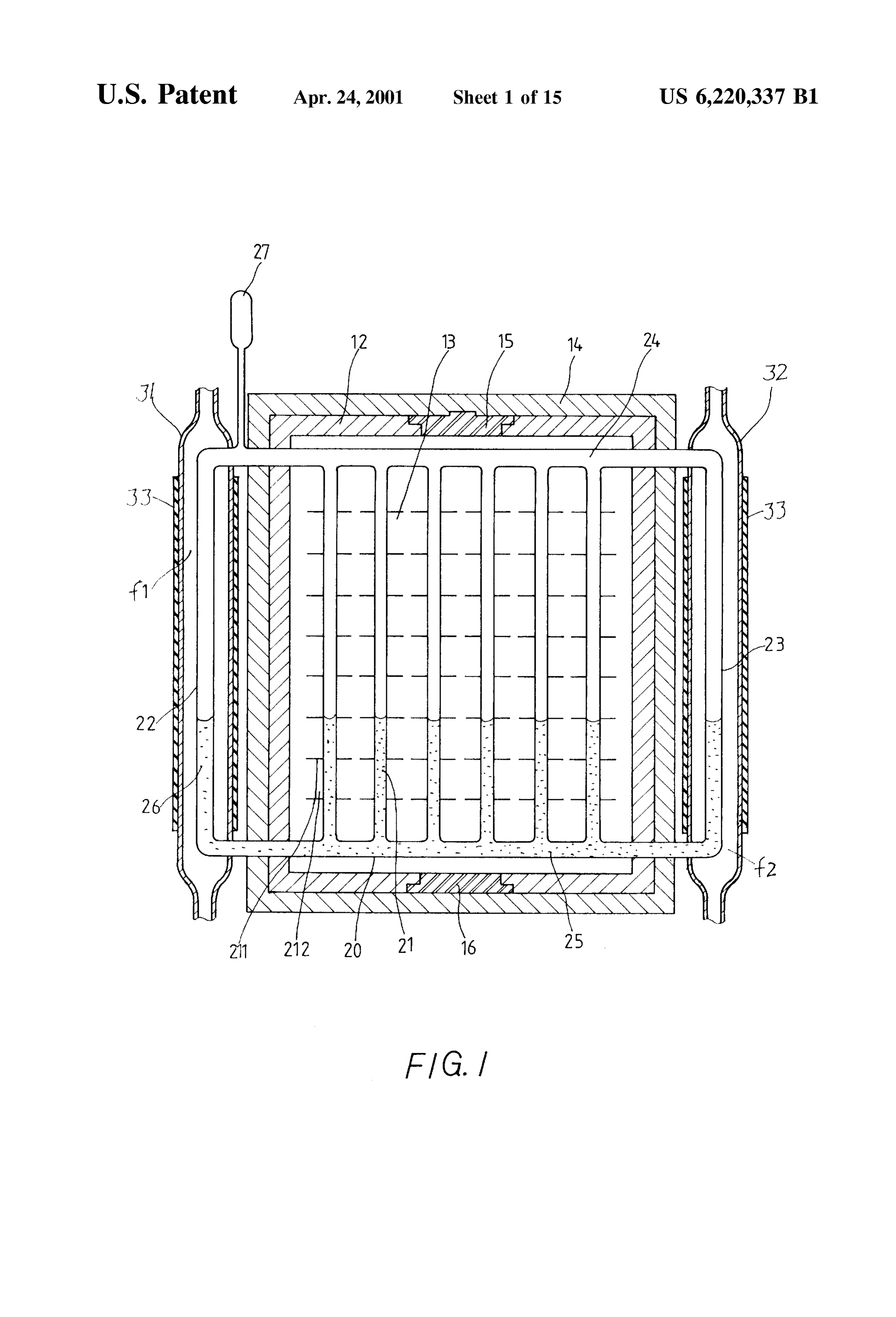
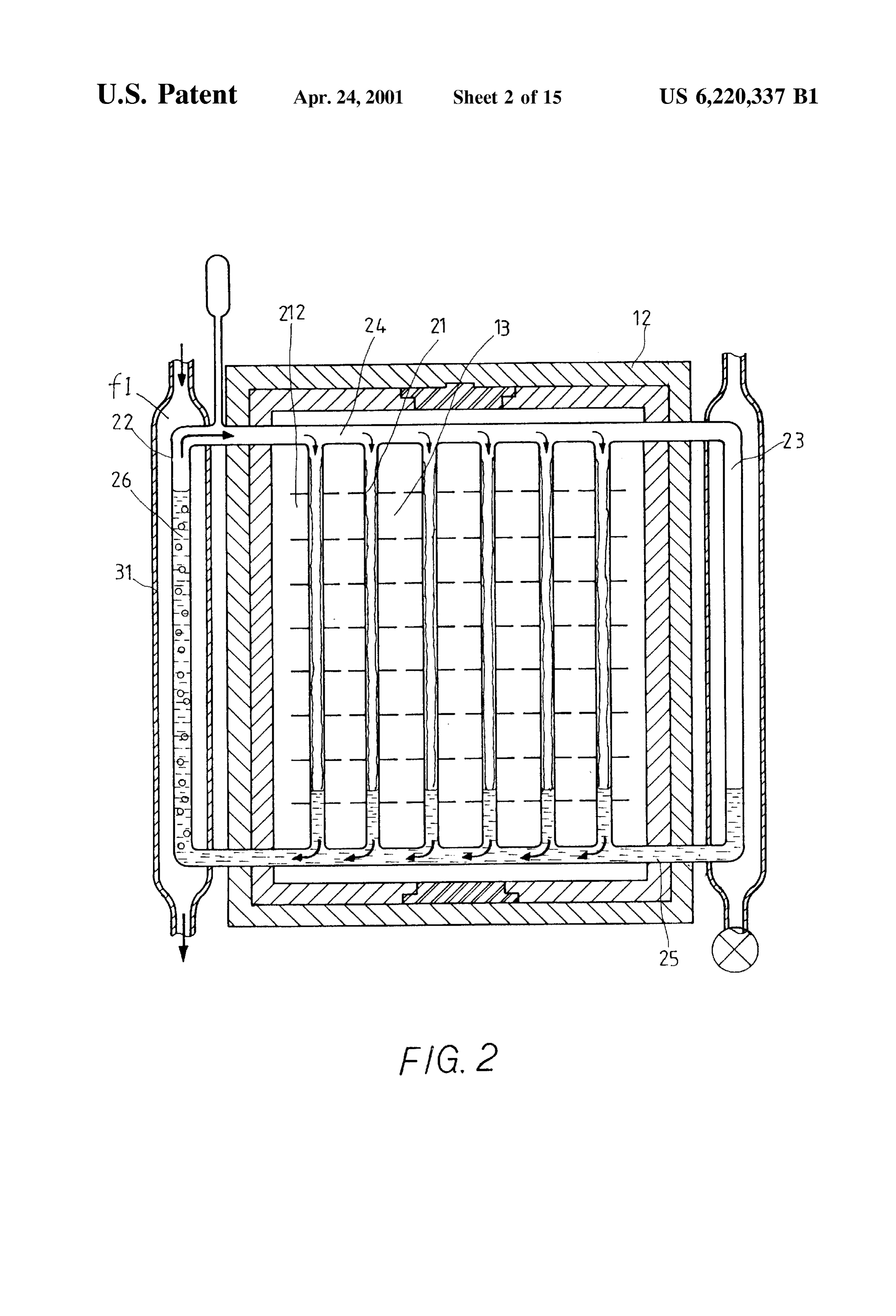
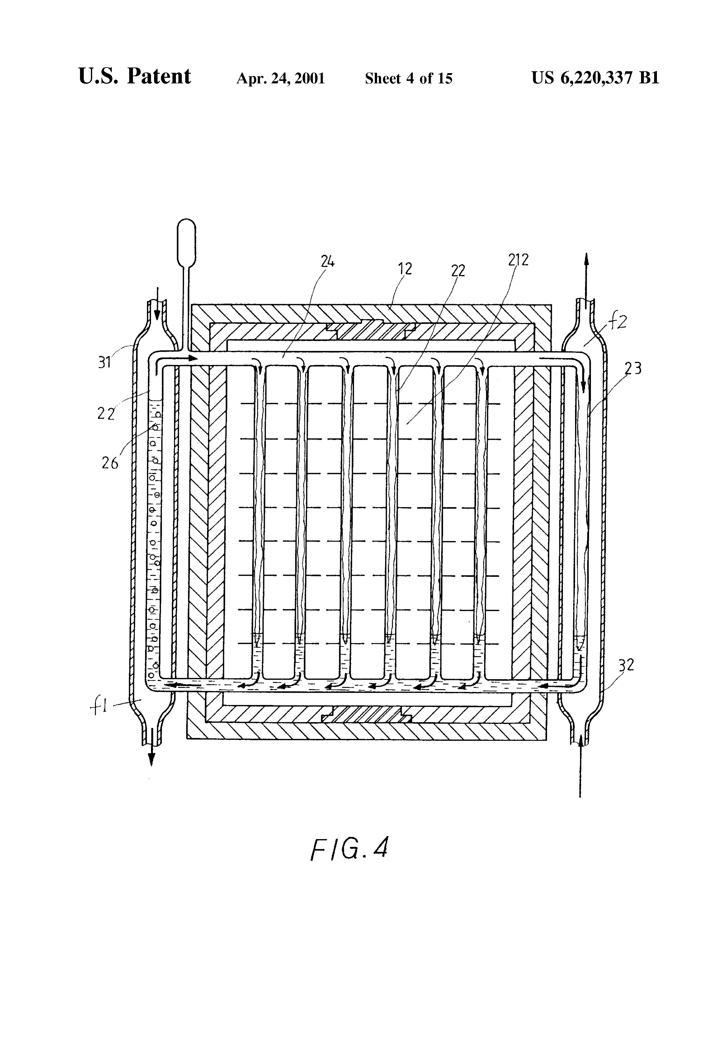
Stored in the thermal battery and can be released for use later. FIG. 1 is a sectional view of the present invention; Or, in the event too much heat or cold energy is Supplied FIG. 2 is a Sectional view explaining the working prin during the utilization of heat or cold energy, extra and ciples of the present invention for heat Storage; unused heat or cold energy can be Stored in the thermal FIG. 3 is a Sectional view explaining the working prin battery. On the contrary, in the event insufficient heat or cold energy is Supplied, additional heat can be provided by the ciples of the present invention for heat release; thermal battery for use. With the thermal battery of the 15 FIG. 4 is a Sectional view explaining the working prin present invention, energy can be fully utilized. ciples of the present invention when the Supplied heat is It is known that a lot of energies, either heat or cold larger than the required heat;
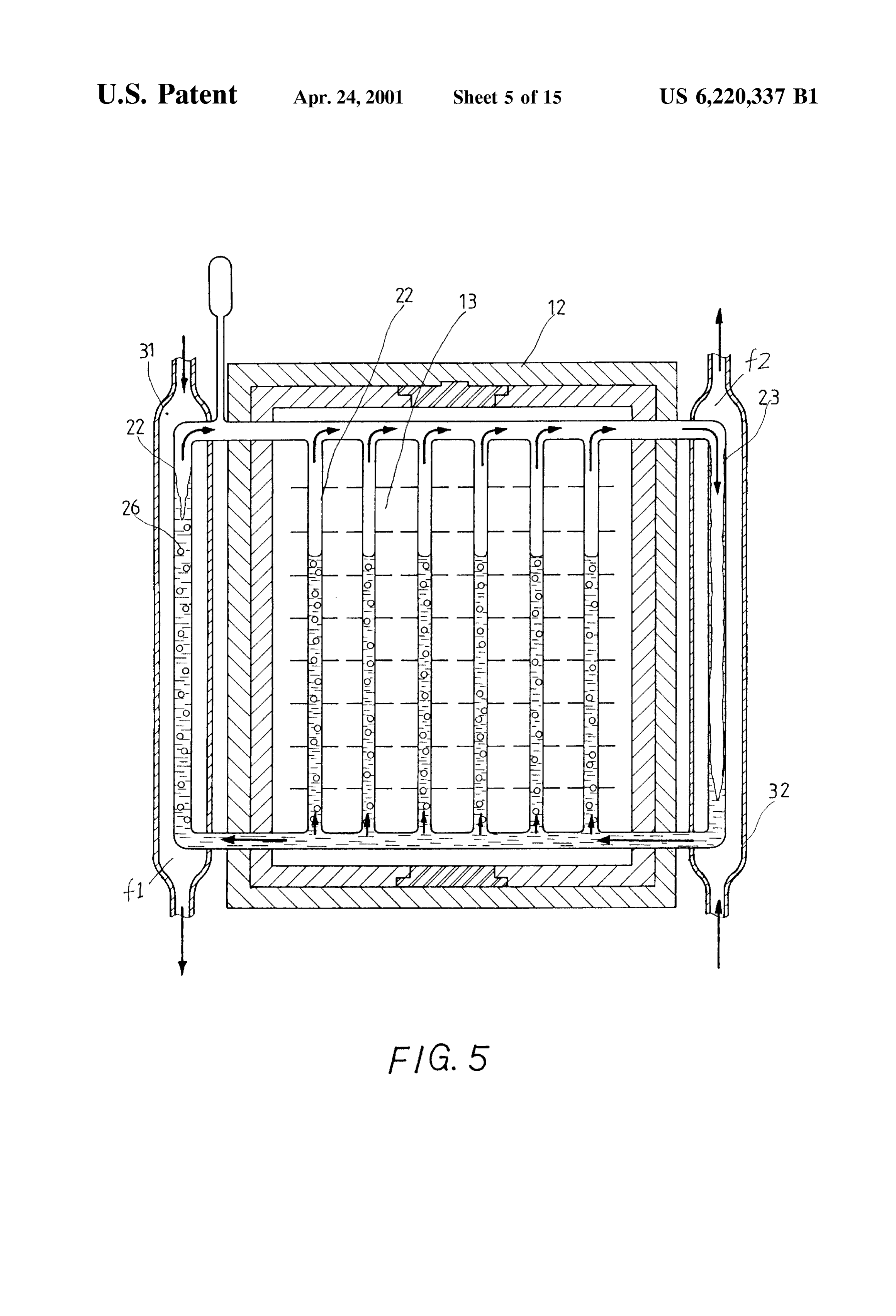
energy, are not effectively used or Stored during utilization FIG. 5 is a Sectional view explaining the working prin of the energies and therefore lose in the atmosphere and ciples of the present invention when the required heat is form waste heat which causes environmental pollution, poor larger than the Supplied heat;
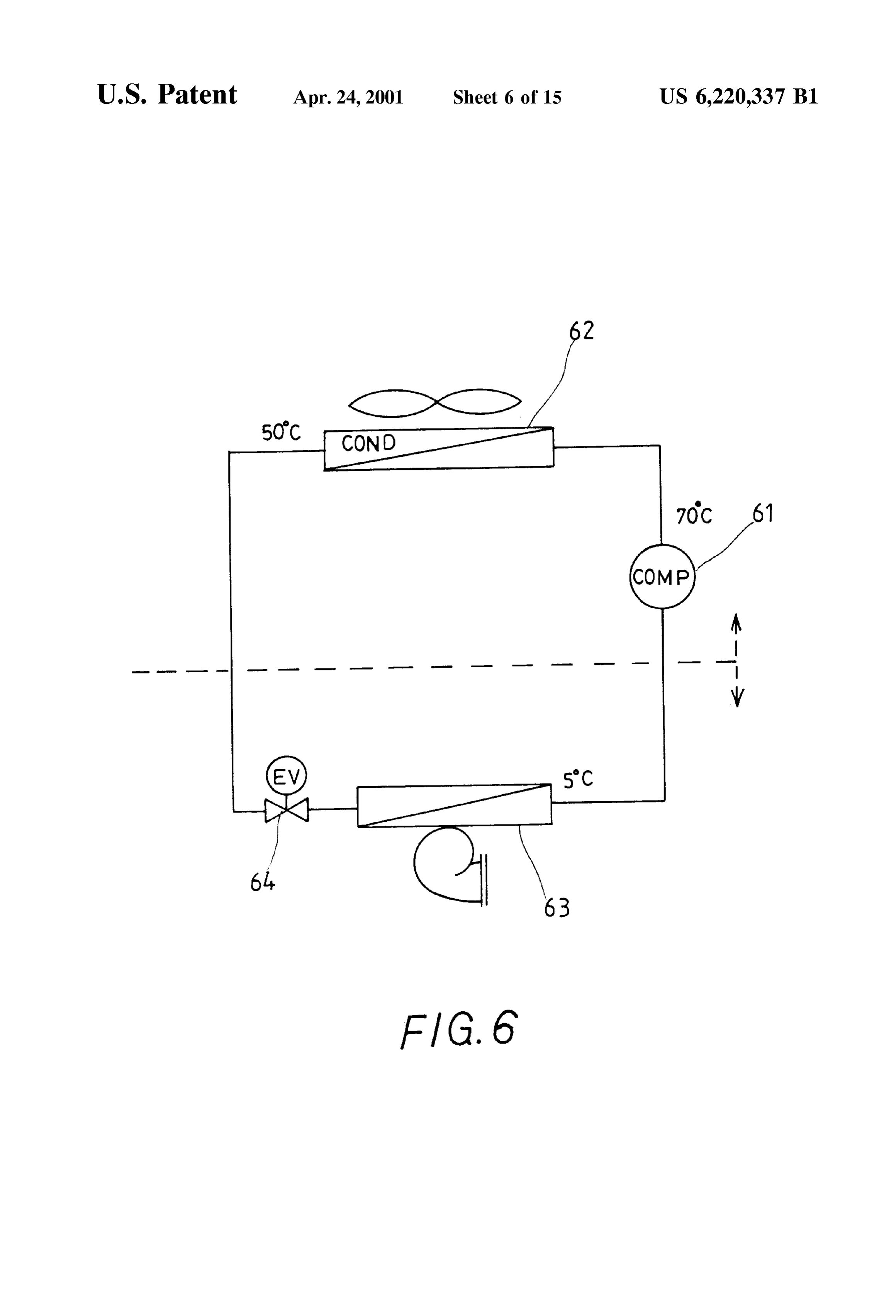
working efficiency of equipment, and undesirable waste of FIG. 6 illustrates a conventional air-cooled direct energy. Proper recuperation, Storage, and utilization of the expansion air-conditioning System;
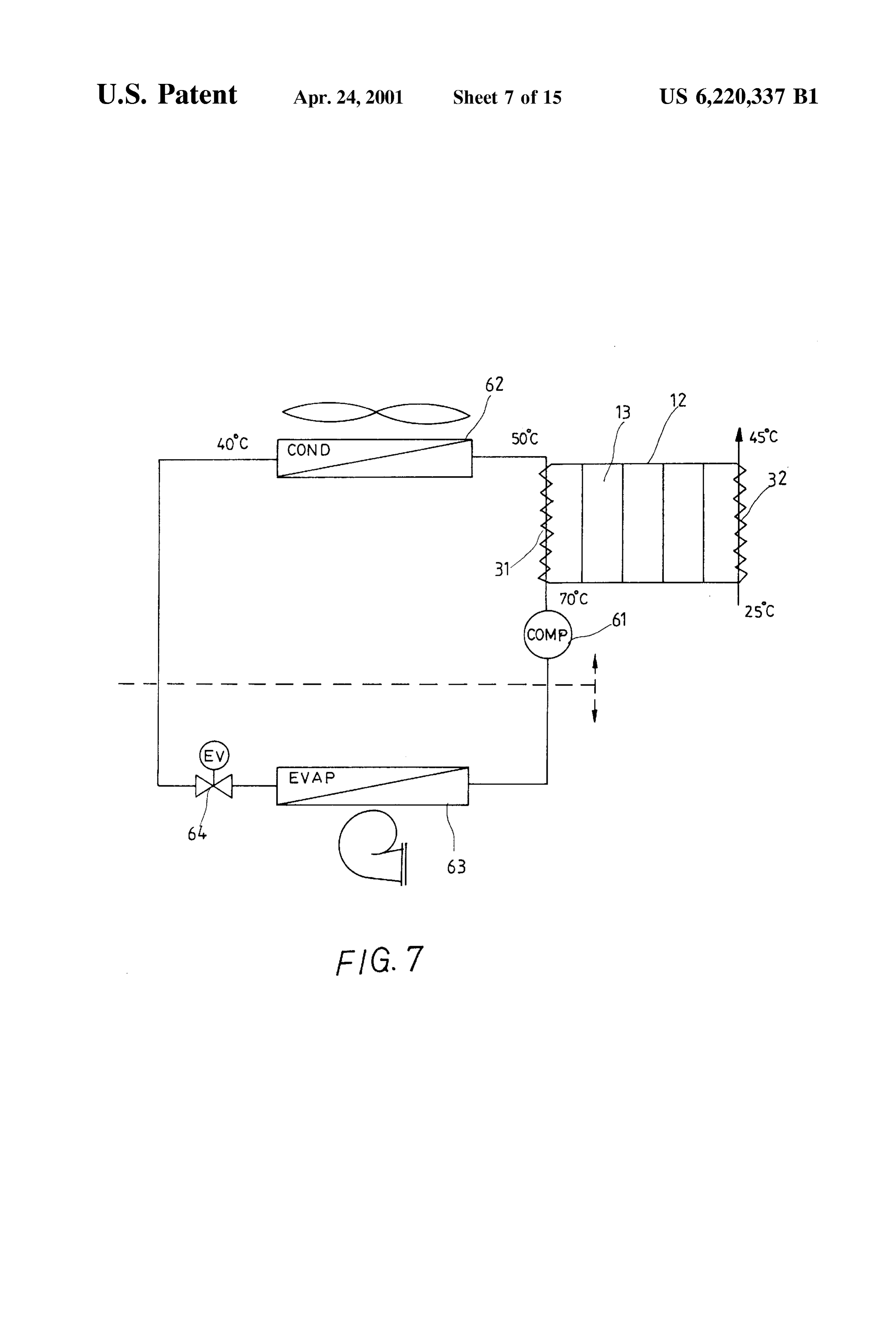
otherwise lost heat or cold energies will not only minimize FIG. 7 illustrates the application of the thermal battery of possible environmental pollution but also enhance the effi the present invention by connecting it to an exhaust pipe of ciency of energy utilization and achieve the object of energy 25 a heat recuperation System;
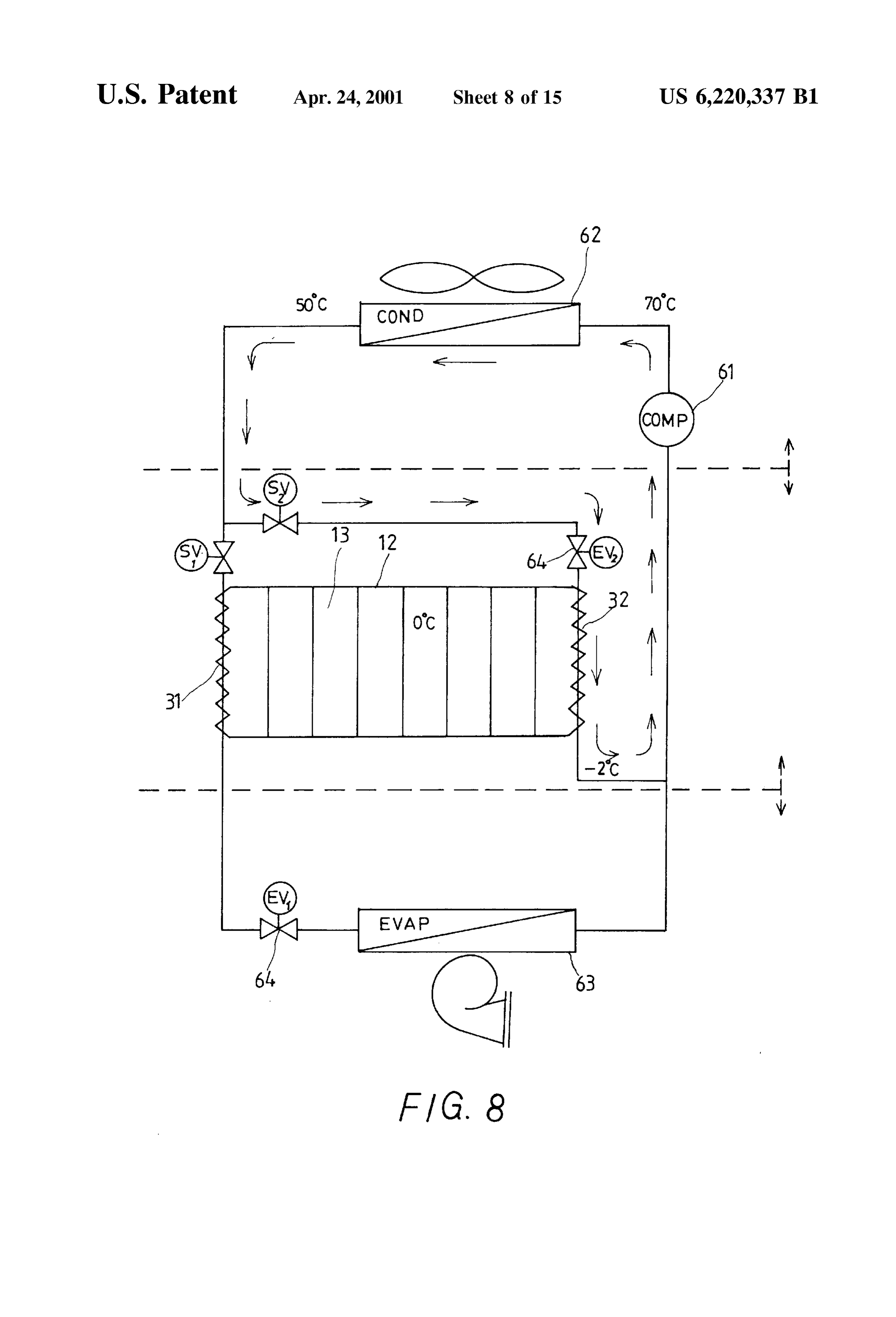
Saving. FIG. 8 illustrates the application of the thermal battery for To Store and utilize heat or cold energies, an active control cold Storage according to the present invention in the night is generally designed for a heat Storage or regeneration to charge, wherein the thermal battery uses water as the System. That is, in the System design of heat Storage, a pump phase change medium;
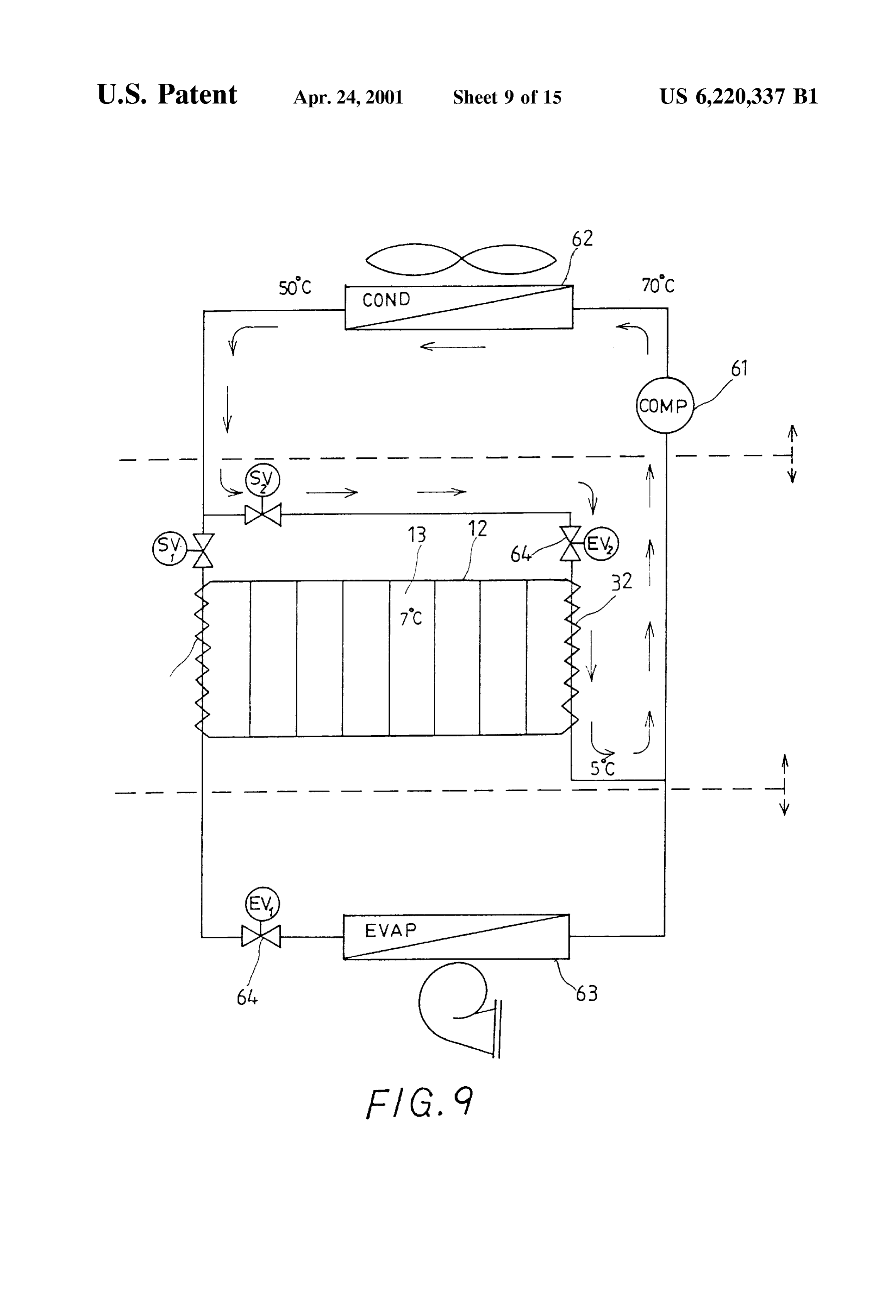
is included to transfer heat energy from a high temperature FIG. 9 illustrates the application of the thermal battery for heat Source to the heat Storage via flowing working fluid. To cold Storage according to the present invention in the night utilize the Stored heat energy, an electromagnetic valve is to charge, wherein the thermal battery uses eutectic Salt as used under control to change flow path of the working fluid, the phase change medium;
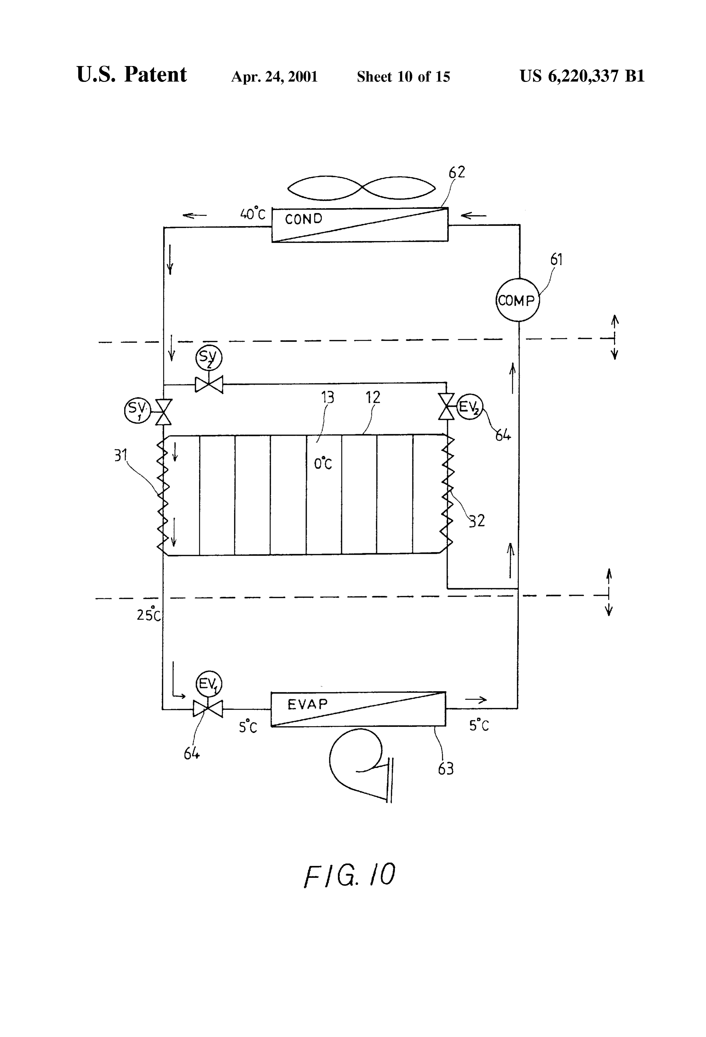
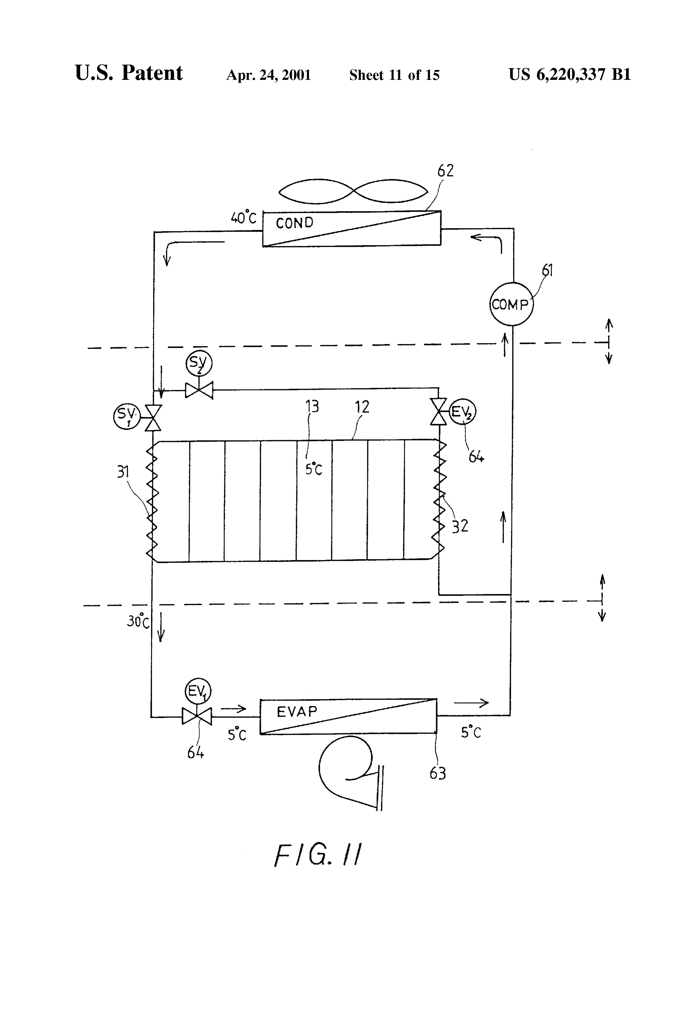
So that energy Stored in the heat Storage is released to and FIG. 10 illustrates the application of the thermal battery used by a low temperature heat Sink. There are two draw 35 for cold Storage according to the present invention in day backs found in Such type of heat Storage. First, the need of time to discharge and Subcool the refrigerant, wherein the an operating pump to transfer the working fluid and an thermal battery uses water as the phase change medium; controlled electromagnetic valve to change the energy Stor ing or releasing ability of the working fluid causes increased forFIG. 11 illustrates the application of the thermal battery operation cost and power consumption. The heat Storage 40 timecold to
Storage according to the present invention in day discharge and Subcool the refrigerant, wherein the shall be unworkable in case of a System failure. Second, thermal battery uses eutectic Salt as the phase change change of the energy Storage and release ability of the medium;
conventional heat Storage is basically relied on the System FIG. 12 illustrates the application of the thermal battery piping design and therefore only two functions, i.e. energy
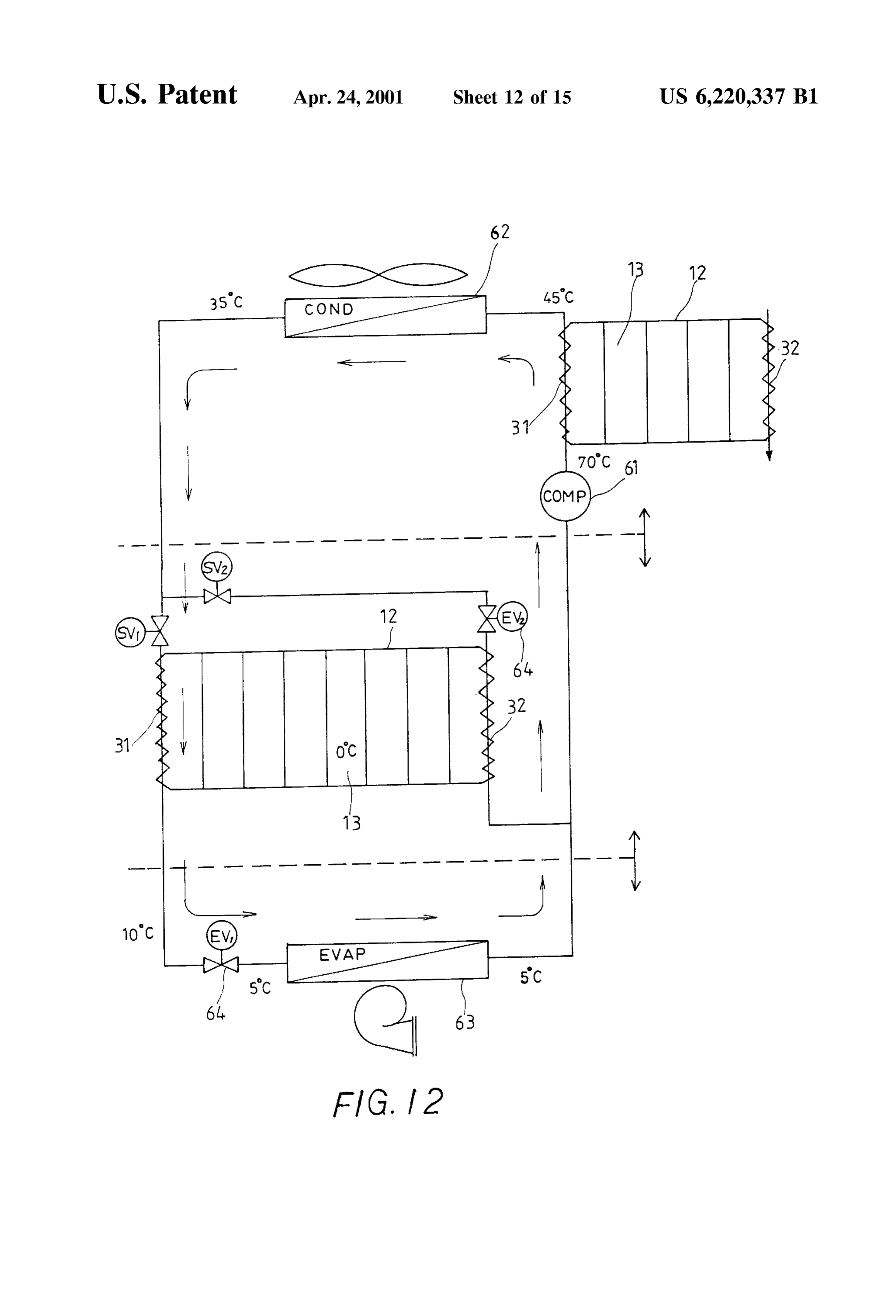
Storage and energy release, are available in its operating 45 for heat Storage and the water thermal battery for cold modes. It is impossible for both the heat supply side and the Storage at the according to the present invention to recuperate heat exhaust pipe of a compressor of an air-conditioning heat utilization side of the heat Storage to operate at the same System and to Subcool the refrigerant of the System; time during the heat utilization.
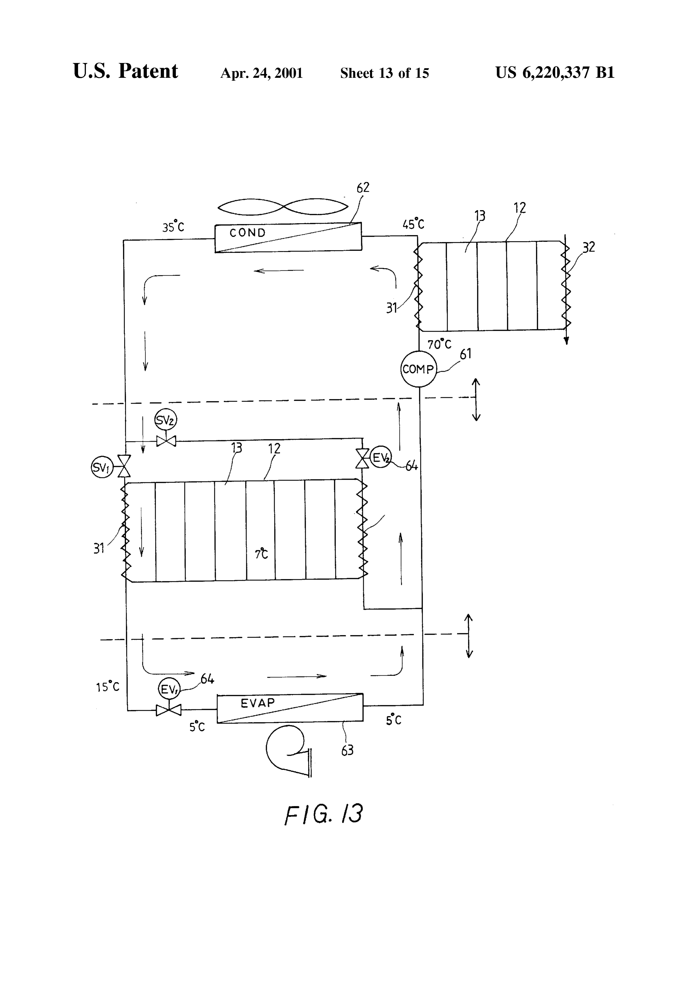
FIG. 13 illustrates the application of the thermal battery 50 for heat Storage and the eutectic Salt thermal battery for cold
SUMMARY OF THE INVENTION
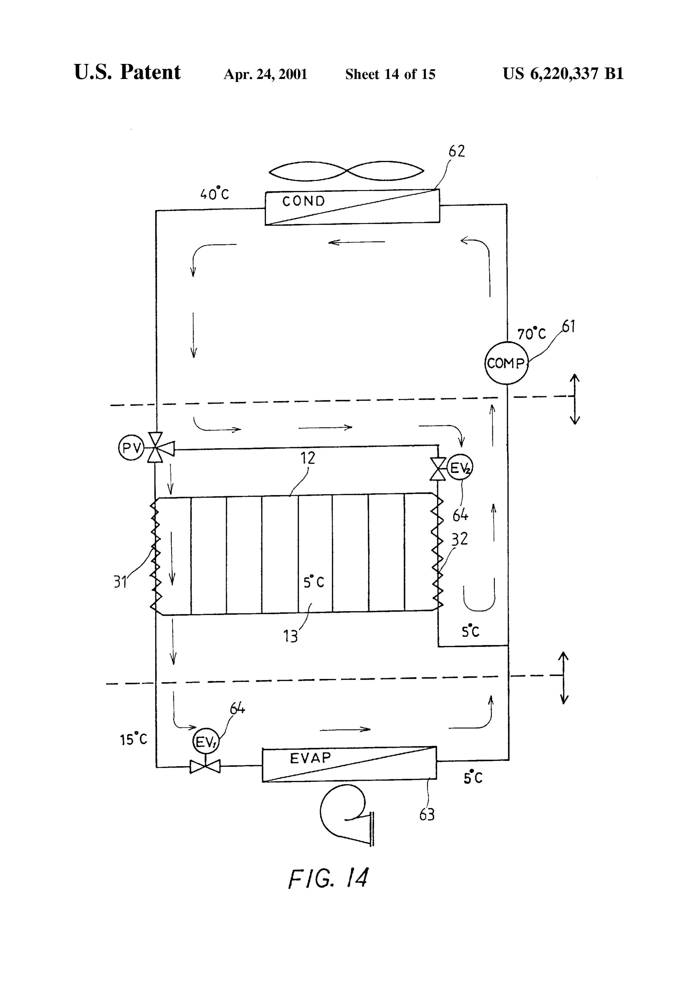
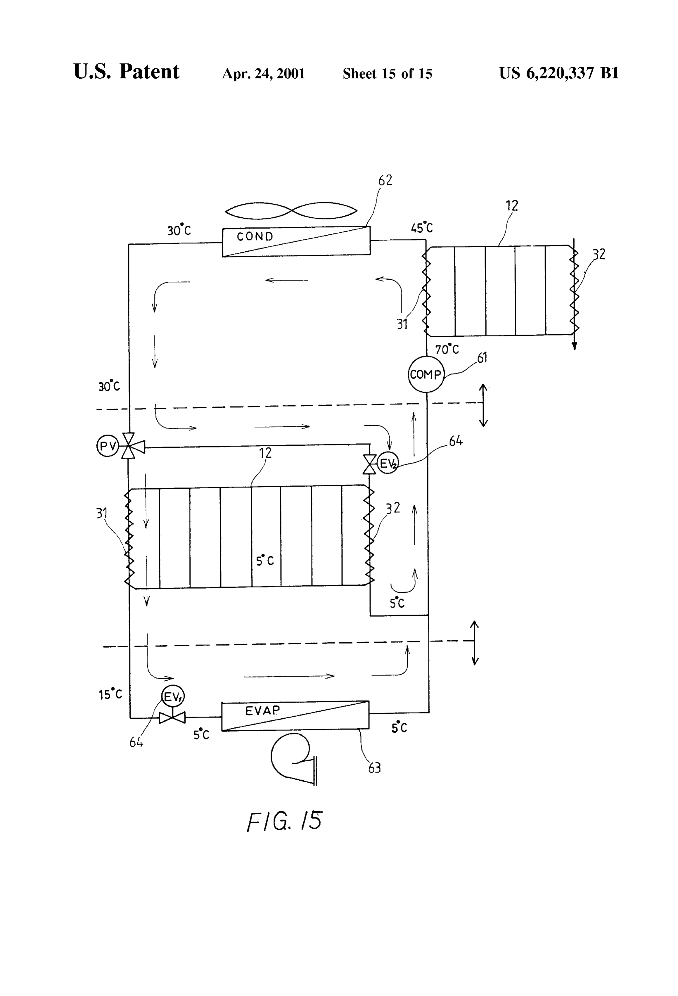
It is therefore a primary object of the present invention to Storage at the according to the present invention to recuperate heat exhaust pipe of a compressor of an air-conditioning provide a thermal battery in which a passive type of control System and to Subcool the refrigerant of the System; is adopted to eliminate drawbacks found in the conventional heat Storage and no pump and electromagnetic valve are FIG. 14 illustrates the application of the thermal battery required. Moreover, apart from Storing and releasing energy, 55 for cold Storage according to the present invention to Store the thermal battery of the present invention also allows and release cold at the same time, and operation of heat energy Supply Side and heat energy use FIG. 15 illustrates the application of the thermal battery Side at the same time. That is, during the heat energy for heat Storage and the eutectic Salt thermal battery for cold utilization, when extra heat energy that is more than the Storage according to the present invention in recuperating amount needed by the heat energy use side has been pro 60 heat at the exhaust pipe of a compressor of an air vided by the heat supply side, the heat not used by the heat conditioning System, Subcooling the refrigerant of the energy use Side may be stored in the thermal battery; and, System, and air conditioning.
when the heat energy provided by the heat Supply Side is DETAILED DESCRIPTION OF THE insufficient for use by the heat energy use Side, additional PREFERRED EMBODIMENTS heat may be supplemented by the thermal battery. On the 65 occasion the present invention is applied to provide cold Please refer to FIG. 1 in which a sectional view of a energy, it is in the form of a thermal battery for cold Storage. thermal battery according to the present invention is shown.
Page 18
The thermal battery mainly includes an energy Storing which flows upward due to its buoyancy into the upper chamber 12 and a heat pipe circuit 20. The energy Storing horizontal pipe 24 and then downward into the vertically chamber 12 is filled with phase change medium (PCM) 13, paralleled heat pipes 21 in the energy Storing chamber 12. At So that heat energy can be Stored or released via melting or this point, the gaseous working fluid condenses and releases freezing of the phase change medium 13 between Solid and heat to melt Solid phase change medium 13 into liquid liquid States. medium in the energy Storing cells 212 outside the parallel Insulating material 14 is provided to cover outside of the heat pipes 21. Since the condensed liquid working fluid has energy Storing chamber 12 to prevent heat loSS. A top cover a density much larger than that of the gaseous working fluid, 15 is provided at the top of the chamber 12 for replenishing it flows downward along inner wall surfaces of the vertical the phase change medium 13 into the chamber 12, and a heat pipes 21 under gravity and into the lower horizontal drain hole 16 is provided at the bottom of the chamber 12 for pipe 25 and then the Vertical high-temperature heat transfer draining the phase change medium 13 from the chamber 12. pipe 22 to complete one cycle of flow of the working fluid The heat pipe circuit 20 includes three parts, namely, a 26 in the heat pipe circuit 20. Heat released by the gaseous group of parallel heat pipes 21 vertically disposed inside the working fluid 26 in the vertically paralleled heat pipes 21 energy Storing chamber 12, Vertical high-temperature heat 15 during the course of condensation is absorbed by the energy transfer pipe 22 and vertical low-temperature heat transfer Storing cells 212 inside the energy Storing chamber 12 and pipe 23 Separately located at outside of the chamber 12, and upper horizontal pipe 24 and lower horizontal pipe 25 thereby into melts the originally Solid phase change medium 13 liquid. When the solid phase change medium 13 is extending between the vertical high/low temperature heat completely molten into liquid, heat continuously released by transfer pipes 22, 23 outside the chamber 12 to connect and the working fluid 26 is stored in the form of latent heat of communicate the group of Vertically paralleled heat pipes 21 fusion.
inside the chamber 12 and the vertical high/low temperature heat transfer pipes 22, 23. FIG. 3 shows the manner in which the thermal battery of The parallel heat pipes 21 have external short fins 211 25 the present invention operates to release heat energy. Please densely provided around their outer Surfaces to increase refer FIGS. 1 and 3 at the same time. When an amount of thermal conductive contact areas thereof. These short fins low temperature flowing fluid F2 flows into the low 211 also divide inner Space of the energy Storing chamber 12 temperature heat eXchanger 32 in a direction as shown by the into multiple energy Storing cells 212. The phase change arrows in FIG.3, it absorbs heat in the gaseous working fluid medium 13 becomes molten or frozen in these energy 26 inside the vertical low-temperature heat transfer pipe 23 Storing cells 212 to Store or release heat energy. of the thermal battery and is heated to have increased The Vertical high/low temperature heat transfer pipes 22, enthalpy Value. At this point, the originally gaseous working 23 outside the energy Storing chamber 12 are used to fluid 26 condenses into liquid working fluid which forms a eXchange heat with high-temperature and low-temperature thin layer of condensate along inner wall Surface of the flowing fluid, respectively. They have short fins 211 or spiral 35 Vertical low-temperature heat transfer pipe 23 and then flows flutes provided around inner and outer Surfaces to obtain downward under gravity into the lower horizontal pipe 25 enhanced heat transfer performance when the flowing fluid and then upward into the Vertically paralleled heat pipes 21. is gas (air), vapors, or liquid (water or liquid coolant). At this point, the liquid working fluid in the Vertically Adequate type and amount of working fluid 26 is filled in paralleled heat pipes 21 absorbs heat Stored in the liquid the heat pipe circuit 20. The adequate working fluid 26 40 phase change medium 13 in the cells 212 outside the heat includes, but not limited to, water and refrigerant (Such as pipes 21 and becomes boiled to produce gaseous working freon). A pressure-limit safety chamber 27 located outside fluid which flows upward due to its buoyancy into the upper the energy Storing chamber 12 is connected to the vertical horizontal pipe 24 and then downward into the vertical high-temperature heat transfer pipe 22 to timely Serve as a low-temperature heat transfer pipe 23 again to complete one room for receiving expanded working fluid 26. 45 cycle of flow of the working fluid 26 in the heat pipe circuit
High-temperature heat eXchanger 31 and low-temperature 20. Heat stored in the liquid phase change medium 13 in the heat eXchanger 32 are provided at two outer Sides of the cells 212 is released to the vertically paralleled heat pipes 21 during the course of vaporization and thereby freezes the energy Storing chamber 12 to Serve as flow passages for high originally and low temperature flowing fluid (Such as air, water, or brief, heatliquid phase change medium 13 into Solid State. In Stored in the liquid phase change medium 13 of freon), respectively, to flow therethrough. The high 50 the thermal battery is transferred to the low-temperature temperature heat transfer pipe 22 and the low-temperature working fluid 26 flowing through the vertically paralleled heat transfer pipe 23 extend through the heat eXchangerS 31 heat pipes 21 to boil and evaporate the working fluid 26 and and 32, respectively, to exchange heat with the high and low thereby freezes the liquid phase change medium 13 into temperature flowing fluid in the heat eXchangers 31, 32, Solid State.
respectively. Thermal insulating material 33 is provided 55 around outer Surfaces of the high and low temperature heat The above-described two operation modes, that is, the eXchangerS 31, 32 to prevent heat dissipation during opera energy Storage mode of Storing heat energy contained in the tion or shutoff of the thermal battery. high-temperature flowing fluid into the thermal battery (see FIG. 2 shows the manner in which the thermal battery of FIG. 2) and the energy release mode of using heat energy the present invention operates to Store heat energy. Please 60 stored in the thermal battery by the low-temperature flowing refer to FIGS. 1 and 2 at the same time. When an amount of fluid (see FIG. 3), work separately at different time. For a high temperature flowing fluid F1 flows into the high third operation mode that combines the above two operation temperature heat eXchanger 31 in a direction as shown by the modes, that is, the thermal battery operates when an amount arrows in FIG. 2, heat contained in the fluid F1 is transferred of high-temperature flowing fluid F1 flows through the to the working fluid 26 inside the Vertical high-temperature 65 high-temperature heat eXchanger 31 and an amount of heat transfer pipe 22. The working fluid 26 having absorbed low-temperature flowing fluid F2 flows through the low heat becomes boiled and produces gaseous working fluid temperature heat eXchanger 32 at the same time, the
Page 19
S 6 operating principles thereof can be explained in three dif 3. When the energy Supplied by the high-temperature flow ferent conditions: ing fluid is equal to the energy to be absorbed by the 1. When the energy Supplied by the high-temperature flow low-temperature flowing fluid: ing fluid is higher than the energy to be absorbed by the 5 it can From the principles applied in the above two conditions, low-temperature flowing fluid: be understood that when the energy Supplied by the Please refer to FIG. 4 which shows the manner in which high-temperature flowing fluid is equal to the energy needed by the low-temperature flowing fluid, the thermal battery the thermal battery of the present invention operates under shall operate to boil or evaporate the working fluid 26 only this condition. with the heat absorbed by the vertical high-temperature heat When the high-temperature flowing fluid F1 containing transfer pipe 22 from the high-temperature heat eXchanger large amount of heat flows through the high-temperature 31. The resultant gaseous working fluid 26 enters the vertical heat exchanger 31, the working fluid 26 in the vertical low-temperature heat transfer pipe 23 via the upper hori high-temperature heat transfer pipe 22 is boiled and evapo Zontal pipe 24 and then condenses. Heat released by the rated to produce large amount of vaporized working fluid 26 working fluid 26 during condensation is transferred to the which flows upward due to its buoyancy and into the upper 15 low-temperature flowing fluid F2. At this point, no heat horizontal pipe 24 and then downward into the vertically energy is Stored into or released from the phase change paralleled heat pipes 21 inside the energy Storing chamber medium 13 in the energy storing chamber 12 of the thermal 12 as well as the Vertical low-temperature heat transfer pipe battery. When the energy Stored in the energy Storing cham 23 outside the chamber 12. A part of the gaseous working ber 12 is cold energy, the battery of the present invention is fluid 26 flowing into the parallel heat pipes 21 condenses and referred to as a thermal battery for cold Storage which has releases heat energy that is Stored in cells 212 in the energy the same operating principles as that applied in the thermal Storing chamber 12. Another part of the gaseous working battery for heat Storage.
fluid 26 flowing into the low-temperature heat transfer pipe The thermal battery of the present invention including a 23 condenses and heat released during the condensation is heat pipe circuit can be used for effective Storage and transferred to the low-temperature flowing fluid F2 via the 25 utilization of energy. With the present invention, energy can low-temperature heat eXchanger 32. Condensate of the be saved and used in an efficient manner. Following are working fluid 26 flows back to the vertical high-temperature applications of the present invention by using it with an air heat transfer pipe 22 under gravity and completes one cycle conditioner.
of flow of the working fluid 26 in the thermal battery. Please refer to FIG. 6. An air conditioner is a mechanical Whereby, the thermal battery of the present invention func Vapor compression System comprising a compressor 61, an tions to transfer and Supply the heat energy in the high air-cooled condenser 62, an evaporator 63, and an expansion temperature flowing fluid F1 flowing through the high device 64. When the refrigerant used is R-22 with a con temperature heat exchanger 31 to the low-temperature densing temperature of 50 C. and an evaporating tempera flowing fluid F2 and to Store any extra heat energy in the ture of 5 C., a conventional vapor compression System shall thermal battery. 35 have a coefficient of performance (COP) of 4.77. In this type 2. When the energy that can be supplied by the high of conventional System, the temperature of Superheated temperature flowing fluid is lower than the energy to be refrigerant vapor at an exhaust pipe of the compressor 61 is absorbed by the low-temperature flowing fluid: 70° C. When a thermal battery according to the present Please refer to FIG. 5 which shows the manner in which invention is connected to the exhaust pipe of the compressor the thermal battery of the present invention operates under 40 61, as shown in FIG. 7, energy contained in the Superheated this condition. refrigerant vapor of 70° C. maybe stored in the thermal When the high-temperature flowing fluid F1 containing a battery via the high-temperature heat eXchanger 31 and the certain amount of heat flows through the high-temperature refrigerant enters the condenser 62 at a temperature of 50 heat exchanger 31, the working fluid 26 in the vertical C. and the condensing temperature can be reduced to 40 C. high-temperature heat transfer pipe 22 is boiled and evapo 45 By using the thermal battery as a heat recuperator at the rated to produce an amount of vaporized working fluid 26 exhaust pipe, the overall COP is 6.56 which is 38% higher which is not sufficient for use by the low-temperature compared to the conventional vapor compression System. flowing fluid F2 in the low-temperature heat exchanger 32 to Moreover, energy stored in the thermal battery may be increase its enthalpy value. At this point, the phase change released via the low-temperature heat eXchanger 32 to medium 13 in the energy Storing chamber 12 releases heat 50 provide heat required in daily life. For example, the energy to boil a part of the working fluid 26 in the parallel heat pipes may be released to preheat water from 25 C. to 45 C. for 21 in the chambers 12 and thereby produces gaseous work bathing or other industrial uses. For this purpose, the phase ing fluid 26 which flows into the vertical low-temperature change medium 13 in the thermal battery may be paraffin, heat transfer pipe 23. Heat contained in the gaseous working for example, to Store or release latent heat that melts or Sets fluid 26 is absorbed by the low-temperature flowing fluid F2 55 the paraffin at 47 C. Alternatively, chemical energy may and the gaseous working fluid condenses. Condensate of the also be stored for the same purpose.
working fluid 26 flows back to the vertical high-temperature In addition to the above-mentioned heat recuperation at heat transfer pipe 22 under gravity and completes one cycle exhaust pipe, the thermal battery of the present invention of flow of the working fluid 26 in the thermal battery. may also function like a cold Storage or heat regenerator for Whereby, the thermal battery of the present invention func 60 using in a Subcooled refrigerant ice bank cooling System as tions to transfer and Supply heat energy in the high shown in FIG. 8. Such a subcooled refrigerant ice bank temperature flowing fluid F1 to the low-temperature flowing cooling System includes a thermal battery 12 which uses fluid F2 and Supplies heat energy Stored in the thermal water as its phase change medium 13, So that ice can be battery to boil and evaporate the working fluid 26 when the made in the night at off-peak hours. At this point, a first heat energy Supplied by the high-temperature flow fluid F1 65 electromagnetic valve SV1 in the refrigeration System is is not sufficient for use by the low-temperature flowing fluid closed and a Second electromagnetic valve SV2 is opened F2. for refrigerant to flow through a Second expansion valve
Page 20
EV2 at a temperature of -2°C. The low-temperature refrig temperature is 10° C. With these conditions, the thermal erant flows through the low-temperature heat eXchanger 32 battery 12 releases cold and the Subcooled refrigerant has a of the thermal battery 12 and freezes the phase change coefficient of performance of COP=7.10 that is 49% higher medium (water) 13 into ice, the cold energy of which is than that of the conventional air-cooled air conditioner. stored in the thermal battery 12. When the condensing 5 The thermal battery for heat storage and the thermal temperature is 50 C., ice can be made in the night at battery for cold Storage according to the present invention off-peak hours by the refrigeration System with a coefficient may also be used at the same time, wherein the thermal of performance COP=3.90; and, when an ambient tempera battery for heat Storage recuperates and Stores heat energy at ture at off-peak hours in the night is low and the condensing the exhaust pipe of the compressor 61 for Supplying hot temperature is reduced to 40 C, the ice-making can be water and the thermal battery for cold Storage utilizes operated with a higher coefficient of performance COP= electrical power in the night to freeze the phase change 5.19. medium 13 of water (FIG. 12) or eutectic salt (FIG. 13) and When ice is made in the night at off-peak hours with a Stores the cold energy which can be released (when the thermal battery having water as its phase change medium 13 phase change medium 13 is molten from Solid State into as above described, the temperature for water to freeze into 15 liquid State) during daytime at peak hours. The refrigerant is ice is 0° C. However, the refrigerant flowing through the Subcooled via the ice-melting Subcooler, that is, the high ice-making unit, that is, the low-temperature heat eXchanger temperature heat eXchanger 31, So that the Subcooled refrig 32, has a temperature of -2°C. which is lower than 0°C. In erant is Supplied via the evaporator 63 to provide cold other words, the refrigerant has a temperature that is 7 C. energy required by the air conditioning. In this application, lower than the evaporating temperature (5 C.) needed in the the thermal batteries reduce the condensing temperature at air conditioning. If the phase change medium 13 of water is high pressure, and the Subcooled refrigerant provides changed to other Substance which has a phase change enhanced cooling effect for the air conditioner to operate at temperature of 7 or 8 C., then the coefficient of performance higher coefficient of performance during daytime at peak for cold storage can be increased. FIG. 9 illustrates a similar hours. In the application shown in FIG. 12, water is used as refrigeration System that has a thermal battery using eutectic 25 the phase change medium 13 which provides a Subcooling Salt as the phase change medium 13. The eutectic Salt has a temperature of 15 C., a condensing temperature of 35 C., phase change temperature about 7 C. When the refrigera and a coefficient of performance of COP=8.81 that is 85% tion system of FIG. 9 is utilized in the night to charge, the higher than that of the conventional air conditioner. And, in evaporating temperature of the phase change medium 13 can the application shown in FIG. 13, eutectic Salt is used as the be 5 C. that is similar to that of the air conditioning system. phase change medium 13 to provide a Subcooling tempera Thus, when the condensing temperature is 50° C., the ture of 10° C. and a coefficient of performance of COP=8.51 refrigeration system of FIG. 9 shall have a coefficient of that is 78% higher than that of the conventional air condi performance the same as that of a conventional direct tioner.
expansion air-conditioning System. That is, COP=4.77. FIG. 14 shows a further application of the present inven FIGS. 10 and 11 illustrate thermal batteries for cold tion in which eutectic Salt is used as the phase change Storage with water and eutectic Salt, respectively, as the 35 medium 13 So that the flowing fluid F2 passing the low phase change medium 13 to be used in the daytime at peak temperature heat eXchanger 32 has a working temperature of hours. In both cases, Saturated refrigerant in the air-cooled 5 C. that is the same as the evaporating temperature condenser 62 passes the ice-melting unit, that is, the high required in the air conditioning, and a proportional tee valve temperature heat eXchanger 31, and becomes a Subcooled PV is used to replace the previous two electromagnetic refrigerant. At this point, the first electromagnetic valve SV1 40 Valves. A System according to the application of FIG. 14 may is opened and the Second electromagnetic valve SV2 is utilize off-peak power and low ambient temperature in the closed for the Subcooled refrigerant to pass a first expansion night to Store cold. In the daytime, the thermal battery valve EV1 (also indicated with reference numeral 64) and releases cold to Subcool the refrigerant, So that an improved then the evaporator 63, So as to have an enhanced cooling air-conditioning performance can be achieved at lower effect. In the application as shown in FIG. 10, the condens power consumption at off-peak hours. With the proportional ing temperature is 40 C., the evaporating temperature is 5 45 tee valve PV, the thermal battery is allowed to store and C., and the Subcooling temperature is 15 C. The thermal release heat at the same time at a proportion decided by the battery 12 with water as its phase change medium 13 shall load required by the air conditioning. FIG. 15 illustrates an operate at a coefficient of performance COP=7.37 when the application in which the thermal battery reduces power ice is molten and the refrigerant becomes Subcooled. The needed by air conditioning at peak hours to increase oper COP of 7.37 is 55% higher than that of a conventional 50 ating efficiency of the air conditioner while the thermal air-cooled air conditioner. The application shown in FIG. 11 battery recuperates and Stores heat from the exhaust pipe for has the same condensing temperature and evaporating tem Supplying hot water in daily use.
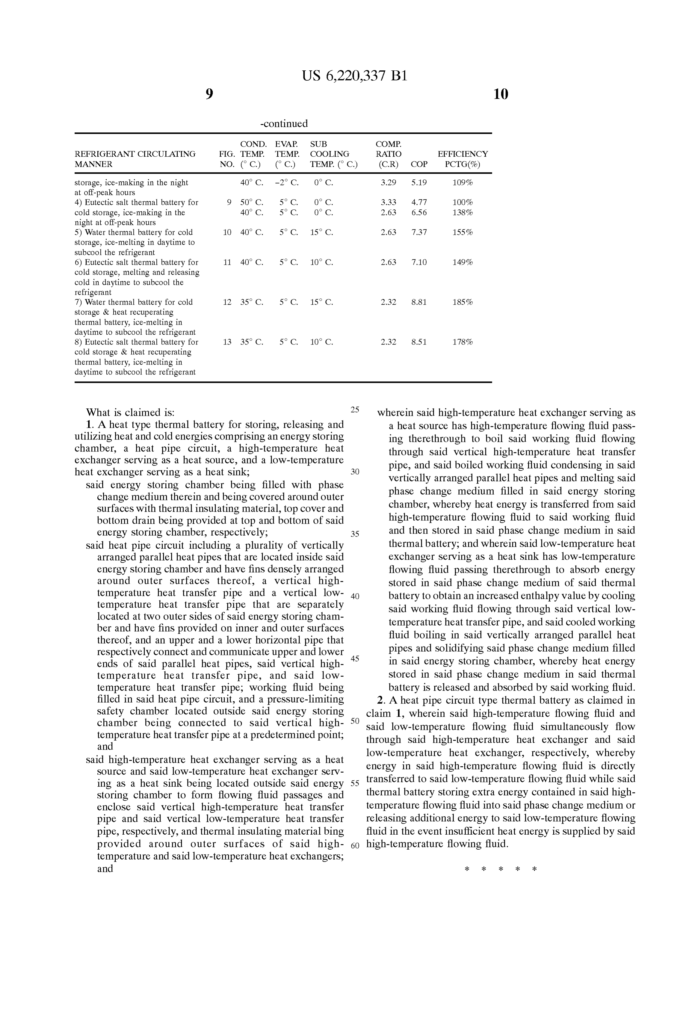
perature as that in the application shown in FIG. 10. Following is a table showing and comparing the coeffi However, the thermal battery 12 in this application uses cients of performance of different applications of the present eutectic Salt as its phase change medium and the Subcooling invention illustrated herein above:
REFRIGERANT CIRCULATING FIG. TEMP. TEMP COOLING RATIO EFFICIENCY MANNER NO. (C.) ( C.) TEMP. ( C.) (CR) COP PCTG (%) 1) Traditional air-cooled direct 6 50° C. 5° C. O C. 3.33 4.77 100% expansion air-conditioning system 2) Heat recuperating thermal battery 7 40° C. 5°C.. O C. 2.63 6.56 138%
3) Water thermal battery for cold 8 50° C. -2°C. O C. 4.17 3.90 82%
Page 21
REFRIGERANT CIRCULATING FIG. TEMP. TEMP COOLING RATIO EFFICIENCY MANNER NO. (C.) ( C.) TEMP. ( C.) (CR) COP PCTG(%) storage, ice-making in the night 40° C. -2° C. O. C. 3.29 S.19 O9% at off-peak hours 4) Eutectic salt thermal battery for 9 50° C. 5° C. O C. 3.33 4.77 OO% cold storage, ice-making in the 40° C. 5° C. O C. 2.63 6.56 38% night at off-peak hours 5) Water thermal battery for cold 1O 40° C. 5° C. 15°C 2.63 7.37 55% storage, ice-melting in daytime to subcool the refrigerant 6) Eutectic salt thermal battery for 11 40° C. 5° C. 10°C 2.63 7.10 49% cold storage, melting and releasing cold in daytime to subcool the refrigerant 7) Water thermal battery for cold 12 35° C. 5° C. 15° C. 2.32 8.81 85% storage & heat recuperating thermal battery, ice-melting in daytime to subcool the refrigerant 8) Eutectic salt thermal battery for 13 35° C. 5° C. 10° C. 2.32 8.51 78% cold storage & heat recuperating thermal battery, ice-melting in daytime to subcool the refrigerant
What is claimed is: 25 wherein Said high-temperature heat eXchanger Serving as 1. A heat type thermal battery for Storing, releasing and a heat Source has high-temperature flowing fluid pass utilizing heat and cold energies comprising an energy Storing ing therethrough to boil Said working fluid flowing chamber, a heat pipe circuit, a high-temperature heat through said vertical high-temperature heat transfer eXchanger Serving as a heat Source, and a low-temperature pipe, and Said boiled working fluid condensing in Said heat eXchanger Serving as a heat Sink, Vertically arranged parallel heat pipes and melting Said Said energy Storing chamber being filled with phase phase change medium filled in Said energy Storing change medium therein and being covered around outer chamber, whereby heat energy is transferred from Said Surfaces with thermal insulating material, top cover and high-temperature flowing fluid to Said working fluid bottom drain being provided at top and bottom of Said energy Storing chamber, respectively; 35 and then Stored in Said phase change medium in Said Said heat pipe circuit including a plurality of Vertically thermal battery; and wherein Said low-temperature heat arranged parallel heat pipes that are located inside Said eXchanger Serving as a heat Sink has low-temperature energy Storing chamber and have fins densely arranged flowing fluid passing therethrough to absorb energy around outer Surfaces thereof, a vertical high Stored in Said phase change medium of Said thermal temperature heat transfer pipe and a vertical low 40 battery to obtain an increased enthalpy value by cooling temperature heat transfer pipe that are Separately Said working fluid flowing through said vertical low located at two outer Sides of Said energy Storing cham temperature heat transfer pipe, and Said cooled working ber and have fins provided on inner and outer Surfaces fluid boiling in Said vertically arranged parallel heat thereof, and an upper and a lower horizontal pipe that pipes and Solidifying Said phase change medium filled respectively connect and communicate upper and lower 45 ends of Said parallel heat pipes, Said vertical high in Said energy Storing chamber, whereby heat energy temperature heat transfer pipe, and Said low Stored in Said phase change medium in Said thermal temperature heat transfer pipe, working fluid being battery is released and absorbed by said working fluid. filled in Said heat pipe circuit, and a preSSure-limiting 2. A heat pipe circuit type thermal battery as claimed in Safety chamber located outside Said energy Storing claim 1, wherein Said high-temperature flowing fluid and chamber being connected to Said vertical high 50 Said low-temperature flowing fluid Simultaneously flow temperature heat transfer pipe at a predetermined point, through Said high-temperature heat eXchanger and Said and
Said high-temperature heat eXchanger Serving as a heat low-temperature energy in Said heat eXchanger, respectively, whereby high-temperature flowing fluid is directly
Source and Said low-temperature heat eXchanger Serv ing as a heat Sink being located outside Said energy 55 transferred to said low-temperature flowing fluid while said Storing chamber to form flowing fluid passages and thermal battery Storing extra energy contained in Said high enclose Said vertical high-temperature heat transfer temperature flowing fluid into Said phase change medium or pipe and Said vertical low-temperature heat transfer releasing additional energy to Said low-temperature flowing pipe, respectively, and thermal insulating material bing fluid in the event insufficient heat energy is Supplied by Said provided around outer Surfaces of Said high 60 high-temperature flowing fluid.
temperature and Said low-temperature heat eXchangers, and
Provenance
- Collection
- Cited prior art
- Original PDF
- patentimages.storage.googleapis.com →
- Filed
- 1998-04-27
- Pages
- 21
- Method
- pdftotext (the PDF's own text layer) + pdftoppm 300dpi page scans
- Source
- Google Patents bibliographic record
- Granted
- 2001-04-24
- Inventors
- Shi-Li Chen; Ming-Jer Hsiao
- Transcribed from
- patentimages.storage.googleapis.com →