patent · US4117696
Heat pump
3 October 1978
Page 1 — bibliographic record
United States Patent (19) 11) 4,117,696 Fawcett et al. 45 Oct. 3, 1978
(54) HEAT PUMP unrestrained bodies. The bodies are accelerated around the passageway in one direction by isentropic expansion 75) Inventors: Sherwood L. Fawcett, Columbus; of a fluid between the bodies in an expander region of James N. Anno, Cincinnati, both of the passageway. The expanded, cooler fluid is dis Ohio charged from the passageway via one or more vent 73) Assignee: Battelle Development Corporation, intake ports in the passageway beyond the expander Columbus, Ohio region. Warmer fluid enters the passageway via said 21 Appl. No.: 812,559 ports and is compressed between the propelled bodies in a compression region of the passageway, thereby rais (22 Filed: Jul. 5, 1977 ing its temperature from a first temperature (e.g., the 51) Int. Cl. ......................... F25B 1/00; F25B 13/00; temperature of the outdoor atmosphere or an industrial F16D 31/00, FO1C 1/00 waste heat stream) to a second temperature higher than 52 U.S.C. ........................................ 62/115; 62/324; the first. The compressed, warmer fluid is thereafter 60/325; 418/33 passed through a heat exchanger to extract heat. In 58) Field of Search ................. 62/324, 401, 402, 115, passing through the compression region the bodies are 62/116; 60/325; 418/33; 290/1 R decelerated and they then pass through a thruster re (56) References Cited gion of the passageway wherein a force is applied to the
against the bodies as they move around the loop pas 3,859,789 1/1975 Fawcett et al. ........................ 60/325 sageway. From the thruster region the bodies pass to 3,927,329 12/1975 Fawcett et al. ........................ 418/33 the expander region to repeat the cycle. From the heat Primary Examiner-Lloyd L. King exchanger the fluid, typically together with additional Attorney, Agent, or Firm-Thomas H. Murray compressed fluid from an external source, is introduced
into the expander region to again accelerate the bodies.
Heat pump apparatus employing a continuous loop passageway containing a plurality of freely movable, 21 Claims, 5 Drawing Figures
COMMAAASSOAp
COAAAA
a/A Oly.
AAAMAAA
Page 2
Drawing sheet — no readable text.
Page 3
Drawing sheet — no readable text.
Page 4
Drawing sheet — no readable text.
Page 5
and passed through an optional, but preferred, check
HEAT PUMP valve and an optional, but preferred, latch, and then
BACKGROUND OF THE INVENTION
through heat exchanger means connected to the pas sageway at the end of the compression region for ex
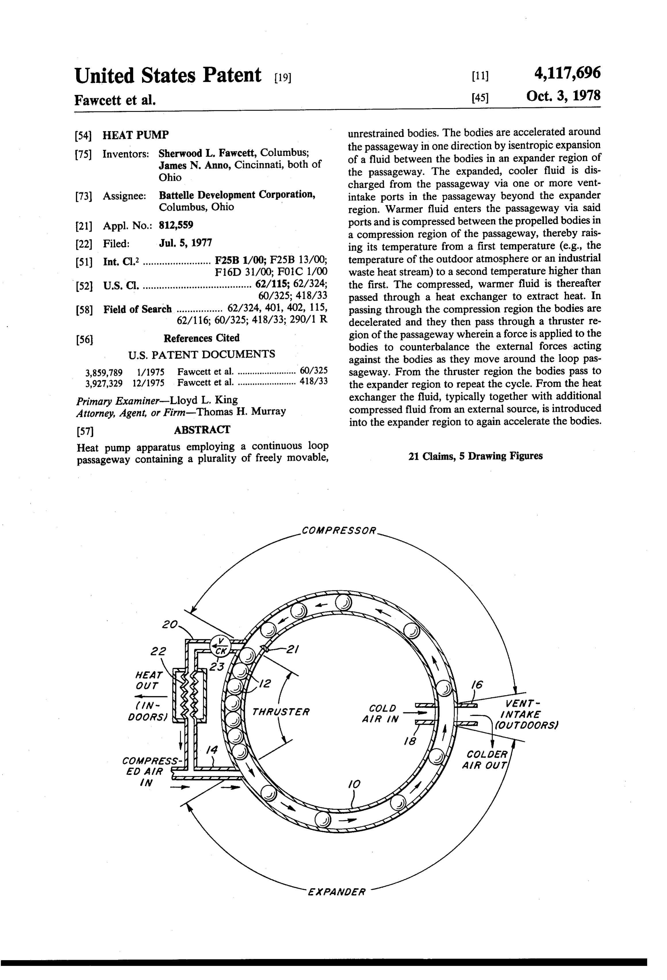
As is known, the usual heat pump used to heat build tracting heat from the fluid thus compressed. The ings, for example, includes an electrically driven com cooled compressed fluid is reintroduced into the pas pressor, a throttling valve, an evaporator located in the sageway together with an additional charge of com ambient atmosphere outside the building, and a con pressed fluid from the external compressor to repeat the denser within the building which discharges heat as a cycle, refrigerant is condensed. Such systems are relatively O The above and other objects and features of the in complicated, have low coefficients of performance vention will become apparent from the following de based upon actual thermal conversion and, of course, tailed description taken in connection with the accom require a liquid refrigerant which tends to be expensive panying drawings which form a part of this specifica and may have toxic properties. Furthermore, the en tion, and in which:
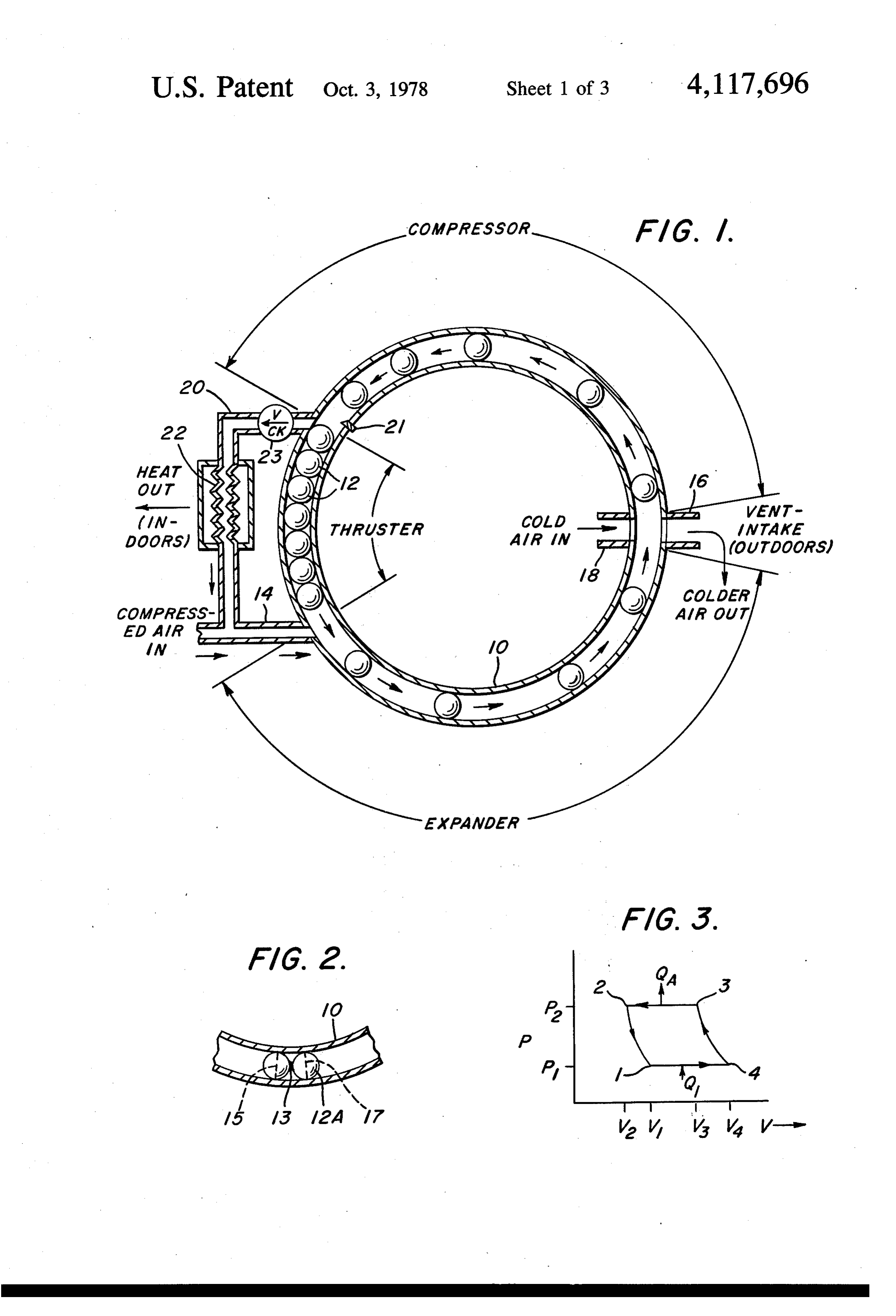
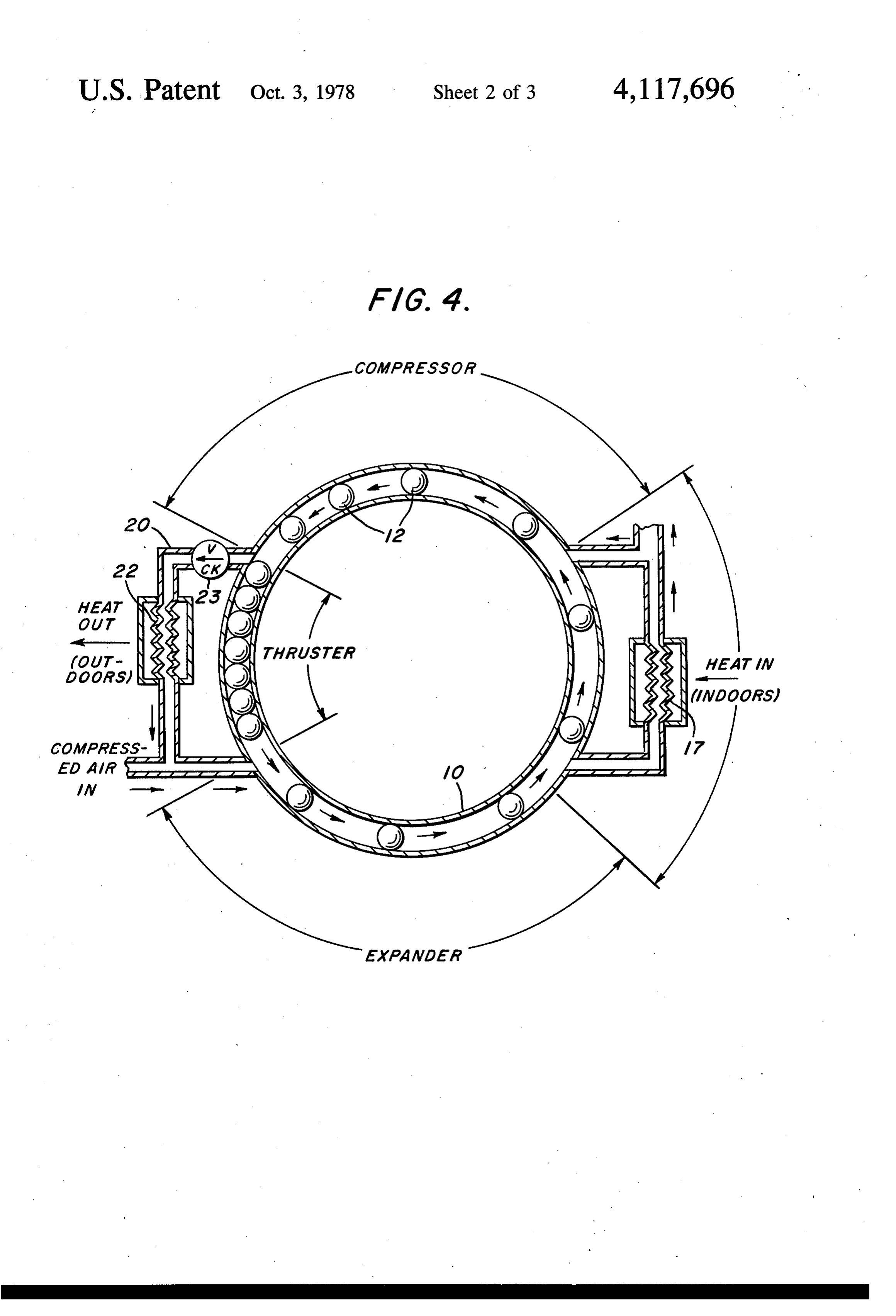
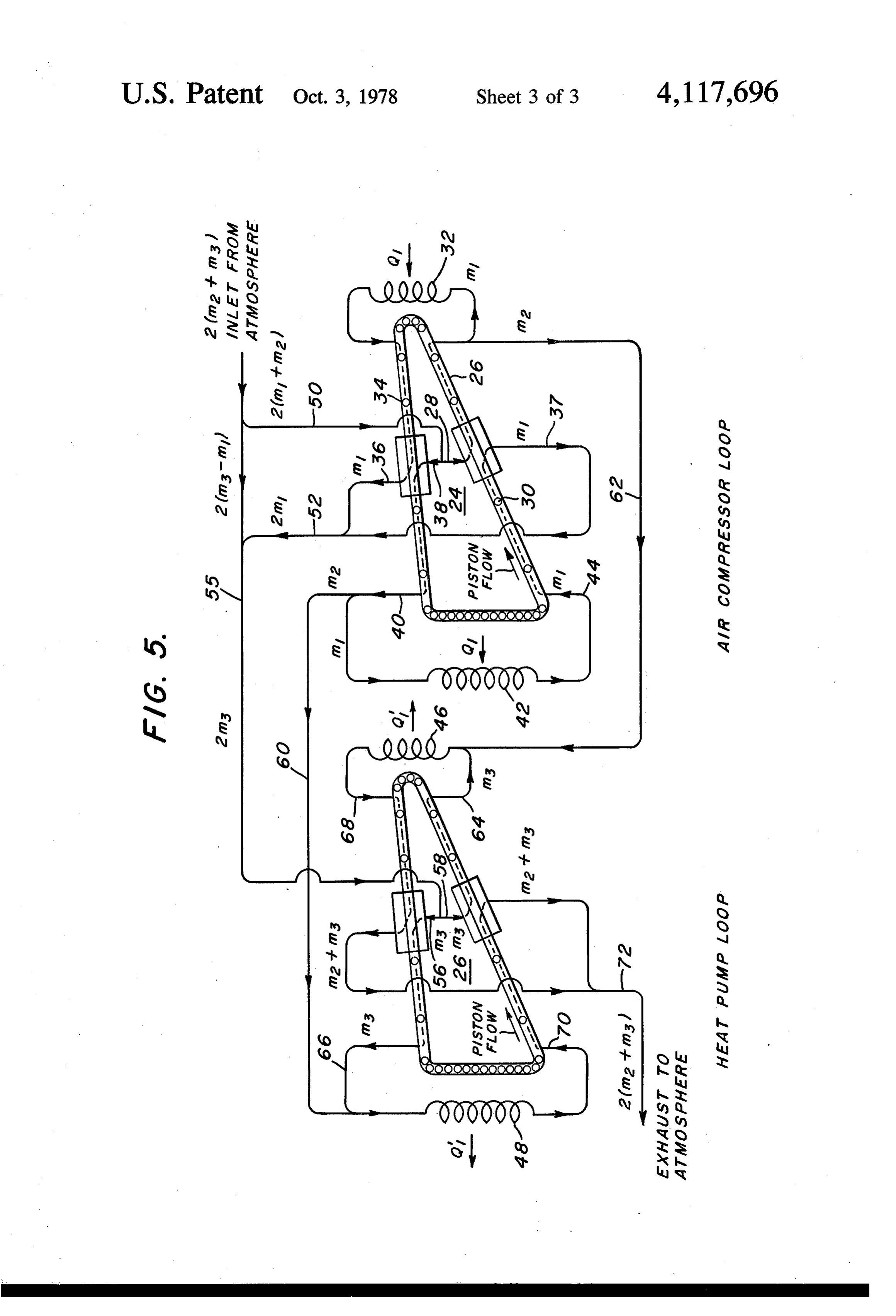
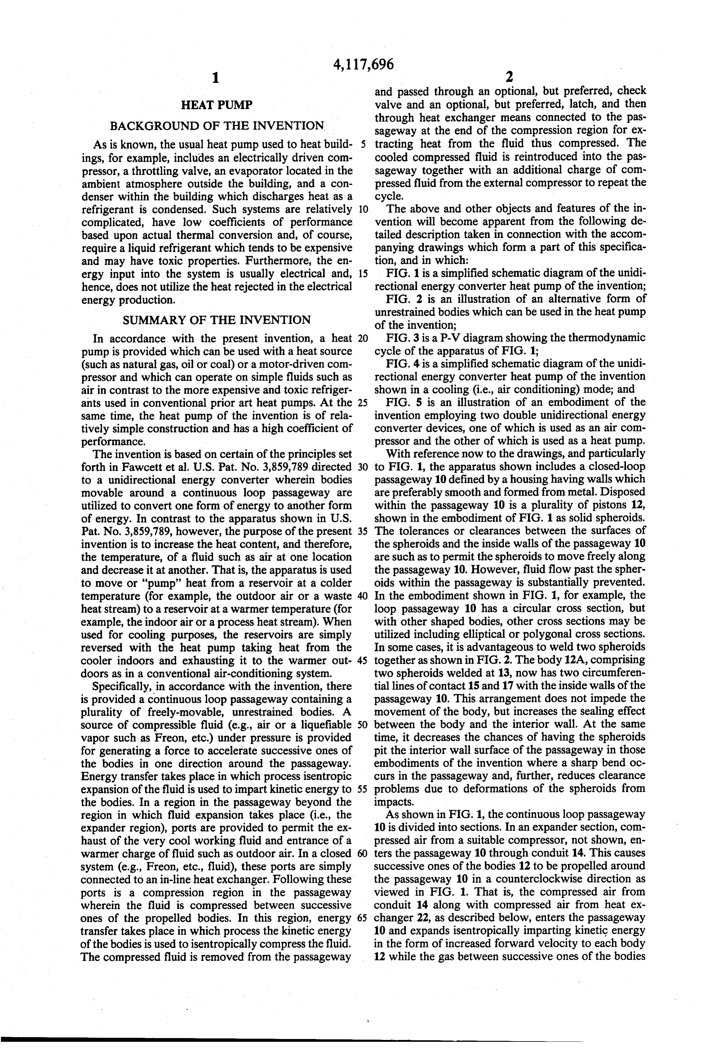
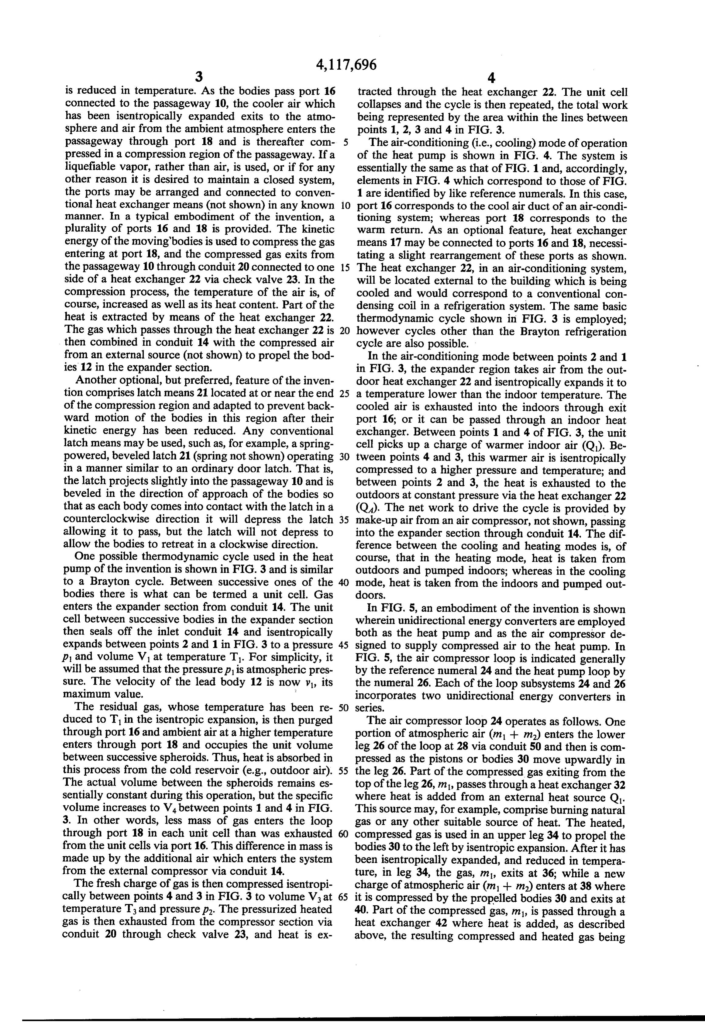
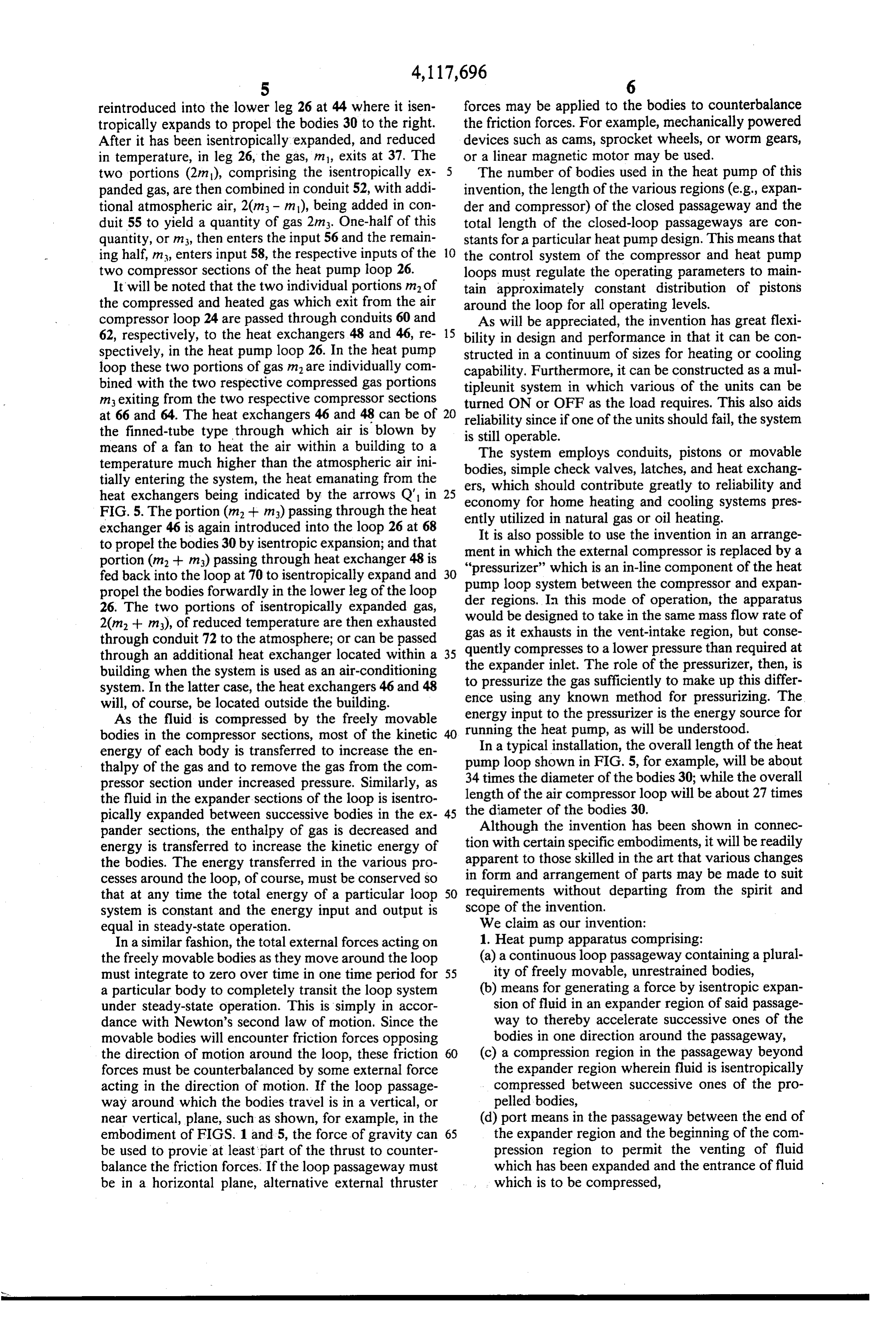
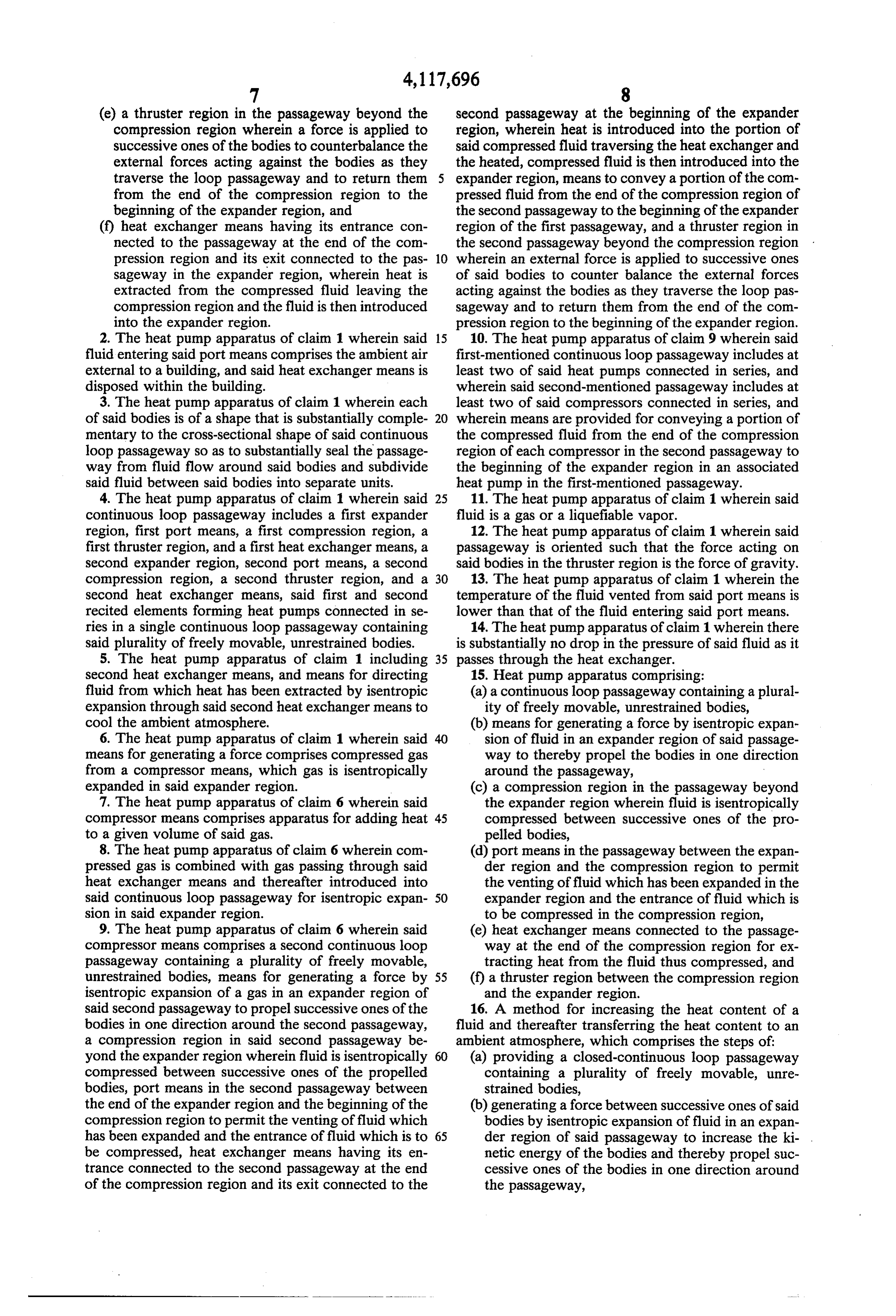
ergy input into the system is usually electrical and, 15 FIG. 1 is a simplified schematic diagram of the unidi hence, does not utilize the heat rejected in the electrical rectional energy converter heat pump of the invention; energy production. FIG. 2 is an illustration of an alternative form of SUMMARY OF THE INVENTION unrestrained bodies which can be used in the heat pump of the invention;
In accordance with the present invention, a heat 20 FIG. 3 is a P-V diagram showing the thermodynamic pump is provided which can be used with a heat source cycle of the apparatus of FIG. 1;
(such as natural gas, oil or coal) or a motor-driven com FIG. 4 is a simplified schematic diagram of the unidi pressor and which can operate on simple fluids such as rectional energy converter heat pump of the invention air in contrast to the more expensive and toxic refriger shown in a cooling (i.e., air conditioning) mode; and ants used in conventional prior art heat pumps. At the 25 FIG. 5 is an illustration of an embodiment of the same time, the heat pump of the invention is of rela invention employing two double unidirectional energy tively simple construction and has a high coefficient of converter devices, one of which is used as an air com performance. pressor and the other of which is used as a heat pump. The invention is based on certain of the principles set With reference now to the drawings, and particularly forth in Fawcett et al. U.S. Pat. No. 3,859,789 directed 30 to FIG. 1, the apparatus shown includes a closed-loop to a unidirectional energy converter wherein bodies passageway 10 defined by a housing having walls which movable around a continuous loop passageway are are preferably smooth and formed from metal. Disposed utilized to convert one form of energy to another form within the passageway 10 is a plurality of pistons 12, of energy. In contrast to the apparatus shown in U.S. shown in the embodiment of FIG. 1 as solid spheroids. Pat. No. 3,859,789, however, the purpose of the present 35 The tolerances or clearances between the surfaces of invention is to increase the heat content, and therefore, the spheroids and the inside walls of the passageway 10 the temperature, of a fluid such as air at one location are such as to permit the spheroids to move freely along and decrease it at another. That is, the apparatus is used the passageway 10. However, fluid flow past the spher to move or "pump' heat from a reservoir at a colder oids within the passageway is substantially prevented. temperature (for example, the outdoor air or a waste In the embodiment shown in FIG. 1, for example, the heat stream) to a reservoir at a warmer temperature (for loop passageway 10 has a circular cross section, but example, the indoor air or a process heat stream). When with other shaped bodies, other cross sections may be used for cooling purposes, the reservoirs are simply utilized including elliptical or polygonal cross sections. reversed with the heat pump taking heat from the In some cases, it is advantageous to weld two spheroids cooler indoors and exhausting it to the warmer out 45 together as shown in FIG. 2. The body 12A, comprising doors as in a conventional air-conditioning system. two spheroids welded at 13, now has two circumferen Specifically, in accordance with the invention, there tial lines of contact 15 and 17 with the inside walls of the is provided a continuous loop passageway containing a passageway 10. This arrangement does not impede the plurality of freely-movable, unrestrained bodies. A movement of the body, but increases the sealing effect source of compressible fluid (e.g., air or a liquefiable 50 between the body and the interior wall. At the same vapor such as Freon, etc.) under pressure is provided time, it decreases the chances of having the spheroids for generating a force to accelerate successive ones of pit the interior wall surface of the passageway in those the bodies in one direction around the passageway. embodiments of the invention where a sharp bend oc Energy transfer takes place in which process isentropic curs in the passageway and, further, reduces clearance expansion of the fluid is used to impart kinetic energy to 55 problems due to deformations of the spheroids from the bodies. In a region in the passageway beyond the impacts.
region in which fluid expansion takes place (i.e., the As shown in FIG. 1, the continuous loop passageway expander region), ports are provided to permit the ex 10 is divided into sections. In an expander section, com haust of the very cool working fluid and entrance of a pressed air from a suitable compressor, not shown, en warmer charge of fluid such as outdoor air. In a closed 60 ters the passageway 10 through conduit 14. This causes system (e.g., Freon, etc., fluid), these ports are simply successive ones of the bodies 12 to be propelled around connected to an in-line heat exchanger. Following these the passageway 10 in a counterclockwise direction as ports is a compression region in the passageway viewed in FIG. 1. That is, the compressed air from wherein the fluid is compressed between successive conduit 14 along with compressed air from heat ex ones of the propelled bodies. In this region, energy 65 changer 22, as described below, enters the passageway transfer takes place in which process the kinetic energy 10 and expands isentropically imparting kinetic energy of the bodies is used to isentropically compress the fluid. in the form of increased forward velocity to each body The compressed fluid is removed from the passageway 12 while the gas between successive ones of the bodies
Page 6
is reduced in temperature. As the bodies pass port 16 tracted through the heat exchanger 22. The unit cell connected to the passageway 10, the cooler air which collapses and the cycle is then repeated, the total work has been isentropically expanded exits to the atmo being represented by the area within the lines between sphere and air from the ambient atmosphere enters the points 1, 2, 3 and 4 in FIG. 3.
passageway through port 18 and is thereafter com The air-conditioning (i.e., cooling) mode of operation pressed in a compression region of the passageway. If a of the heat pump is shown in FIG. 4. The system is liquefiable vapor, rather than air, is used, or if for any essentially the same as that of FIG. 1 and, accordingly, other reason it is desired to maintain a closed system, elements in FIG. 4 which correspond to those of FIG. the ports may be arranged and connected to conven 1 are identified by like reference numerals. In this case, tional heat exchanger means (not shown) in any known 10 port 16 corresponds to the cool air duct of an air-condi manner. In a typical embodiment of the invention, a tioning system; whereas port 18 corresponds to the plurality of ports 16 and 18 is provided. The kinetic warm return. As an optional feature, heat exchanger energy of the moving bodies is used to compress the gas means 17 may be connected to ports 16 and 18, necessi entering at port 18, and the compressed gas exits from tating a slight rearrangement of these ports as shown. the passageway 10 through conduit 20 connected to one 15 The heat exchanger 22, in an air-conditioning system, side of a heat exchanger 22 via check valve 23. In the will be located external to the building which is being compression process, the temperature of the air is, of cooled and would correspond to a conventional con course, increased as well as its heat content. Part of the densing coil in a refrigeration system. The same basic heat is extracted by means of the heat exchanger 22. thermodynamic cycle shown in FIG. 3 is employed; The gas which passes through the heat exchanger 22 is 20 however cycles other than the Brayton refrigeration then combined in conduit 14 with the compressed air cycle are also possible.
from an external source (not shown) to propel the bod In the air-conditioning mode between points 2 and 1 ies 12 in the expander section. in FIG. 3, the expander region takes air from the out Another optional, but preferred, feature of the inven door heat exchanger 22 and isentropically expands it to tion comprises latch means 21 located at or near the end 25 a temperature lower than the indoor temperature. The of the compression region and adapted to prevent back cooled air is exhausted into the indoors through exit ward motion of the bodies in this region after their port 16; or it can be passed through an indoor heat kinetic energy has been reduced. Any conventional exchanger. Between points 1 and 4 of FIG. 3, the unit latch means may be used, such as, for example, a spring cell picks up a charge of warmer indoor air (Q). Be powered, beveled latch 21 (spring not shown) operating 30 tween points 4 and 3, this warmer air is isentropically in a manner similar to an ordinary door latch. That is, compressed to a higher pressure and temperature; and the latch projects slightly into the passageway 10 and is between points 2 and 3, the heat is exhausted to the beveled in the direction of approach of the bodies so outdoors at constant pressure via the heat exchanger 22 that as each body comes into contact with the latch in a (Q). The net work to drive the cycle is provided by counterclockwise direction it will depress the latch 35 make-up air from an air compressor, not shown, passing allowing it to pass, but the latch will not depress to into the expander section through conduit 14. The dif allow the bodies to retreat in a clockwise direction. ference between the cooling and heating modes is, of One possible thermodynamic cycle used in the heat course, that in the heating mode, heat is taken from pump of the invention is shown in FIG.3 and is similar outdoors and pumped indoors; whereas in the cooling to a Brayton cycle. Between successive ones of the mode, heat is taken from the indoors and pumped out bodies there is what can be termed a unit cell. Gas doors.
enters the expander section from conduit 14. The unit In FIG. 5, an embodiment of the invention is shown cell between successive bodies in the expander section wherein unidirectional energy converters are employed then seals off the inlet conduit 14 and isentropically both as the heat pump and as the air compressor de expands between points 2 and 1 in FIG. 3 to a pressure 45 signed to supply compressed air to the heat pump. In p and volume V at temperature T. For simplicity, it FIG. 5, the air compressor loop is indicated generally will be assumed that the pressure p is atmospheric pres by the reference numeral 24 and the heat pump loop by sure. The velocity of the lead body 12 is now y, its the numeral 26. Each of the loop subsystems 24 and 26 maximum value. incorporates two unidirectional energy converters in The residual gas, whose temperature has been re 50 SeeS.
duced to T in the isentropic expansion, is then purged The air compressor loop 24 operates as follows. One through port 16 and ambient air at a higher temperature portion of atmospheric air (ml -- m) enters the lower enters through port 18 and occupies the unit volume leg 26 of the loop at 28 via conduit 50 and then is com between successive spheroids. Thus, heat is absorbed in pressed as the pistons or bodies 30 move upwardly in this process from the cold reservoir (e.g., outdoor air). 55 the leg 26. Part of the compressed gas exiting from the The actual volume between the spheroids remains es top of the leg 26, m1, passes through a heat exchanger 32 sentially constant during this operation, but the specific where heat is added from an external heat source Q1. volume increases to V4 between points 1 and 4 in FIG. This source may, for example, comprise burning natural 3. In other words, less mass of gas enters the loop gas or any other suitable source of heat. The heated, through port 18 in each unit cell than was exhausted compressed gas is used in an upper leg 34 to propel the from the unit cells via port 16. This difference in mass is bodies 30 to the left by isentropic expansion. After it has made up by the additional air which enters the system been isentropically expanded, and reduced in tempera from the external compressor via conduit 14. ture, in leg 34, the gas, m, exits at 36; while a new The fresh charge of gas is then compressed isentropi charge of atmospheric air (ml -- m) enters at 38 where cally between points 4 and 3 in FIG. 3 to volume V at 65 it is compressed by the propelled bodies 30 and exits at temperature T and pressure p. The pressurized heated 40. Part of the compressed gas, m, is passed through a gas is then exhausted from the compressor section via heat exchanger 42 where heat is added, as described conduit 20 through check valve 23, and heat is ex above, the resulting compressed and heated gas being
Page 7
reintroduced into the lower leg 26 at 44 where it isen forces may be applied to the bodies to counterbalance tropically expands to propel the bodies 30 to the right. the friction forces. For example, mechanically powered After it has been isentropically expanded, and reduced devices such as cams, sprocket wheels, or worm gears, in temperature, in leg 26, the gas, m, exits at 37. The or a linear magnetic motor may be used. two portions (2m), comprising the isentropically ex The number of bodies used in the heat pump of this panded gas, are then combined in conduit 52, with addi invention, the length of the various regions (e.g., expan tional atmospheric air, 20m - m), being added in con der and compressor) of the closed passageway and the duit 55 to yield a quantity of gas 2m. One-half of this total length of the closed-loop passageways are con quantity, or m3, then enters the input 56 and the remain stants for a particular heat pump design. This means that ing half, m, enters input 58, the respective inputs of the 10 the control system of the compressor and heat pump two compressor sections of the heat pump loop 26. loops must regulate the operating parameters to main It will be noted that the two individual portions mof tain approximately constant distribution of pistons the compressed and heated gas which exit from the air around the loop for all operating levels. compressor loop 24 are passed through conduits 60 and As will be appreciated, the invention has great flexi 62, respectively, to the heat exchangers 48 and 46, re 15bility in design and performance in that it can be con spectively, in the heat pump loop 26. In the heat pump structed in a continuum of sizes for heating or cooling loop these two portions of gas mare individually com capability. Furthermore, it can be constructed as a mul bined with the two respective compressed gas portions tipleunit system in which various of the units can be m exiting from the two respective compressor sections turned ON or OFF as the load requires. This also aids at 66 and 64. The heat exchangers 46 and 48 can be of 20 reliability since if one of the units should fail, the system the finned-tube type through which air is blown by is still operable.
means of a fan to heat the air within a building to a The system employs conduits, pistons or movable temperature much higher than the atmospheric air ini bodies, simple check valves, latches, and heat exchang tially entering the system, the heat emanating from the ers, which heat exchangers being indicated by the arrows Q' in 25 economy forshould home contribute greatly to reliability and heating and cooling systems pres
FIG. 5. The portion (m. -- m) passing through the heat ently utilized in natural gas or oil heating. exchanger 46 is again introduced into the loop 26 at 68 to propel the bodies 30 by isentropic expansion; and that ment in which the external the
It is also possible to use invention in an arrange compressor is replaced by a portion (m2 + m3) passing through heat exchanger 48 is "pressurizer” which is an in-line component of the heat fed back into the loop at 70 to isentropically expand and 30 pump loop system between the compressor and expan propel the bodies forwardly in the lower leg of the loop der regions. In this mode of operation, the apparatus 26. The two portions of isentropically expanded gas, 20m2 + m3), of reduced temperature are then exhausted would be designed to take in the same mass flow rate of through conduit 72 to the atmosphere; or can be passed gas as it exhausts in the vent-intake region, but conse quently compresses to a lower pressure than required at through an additional heat exchanger located within a 35 the expander inlet. The role of the pressurizer, then, is building when the system is used as an air-conditioning to pressurize the gas sufficiently to make up this differ system. In the latter case, the heat exchangers 46 and 48 ence using any known method for pressurizing. The will, of course, be located outside the building.
As the fluid is compressed by the freely movable energy input to the pressurizer is the energy source for bodies in the compressor sections, most of the kinetic 40 running the heat pump, as will be understood. In a typical installation, the overall length of the heat energy of each body is transferred to increase the en thalpy of the gas and to remove the gas from the com pump loop shown in FIG. 5, for example, will be about pressor section under increased pressure. Similarly, as 34 times the diameter of the bodies 30; while the overall the fluid in the expander sections of the loop is isentro thelength of the air compressor loop will be about 27 times pically expanded between successive bodies in the ex 45 diameter of the bodies 30.
pander sections, the enthalpy of gas is decreased and Although the invention has been shown in connec energy is transferred to increase the kinetic energy of tion with certain specific embodiments, it will be readily the bodies. The energy transferred in the various pro apparent to those skilled in the art that various changes cesses around the loop, of course, must be conserved so in form and arrangement of parts may be made to suit that at any time the total energy of a particular loop 50 requirements without departing from the spirit and system is constant and the energy input and output is scope of the invention.
equal in steady-state operation. We claim as our invention:
In a similar fashion, the total external forces acting on 1. Heat pump apparatus comprising: the freely movable bodies as they move around the loop (a) a continuous loop passageway containing a plural must integrate to zero over time in one time period for 55 ity of freely movable, unrestrained bodies, a particular body to completely transit the loop system (b) means for generating a force by isentropic expan under steady-state operation. This is simply in accor sion of fluid in an expander region of said passage dance with Newton's second law of motion. Since the way to thereby accelerate successive ones of the movable bodies will encounter friction forces opposing bodies in one direction around the passageway, the direction of motion around the loop, these friction 60 (c) a compression region in the passageway beyond forces must be counterbalanced by some external force the expander region wherein fluid is isentropically acting in the direction of motion. If the loop passage compressed between successive ones of the pro way around which the bodies travel is in a vertical, or pelled bodies, near vertical, plane, such as shown, for example, in the (d) port means in the passageway between the end of embodiment of FIGS. 1 and 5, the force of gravity can 65 the expander region and the beginning of the com be used to provie at least part of the thrust to counter pression region to permit the venting of fluid balance the friction forces. If the loop passageway must which has been expanded and the entrance of fluid be in a horizontal plane, alternative external thruster which is to be compressed,
Page 8
(e) a thruster region in the passageway beyond the second passageway at the beginning of the expander compression region wherein a force is applied to region, wherein heat is introduced into the portion of successive ones of the bodies to counterbalance the said compressed fluid traversing the heat exchanger and external forces acting against the bodies as they the heated, compressed fluid is then introduced into the traverse the loop passageway and to return them expander region, means to convey a portion of the com from the end of the compression region to the pressed fluid from the end of the compression region of beginning of the expander region, and the second passageway to the beginning of the expander (f) heat exchanger means having its entrance con region of the first passageway, and a thruster region in nected to the passageway at the end of the com the second passageway beyond the compression region pression region and its exit connected to the pas 10 wherein an external force is applied to successive ones sageway in the expander region, wherein heat is of said bodies to counter balance the external forces extracted from the compressed fluid leaving the acting against the bodies as they traverse the loop pas compression region and the fluid is then introduced sageway and to return them from the end of the com into the expander region. pression region to the beginning of the expander region. 2. The heat pump apparatus of claim 1 wherein said 15 10. The heat pump apparatus of claim 9 wherein said fluid entering said port means comprises the ambient air first-mentioned continuous loop passageway includes at external to a building, and said heat exchanger means is least two of said heat pumps connected in series, and disposed within the building. wherein said second-mentioned passageway includes at 3. The heat pump apparatus of claim 1 wherein each least two of said compressors connected in series, and of said bodies is of a shape that is substantially comple 20 wherein means are provided for conveying a portion of mentary to the cross-sectional shape of said continuous the compressed fluid from the end of the compression loop passageway so as to substantially seal the passage region of each compressor in the second passageway to way from fluid flow around said bodies and subdivide the beginning of the expander region in an associated said fluid between said bodies into separate units. heat pump in the first-mentioned passageway. 4. The heat pump apparatus of claim 1 wherein said 25 11. The heat pump apparatus of claim 1 wherein said continuous loop passageway includes a first expander fluid is a gas or a liquefiable vapor. region, first port means, a first compression region, a 12. The heat pump apparatus of claim 1 wherein said first thruster region, and a first heat exchanger means, a passageway is oriented such that the force acting on second expander region, second port means, a second said bodies in the thruster region is the force of gravity. compression region, a second thruster region, and a 30 13. The heat pump apparatus of claim 1 wherein the second heat exchanger means, said first and second temperature of the fluid vented from said port means is recited elements forming heat pumps connected in se lower than that of the fluid entering said port means. ries in a single continuous loop passageway containing 14. The heat pump apparatus of claim 1 wherein there said plurality of freely movable, unrestrained bodies. is substantially no drop in the pressure of said fluid as it 5. The heat pump apparatus of claim 1 including 35 passes through the heat exchanger.
second heat exchanger means, and means for directing 15. Heat pump apparatus comprising: fluid from which heat has been extracted by isentropic (a) a continuous loop passageway containing a plural expansion through said second heat exchanger means to ity of freely movable, unrestrained bodies, cool the ambient atmosphere. (b) means for generating a force by isentropic expan 6. The heat pump apparatus of claim 1 wherein said sion of fluid in an expander region of said passage means for generating a force comprises compressed gas way to thereby propel the bodies in one direction from a compressor means, which gas is isentropically around the passageway, expanded in said expander region. (c) a compression region in the passageway beyond 7. The heat pump apparatus of claim 6 wherein said the expander region wherein fluid is isentropically compressor means comprises apparatus for adding heat 45 compressed between successive ones of the pro to a given volume of said gas. pelled bodies, 8. The heat pump apparatus of claim 6 wherein com (d) port means in the passageway between the expan pressed gas is combined with gas passing through said der region and the compression region to permit heat exchanger means and thereafter introduced into the venting of fluid which has been expanded in the said continuous loop passageway for isentropic expan 50 expander region and the entrance of fluid which is sion in said expander region. to be compressed in the compression region, 9. The heat pump apparatus of claim 6 wherein said (e) heat exchanger means connected to the passage compressor means comprises a second continuous loop way at the end of the compression region for ex passageway containing a plurality of freely movable, tracting heat from the fluid thus compressed, and unrestrained bodies, means for generating a force by 55 (f) a thruster region between the compression region isentropic expansion of a gas in an expander region of and the expander region. said second passageway to propel successive ones of the 16. A method for increasing the heat content of a bodies in one direction around the second passageway, fluid and thereafter transferring the heat content to an a compression region in said second passageway be ambient atmosphere, which comprises the steps of: yond the expander region wherein fluid is isentropically (a) providing a closed-continuous loop passageway compressed between successive ones of the propelled containing a plurality of freely movable, unre bodies, port means in the second passageway between strained bodies, the end of the expander region and the beginning of the (b) generating a force between successive ones of said compression region to permit the venting of fluid which bodies by isentropic expansion of fluid in an expan has been expanded and the entrance of fluid which is to 65 der region of said passageway to increase the ki be compressed, heat exchanger means having its en netic energy of the bodies and thereby propel suc trance connected to the second passageway at the end cessive ones of the bodies in one direction around of the compression region and its exit connected to the the passageway,
Page 9
(c) exiting said fluid after isentropic expansion thereof 18. The method of claim 17 including the step of from the interior of said passageway at a reduced adding additional compressed fluid to the fluid passing temperature, through said heat exchanger means prior to introducing the mixture thereof into said passageway for isentropic (d) introducing a fluid at a temperature higher than expansion thereof.
said reduced temperature into the interior of said 19. The method of claim 16 wherein steps (b), (c), (d) passageway and thereafter compressing said intro and (e) are repeated at least twice as said unrestrained duced fluid between successive ones of the bodies bodies move around said continuous loop passageway. propelled by isentropic expansion, and 20. The method of claim 16 wherein said fluid is air, (e) thereafter passing the compressed fluid through 10 and said air is passed through a heat exchanger means heat exchanger means connected to the passage the within a building and air is introduced and exited from way at the completion of compression of said fluid 1ng. continuous loop passageway exterior to the build for extracting heat from the fluid thus compressed. 21. The method of claim 16 wherein said fluid is air 17. The method of claim 16 including the step of 15 which is passed through heat exchanger means external passing the compressed fluid after passage through said to a building and air exits and is introduced into said heat exchanger means back into said passageway to continuous loop passageway within the interior of the propel successive ones of the bodies in one direction building. is around the passageway.
Provenance
- Collection
- Cited prior art
- Original PDF
- patentimages.storage.googleapis.com →
- Filed
- 1977-07-05
- Pages
- 9
- Method
- pdftotext (the PDF's own text layer) + pdftoppm 300dpi page scans
- Source
- Google Patents bibliographic record
- Granted
- 1978-10-03
- Inventors
- Sherwood L. Fawcett; James N. Anno; Battelle Development Corp
- Transcribed from
- patentimages.storage.googleapis.com →