patent · US3618579
Auxiliary fuel delivery system
9 November 1971
Page 1 — bibliographic record
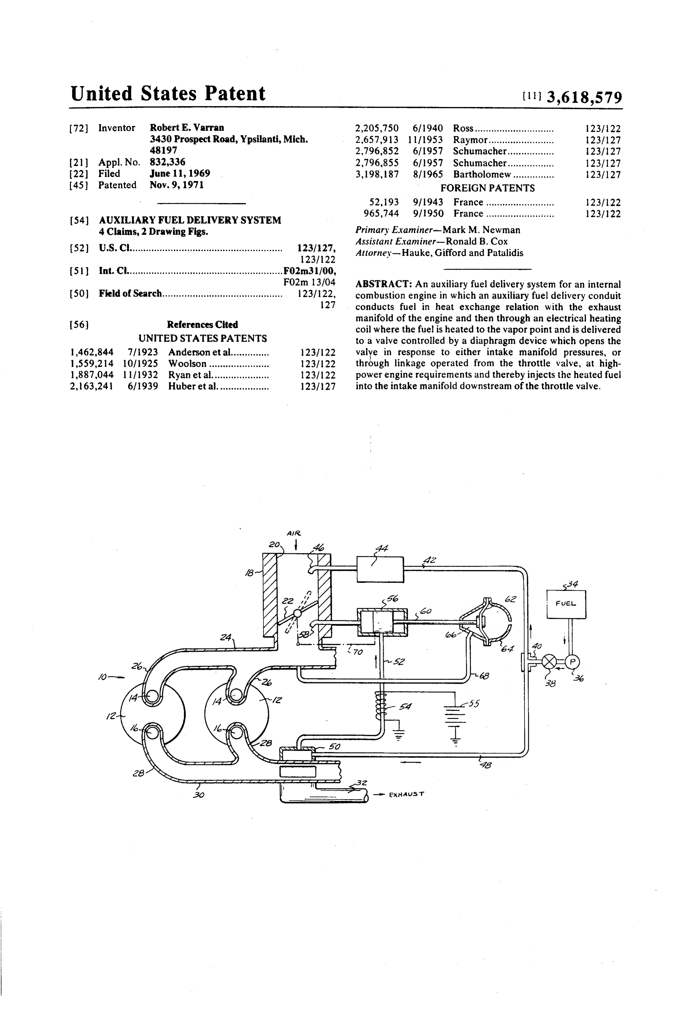
United States Patent (11) 3,618,579 (72) Inventor Robert E. Warran 2,205,750 61940 Ross............................. 1231122 3430 Prospect Road, Ypsilanti, Mich. 2,657,913 l 171953 Raymor.......... 123/127 48197 2,796,852 6f 1957 Schumacher................. 23/127 (21) Appl. No. 832,336 2,796,855 6, 1957 Schumacher................. 123/127 22 Filed June 11, 1969 3, 198,187 8/1965 Bartholomew............... 123/127 45) Patented Nov. 9, 1971 FOREIGN PATENTS 52, 93 9/1943 France......................... 23/22 965,744 9/1950 France ......................... 23/22
54 AUXLIARY FUEL DELIVERY SYSTEM
4 Claims, 2 Drawing Figs. Primary Examiner-Mark M. Newman
Assistant Examiner-Ronald B. Cox (52) U.S. Cl........................................................ 123/127, Attorney-Hauke, Gifford and Patalidis
(5) Int. Cl......................................................... F02m31/00,
FO2m 3/04 ABSTRACT: An auxiliary fuel delivery system for an internal 50 Field of Search............................................ 123/122, combustion engine in which an auxiliary fuel delivery conduit 127 conducts fuel in heat exchange relation with the exhaust 56 References Cited manifold of the engine and then through an electrical heating coil where the fuel is heated to the vapor point and is delivered
UNITED STATES PATENTS to a valve controlled by a diaphragm device which opens the 462,844 7/923 Anderson et al.............. 1231122 valye in response to either intake manifold pressures, or 1,559,214 101925 Woolson...................... 231122 through linkage operated from the throttle valve, at high 1,887,044 l l l 1932 Ryan et al..................... 1231122 power engine requirements and thereby injects the heated fuel 2, 63,241 6/1939 Huber et al................... 123/27 into the intake manifold downstream of the throttle valve.
air.
S Sess
Page 2
Drawing sheet — no readable text.
Page 3
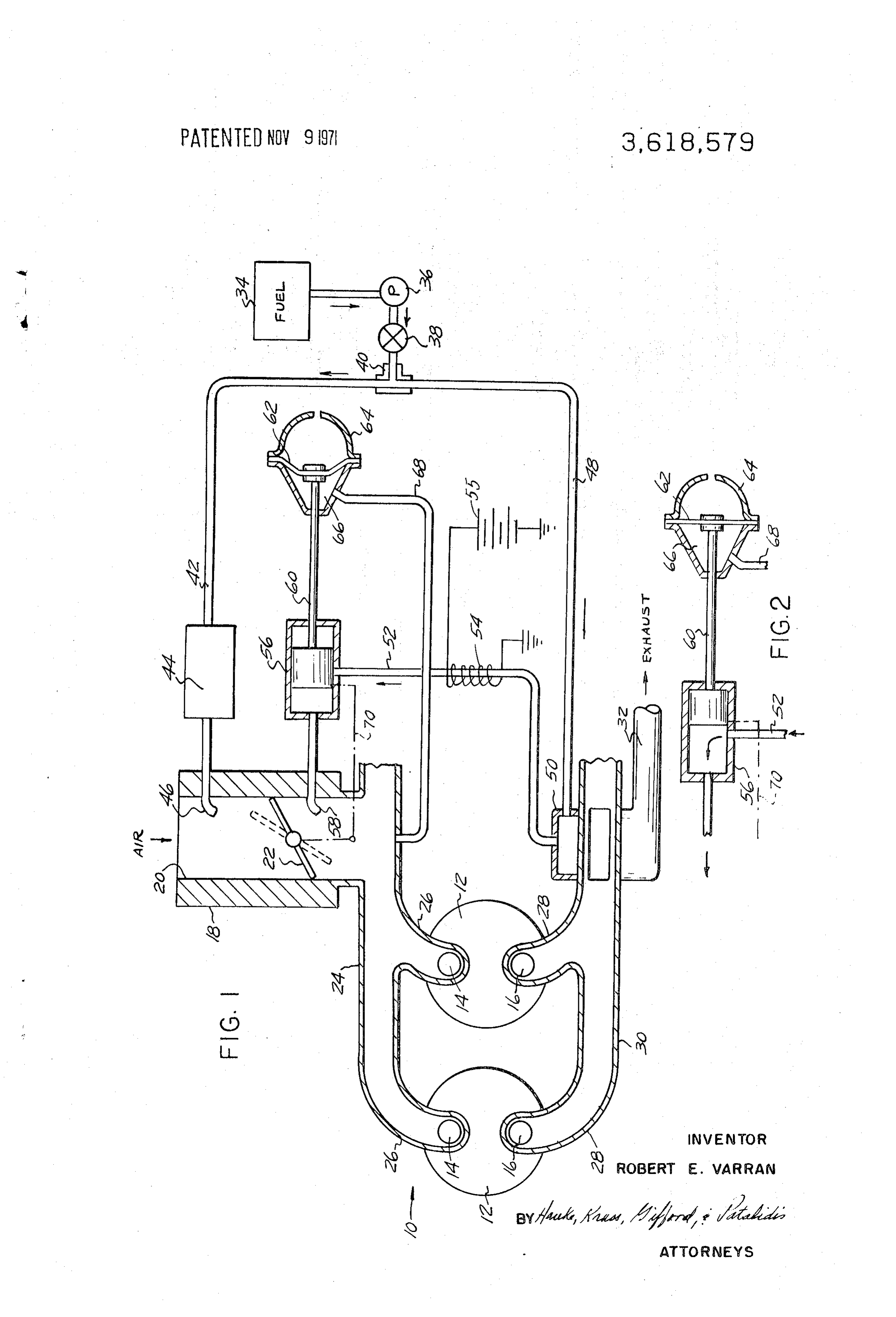
AUXLARY FUEL DELVERY SYSTEM tle valve 22 for variably delivery fuel-air mixture into an in take manifold 24 from which the mixture is delivered to the cylinder intake ports 14 through port runners 26.
BACKGROUND OF THE INVENTION Heated combustion products are exhausted from the cylin 1. Field of the Invention ders 12 through port runners 28 into an exhaust manifold 30 This invention relates to fuel-air mixture charging of inter from which they are discharged through an exhaust pipe 32. nal combustion engines in which an auxiliary fuel system sup The primary fuel system for the engine comprises a fuel plies heated fuel into the induction system in response to in tank 34 from which fuel is drawn by a pump 36 and delivered take manifold pressure changes or directly with opening of the O through a check valve 38 and a tee connection 40 or the like throttle valve. through a fuel delivery conduit 42, from whence the fuel is 2. Description of the Prior Art taken by a control device 44 of any preferred type and in Various prior patents illustrate the use of preheated fuel in jected into the carburetor 18 through a fuel port 46. The aux internal combustion engines. For example, U.S. Pat. No. iliary fuel supply system of the invention includes the fuel tank 2,719,520 discloses an electrically operated fuel vaporizer for 15 34, pump 36 and check valve 38 previously mentioned, from use in cold starting of an engine. U.S. Pat. No. 2,851,027 which fuel is diverted through the tee 40 into a conduit 48, shows a system for introducing electrically heated propane from which it flows into a heat chamber 50 disposed in heat into the intake manifold for cold starting of an engine. U.S. exchange relation to the exhaust manifold 30 as indicated. Pat. No. 2,974,656 relates to a fuel preheating device using Heated fuel is then conducted through a conduit 52 through a exhaust manifold heat to preheat all of the primary fuel heating coil 54 to a valve 56. The heating coil 54 is connected delivered to the carburetor. U.S. Pat. No. 3, l 10,296 discloses to a suitable electric power source 55 and operates to further a preheater and economizer for treating the fuel prior to en heat the fuel in the conduit 52 to at least its vapor point, so tering the carburetor using heated water therefore. U.S. Pat. that when the valve 56 opens the highly heated fuel vapor will No. 3,160,150 shows a choke-type system which is responsive be injected through an auxiliary fuel port 58 into the carbure to both temperature and manifold vacuum for cold starting. 25 tor 18 intermediate the throttle valve 22 and the intake U.S. Pat. No. 3,286,703 shows a system in which engine coo manifold 24.
lant preheats the fuel introduced into the carburetor float The valve 56 is operably connected by any means such as a bowl. control rod 60 with a diaphragm 62 mounted in a control I am not aware of any system in which an auxiliary supply of device 64 in such a manner as to form a variable volume con fuel diverted from the main fuel supply is preheated to a vapor 30 trol chamber 66. The control chamber 66 is openly connected point and introduced into the intake manifold in response to by means of a conduit 68 with the intake manifold 24. increases in manifold pressure experienced under certain In the position shown in FIG. 1, with the throttle valve 22 in high-power requirements of the engine or through a control the relatively closed or idle position of the engine, manifold linkage connected with the throttle valve. vacuum in the manifold 24 is relatively high, that is the 35 manifold pressure will be relatively low, and this pressure is sensed through the conduit 68 by the control device 64 so as
SUMMARY OF THE INVENTION to actuate the diaphragm 62 and its associated control rod 60 In the present invention, an auxiliary fuel delivery system to the left as shown to maintain the valve 56 in a closed posi for an internal combustion engine having an induction system 40 tion. At any time that the demands the engine are increased, including a carburetor with an air inlet and a throttle valve such as by an opening of the throttle valve 22 to the phantom variably admitting a fuel-air charge to the engine cylinders line position of FIG. 1, resulting in a loss of manifold vacuum, through an intake manifold, and in which there is a primary that is in an increase in manifold pressure to a degree per fuel system normally delivering fuel to the induction system mitting the diaphragm 62 to take the position indicated in for mixing with the air, the auxiliary fuel delivery system com 45 FIG. 2, the valve 56 will open to thereupon permit the highly prising a dual heating means, preferably an exhaust heater and heated fuel from the conduit 52 to be delivered from the out let 58 into the intake manifold 24.
an electrical heater, for heating a supply of fuel to the vapor point and delivering same independently of the primary fuel Alternatively, instead of a manifold pressure controller, a system to the induction system, with an intake manifold pres suitable linkage 70 indicated diagrammatically by a phantom sure responsive device or linkage to the throttle valve for 50 line, connects the throttle valve 22 and the valve 56 so that, selectively controlling a valve for delivering the heated fuel to under high power requirements, as the throttle valve opens to the induction system at selected operating ranges of the en a predetermined position, the valve 56 will open to permit the gine. highly heated fuel from the conduit 52 to be delivered from the outlet 58 into the intake manifold 24.
55 It will be apparent that many different types of control
DESCRIPTION OF THE DRAWINGS devices might be incorporated to achieve the desired result, For a more complete understanding of the invention, engine that is the addition of fuel which has a high heat content to the reference may be had to the accompanying drawing illustrat valves 56formight its immediate use therein. Also, various types of be used.
ing a preferred embodiment of the invention in which like 60 Although I have described and shown only one preferred reference characters refer to like parts throughout the several embodiment of my invention, it will be apparent to one skilled views and in which:
FIG. 1 is a diagrammatic illustration of an internal com and in the art to which the invention pertains that various changes bustion engine showing the fuel system embodying the present from modifications may be made therein without departing the spirit of the invention as expressed by the appended invention; and
FIG. 2 is a fragmentary diagrammatic view of a portion of 65 claims. claim:
the auxiliary fuel control in a delivery position. 1. An auxiliary fuel delivery system for an internal com bustion engine having an exhaust system, an induction system including a carburetor with an air inlet and a throttle valve
DESCRIPTION OF THE PREFERRED EMBODEMENTS 70 variably admitting a fuel-air charge to the engine cylinders As internal combustion engine 10 is illustrated diagram through an intake manifold, and a primary fuel system deliver matically as having engine cylinders 12 with intake ports 14 ing fuel from a fuel source to said induction system upstream and exhaust ports 16. of said throttle valve for mixing with air therein, said auxiliary The fuel-air induction system for the engine comprises a fuel delivery system comprising means heating a supply of the carburetor 18 having an air inlet 20 in which is located a throt 75 fuel taken from said same source and delivering same to said
Page 4
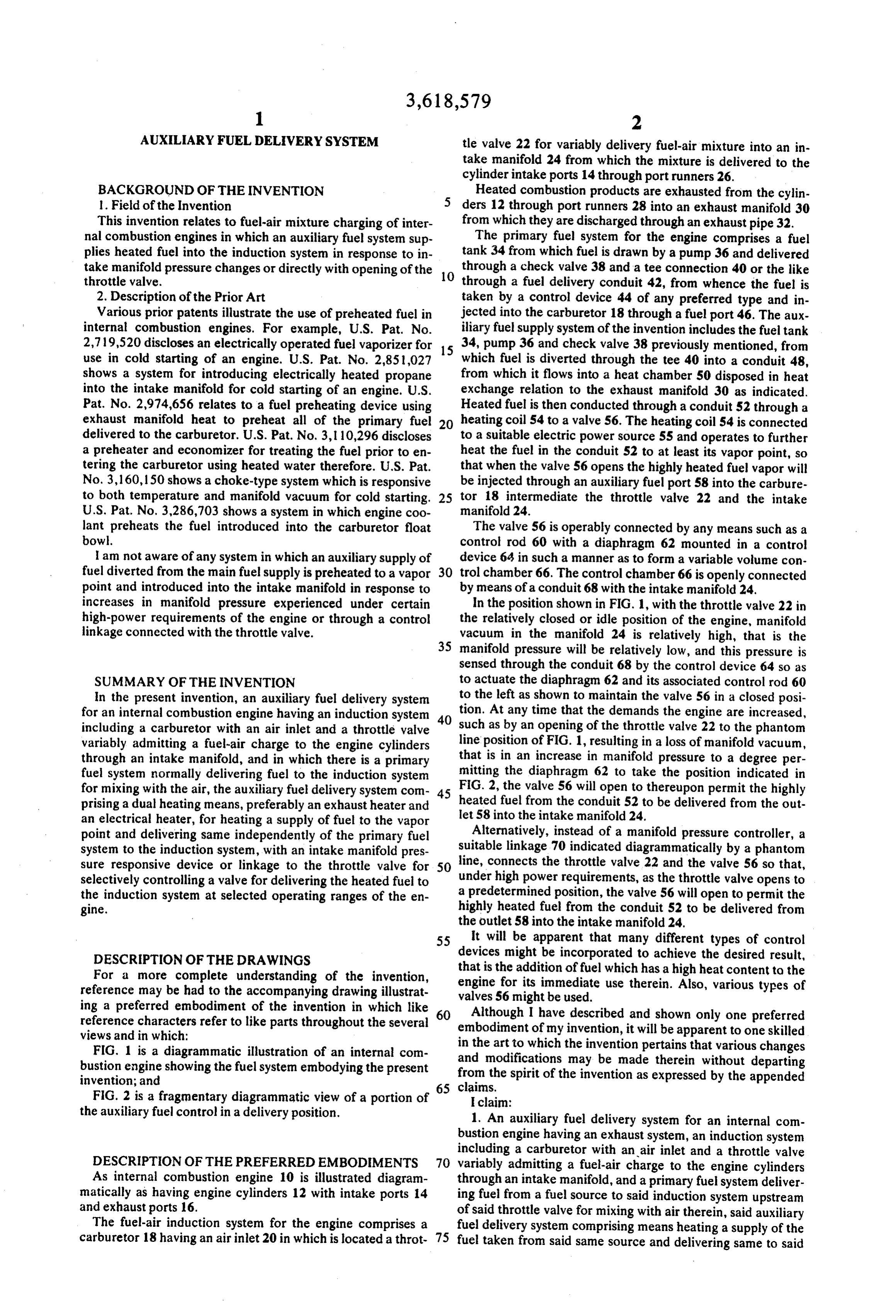
induction system downstream of said throttle valve and inde 2. The system as defined in claim 1 wherein said conduit has pendently of the delivery of fuel by said primary fuel system a valve intermediate said fuel heating means and the connec and means responsive to high power engine requirements for tion with said induction system, and control means responsive effecting delivery of said heated fuel upon a predetermined in to manifold pressure for selectively opening and closing said crease in manifold pressure, said fuel heating means heating 5 valve.
said fuel to the vapor point prior to delivery to said induction 3. The system as defined in claim 2 wherein said control system including a fuel conduit connected with said induction means comprises a housing having a variable volume system for delivering said heated fuel to said induction system, chamber, actuator means in said chamber operably connected said fuel heating means comprising an electric heating ele with said valve, and conduit means connecting said chamber ment adjacent said fuel conduit capable of heating the fuel in 10 with said induction system intermediate said throttle valve and the fuel conduit to the vapor point and a source of electric said engine cylinders to sense manifold pressure variations and power connected with said heating element, said heating alter said chamber volume respectively thereto, said actuator means further comprising said fuel conduit having a portion in means being operated upon altering of said chamber volume. heat exchange relationship with a portion of the exhaust 4. The system as defined in claim 1 wherein said conduit has system of said engine, said portion being disposed upstream of 15 a valve intermediate said heat source and the connection with said heating element whereby the fuel in said fuel conduit is said induction system, and mechanical control means preheated prior to delivery to said heating element, and said operably connecting said valve with said throttle valve for heating element acting in combination with said exhaust heat selectively opening and closing said valve. exchanger to further heat, if necessary, the auxiliary fuel to in sure heating to the vapor point temperature. s
Page 5
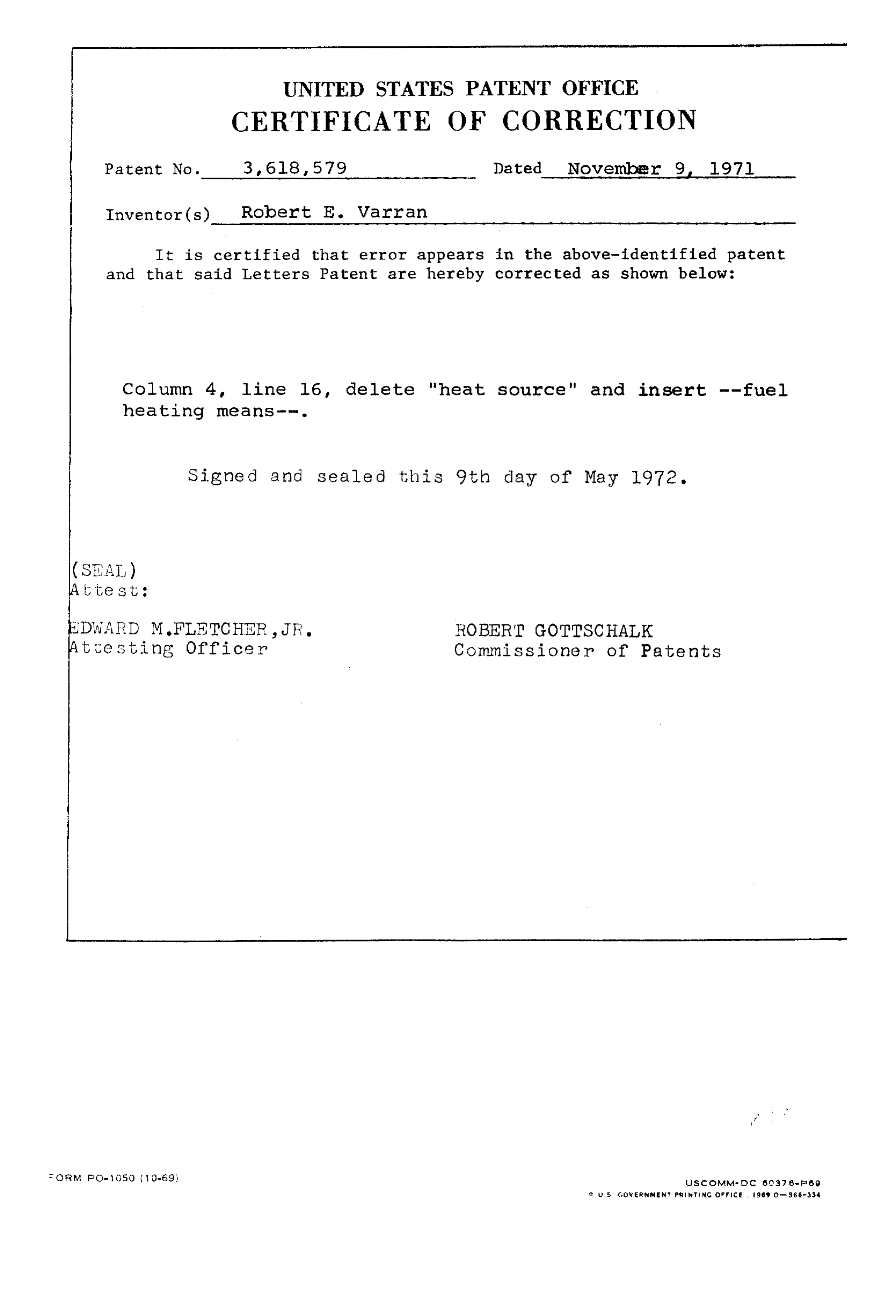
UNITED STATES PATENT OFFICE
CERTIFICATE OF CORRECTION
Patent No. 3, 68,579 Dated November 9, 1971 Inventor(s) Robert E. Varran
It is certified that error appears in the above-identified patent and that said Letters Patent are hereby corrected as shown below: Column 4, line l6, delete "heat source" and insert --fuel heating means--.
Signed and Sealed this 9th day of May 1972.
(SEAL)
test :
EDWARD M.FLETCHER, JR. ROBERT GOTTSCHALK
t testing Officer Commissioner of Patents FORM O-50 (1 O-69 us comma do so.37 sess U.S. GWERNME PRNTNs coffice 959 - 3 SS-334
Provenance
- Collection
- Cited prior art
- Original PDF
- patentimages.storage.googleapis.com →
- Filed
- 1969-06-11
- Pages
- 5
- Method
- pdftotext (the PDF's own text layer) + pdftoppm 300dpi page scans
- Source
- Google Patents bibliographic record
- Granted
- 1971-11-09
- Inventors
- Robert E Varran
- Transcribed from
- patentimages.storage.googleapis.com →