patent · US5994681
Apparatus for eddy current heating a body of graphite
30 November 1999
Page 1 — bibliographic record
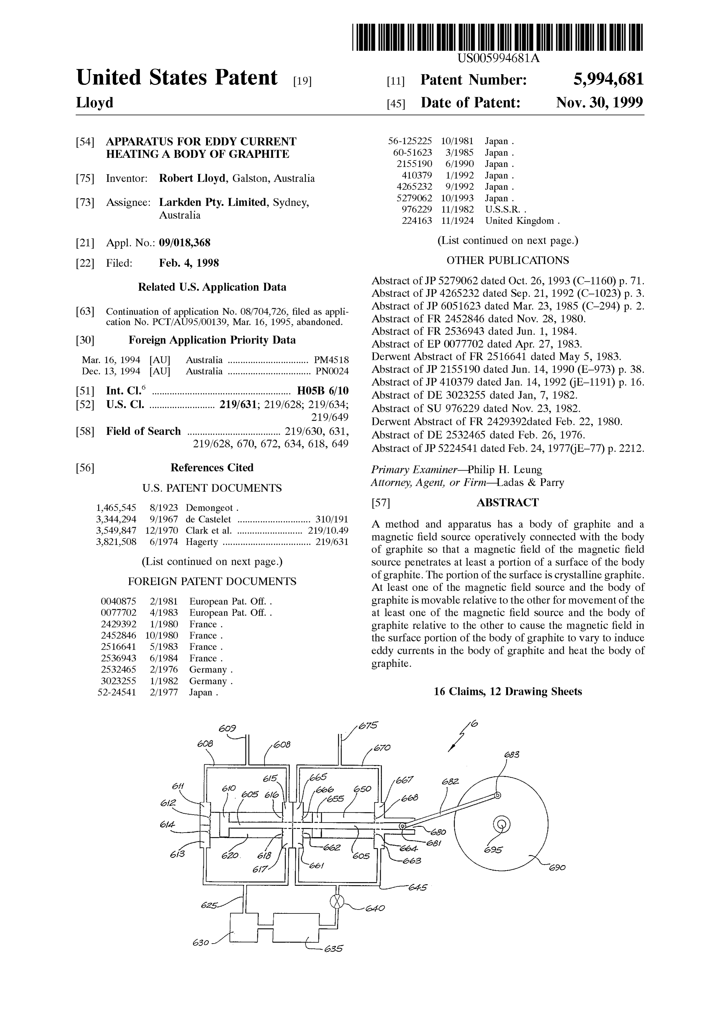
United States Patent (19) 11 Patent Number: 5,994,681 Lloyd (45) Date of Patent: Nov.30, 1999 54 APPARATUS FOR EDDY CURRENT 56-125225 10/1981 Japan . HEATING A BODY OF GRAPHITE 60-51623 3/1985 Japan .
75 Inventor: Robert Lloyd, Galston, Australia 410379 1/1992 Japan .
73 Assignee: Larkden Pty. Limited, Sydney, 5279062 10/1993 Japan .
Australia 224163 11/1924 United Kingdom.
21 Appl. No.: 09/018,368 (List continued on next page.) 22 Filed: Feb. 4, 1998 OTHER PUBLICATIONS
Related U.S. Application Data Abstract of JP 5279062 dated Oct. 26, 1993 (C-1160) p. 71.
63 Continuation of application No. 08/704,726, filed as appli Abstract of JP 6051623 dated Mar. 23, 1985 (C-294) p. 2. cation No. PCT/AU95/00139, Mar. 16, 1995, abandoned. Abstract of FR 2452846 dated Nov. 28, 1980.
30 Foreign Application Priority Data Abstract of EP 0077702 dated Apr. 27, 1983. Mar. 16, 1994 AU Australia ................................ PM4518 Derwent Abstract of FR 2516641 dated May 5, 1983. Dec. 13, 1994 AU Australia ................................. PNOO24 Abstract of JP 2155190 dated Jun. 14, 1990 (E-973) p. 38.
(51) Int. Cl. ................................................. H05B 6/10 Abstract of DE 3023255 dated Jan, 7, 1982. 52 U.S. Cl. .......................... 219/631; 219/628; 219/634; Abstract of SU 976229 dated Nov. 23, 1982. 219/649 Derwent Abstract of FR 2429392dated Feb. 22, 1980.
58 Field of Search ..................................... 219/630, 631, Abstract of DE 2532465 dated Feb. 26, 1976. 219/628, 670, 672, 634, 618, 649 Abstract of JP5224.541 dated Feb. 24, 1977GE-77) p. 2212. 56) References Cited Primary Examiner Philip H. Leung
1,465,545 8/1923 Demongeot. 57 ABSTRACT 3,344.294 9/1967 de Castelet ............................. 310/191 A method and apparatus has a body of graphite and a 3,549,847 12/1970 Clark et al. ... 219/10.49 magnetic field Source operatively connected with the body 3,821,508 6/1974 Hagerty ................................... 219/631 of graphite So that a magnetic field of the magnetic field
(List continued on next page.) Source penetrates at least a portion of a Surface of the body FOREIGN PATENT DOCUMENTS of graphite. The portion of the Surface is crystalline graphite. At least one of the magnetic field Source and the body of 0040875 2/1981 European Pat. Off.. graphite is movable relative to the other for movement of the 0077702 4/1983 European Pat. Off.. at least one of the magnetic field Source and the body of 2429392 1/1980 France. graphite relative to the other to cause the magnetic field in 2452846 10/1980 France. the Surface portion of the body of graphite to vary to induce 2516641 5/1983 France. eddy currents in the body of graphite and heat the body of 253,6943 6/1984 France. graphite.
52-24541 2/1977 Japan. 16 Claims, 12 Drawing Sheets
Page 2
4,678,881 7/1987 Griffith .................................... 219/631 3.942,026 3/1976 Carter ........................................ 290/55 4,089,176 5/1978 Ashe ... 219/628 4,139,677 2/1979 Blair et al. .. ... 428/409 FOREIGN PATENT DOCUMENTS 4,238.337 12/1980 Peters et al. ...... ... 219/628 4,291,235 9/1981 Bergey, Jr. et al. .. ... 290/55 1541221 2/1979 United Kingdom. 4,292,532 9/1981 Leroux ........... ... 290/6 2051.496 1/1981 United Kingdom. 4,299,205 11/1981 Garfield ......... 126/449 2088536 6/1982 United Kingdom. 4,358,306 11/1982 Okamoto et al. . ... 65/32 2149071 6/1985 United Kingdom. 4,421,967 12/1983 Birgel et al. ... ... 219/631 2207739 2/1989 United Kingdom. 4,486,638 12/1984 DeBennetot ... 219/631 2247 141 2/1992 United Kingdom. 4,511,777 4/1985 Gerard .................................... 219/631 2266.197 10/1993 United Kingdom.
Page 3
Drawing sheet — no readable text.
Page 4
Drawing sheet — no readable text.
Page 5
Drawing sheet — no readable text.
Page 6
Drawing sheet — no readable text.
Page 7
Drawing sheet — no readable text.
Page 8
Drawing sheet — no readable text.
Page 9
Drawing sheet — no readable text.
Page 10
Drawing sheet — no readable text.
Page 11
Drawing sheet — no readable text.
Page 12
Drawing sheet — no readable text.
Page 13
Drawing sheet — no readable text.
Page 14
Drawing sheet — no readable text.
Page 15
APPARATUS FOR EDDY CURRENT Further, known methods for the utilisation of Solar energy HEATING ABODY OF GRAPHITE in its various forms are Subject to inefficiencies, particularly, in the case of windmills or water turbines, at low air or water
This is a continuation of application Ser. No. 08/704,726 flow rates (Such as in low winds, in the case of windmills.) filed on Nov. 5, 1996 now abandoned which is PCT/AU95/ Thus there is a need for an improved apparatus for gener 00139 filed Mar. 16, 1995, claims the benefit thereof and ating electricity from a moving fluid, and for a an improved incorporates the same by reference. apparatus for more efficiently converting Solar energy in the form of wind or water power into more directly usable heat
The invention relates to a method and apparatus for Additionally, known methods for the collection of Solar collecting and/or Storing heat energy in a directly usable radiation using lenses or mirrors tend to be cumberSome and form. The invention also relates to a method for converting expensive Owing to the need for Sophisticated tracking heat energy into useful work and to an apparatus for use in equipment to permit the lens or mirror to be positioned at all Such a method. The invention further relates to an apparatus 15 times of the day and in all Seasons So as to collect the Sun's for generating electricity from a moving fluid. The invention rays. There is therefore a need for an improved process for Still further relates to a process for producing a lens. The producing a lens which can Simplify the collection of Solar invention even further relates to an apparatus and a method radiation.
for heating a body of material capable of being heated by OBJECTS OF THE INVENTION induced eddy currents. It is an object of the invention to provide an apparatus for BACKGROUND ART the collection and/or Storage of heat energy. It is a further There is a need for methods for the use, Storage or object of the invention to provide a method for the collection and/or Storage of heat energy. It is a Still further object of the recovery of forms of energy which at present are under invention to provide an apparatus for generating electricity utilised, or utilised inefficiently. Examples of Such forms of 25 from a moving fluid. It is yet a further object of the invention energy are waste heat from industrial processes, heat from provide an apparatus and a method for heating a body of waste incineration, and Solar energy in various forms, Such material capable of being heated by induced eddy currents. as insolation, tidal energy, wind energy, Ocean currents and hydrodynamic energy. Insolation energy conversion in par SUMMARY OF THE INVENTION ticular is the subject of intensive research. Present methods According to a first embodiment of the invention there is of collection of Solar energy mainly depend either on using provided an apparatus for the collection and Storage of heat the Solar collector to heat water and generate Steam which is energy, comprising:
then converted to rotary motive power, or on using Solar (a) a first body of graphite for the storage of heat energy, radiation to produce electrical energy in Solar cells. Other (b) means for heating the first body of graphite opera forms of waste heat energy are often utilised by heating tively associated with the first body of graphite to heat water and generating Steam. In Such processes, major losses 35 it, in the energy collection and conversion to Steam are inher (c) means for utilising the heat energy stored in the first ent. In addition, the energy collected and converted cannot body of graphite operatively associated with the first be economically Stored. Such a disadvantage is particularly acute in the collection of Solar energy, because of the 40 Thebody heat of graphite.
energy may be utilised directly, or after conver variability and unpredictability of the incidence of Solar Sion to another form of energy. Usually, the apparatus of the radiation.
invention further
The direct conversion of Solar energy to electricity is at in the first body of comprise means to convert the heat Stored graphite to usable power. Alternatively, present only possible with relatively low efficiencies. Cur the heat Stored in the first body of graphite may, for example, rent methods of Storing Solar energy converted into electrical 45 be used directly for Space heating or cooking. power are by use of electrical Storage batteries but in most Generally, the means for utilising the heat energy Stored cases, known batteries are too expensive and inefficient to in the first body of graphite comprises (d) means to heat a justify their widespread use. fluid, operatively associated with means to extract usable A further shortcoming of present energy Supply technolo power from the heated fluid.
gies results from the need for large Scale commercial pro 50 Usually, the means to heat a fluid comprises (e) one or ducers of electricity to install generating capacity Substan more further bodies of graphite for receiving heat from the tially in excess of the average demand, because electricity first body of graphite, (f) means operatively associated with generating plant must meet peaks of demand, which typi the bodies of graphite for transferring heat from the first cally occur in the mornings and evenings and which are body of graphite to the further bodies of graphite, and (g) usually highest in winter, and because there previously 55 means for contacting the fluid with the further body or existed no convenient and inexpensive method for Storing bodies of graphite, thereby heating the fluid. This form of the electrical energy on a large Scale. invention is usually used where the temperature of the first Thus, there is a need for a method which provides for body of graphite is too great for its efficient or practical use efficient conversion and/or Storage of energy, particularly directly to heat a fluid for the purpose of extracting uSable waste or low grade heat energy. 60 power therefrom, and enables a Suitable working tempera The unusual properties of graphite render it of Surprising ture to be attained for utilising the heat stored. Where utility in the collection and Storage of energy. The useful temperature considerations do not necessitate the use of properties of graphite in this connection include: (a) its high further bodies of graphite, the fluid to be heated may be thermal conductivity, (b) its high heat capacity, especially at contacted with the first body of graphite So as to heat the elevated temperatures and (c) heat lost by radiation is 65 fluid.
relatively low when graphite is hot (except for long wave The means for heating operatively associated with the first length radiation). body of graphite may comprise means for directing Solar
Page 16
energy onto the first body of graphite, for example using a are positioned adjacent a region of the Surface of the body mirror or lens to direct and focus light from the Sun onto the of the material capable of being heated by induced eddy Surface of the first body of graphite. Typically, means for currents, the assembly being rotated relative to the body of directing Solar energy onto the first mass of graphite may the material. More typically, the assembly of magnets is in comprise a lens. Usually, the lens is an elongated lens of the 5 the form of a circular plate, as described in more detail type described below. Alternatively, mirror or system of below. means
Generally, the assembly of magnetS is rotated by of a windmill or water-driven turbine. The material mirrors or other reflective surfaces may be used. Where the apparatus of the invention is used as a Solar energy collector, capable of being heated by induced eddy currents may be the Solar energy may be directed onto one or more exposed any electrically conductive, non-magnetic material. Surfaces of the first body of graphite. In that case, the first Generally, the material is graphite. Typically, the body of the body of graphite typically comprises an elongated projection material capable of being heated by induced eddy currents is onto which Solar energy is directed. the first body of graphite in an apparatus of the first Alternatively, the means for heating operatively associ embodiment of the invention.
ated with the first body of graphite may be electrical. AS a Still further alternative, the means for heating opera Electrical heating may be resistive or inductive. Typically, 15 tively associated with the first body of graphite may com electrical means for heating the first body of graphite prise means for contacting the first body of graphite with hot comprises an induction coil disposed to heat he first body of air or other gases containing waste or low grade heat. graphite when alternating current passes through the induc AS yet a further alternative, the first body of graphite may tion coil. Usually, the alternating current is applied from a be heated by the combustion of a fuel, for example coal or mains electricity Supply, for example using off-peak natural gas. In one form of this embodiment, the first body electricity, or is generated indirectly from Solar energy, for of graphite may be arranged in thermal communication with example from the wind or from the motion of water in a ceramic furnace adapted for the combustion of coal Streams or rivers or in the tides or ocean currents. admitted to the furnace. In this way, heat generated by the In another form of the present invention there is provided combustion may be stored in the body of graphite for later an apparatus for heating a body of material capable of being 25 use, or may be converted efficiently into rotary motive heated by induced eddy currents, comprising a magnetic power.
field Source, the magnetic field Source being operatively In a further form of the apparatus of the first embodiment, asSociated with the body of the material capable of being the means for heating comprises at least two means Selected heated by induced eddy currents So that the magnetic field of from the group consisting of means for directing Solar the magnetic field Source penetrates at least a portion of the energy onto the first body of graphite, electrical heating Surface of the body of material, at least one of the magnetic means, eddy current heating means, and means for combus field source and the body of material being movable relative ting a fuel.
to the other wherein movement of the magnetic field Source According to a Second embodiment of the invention there relative to the body of material causes the magnetic field in is provided a method for the collection, Storage and utilisa said surface portion of the body of material to vary, thereby 35 tion of heat energy, comprising:
inducing eddy currents in the body of material and heating (a) heating a first body of graphite for the collection of it. heat energy,
In this form of the invention the apparatus typically (b) storing the heat energy in the first body of graphite, further comprises means to move the magnetic field Source, and or the body of material capable of being heated by induced 40 (c) utilising the Stored heat from the first body of graphite. eddy currents, or both. Generally, the apparatus of this form The heat energy may be utilised directly as heat, or after of the invention further comprises heat insulation means conversion to another form of energy. Typically, the method operatively associated with the body of material capable of of the Second embodiment may comprise the Step of utilising being heated by induced eddy currents to reduce heat losses the heat stored in the first body of graphite as power. More therefrom. 45 typically, the Step of using the heat Stored in the first body There is also provided a method for heating a body of of graphite as power comprises the Steps of heating a fluid, material capable of being heated by induced eddy currents, and extracting uSable power from the fluid. comprising providing a body of material capable of being The Step of heating the fluid may comprise the Steps of heated by induced eddy currents and a magnetic field Source, transferring heat from the first body of graphite to one or at least one of the magnetic field Source and the body of 50 more further bodies of graphite and contacting the fluid with material being movable relative to one another, positioning the one or more further bodies of graphite, thereby heating the magnetic field Source So that its magnetic field penetrates the fluid. Alternatively, the fluid to be heated may be at least a portion of the Surface of the body of Said material, contacted directly with the first body of graphite. and moving at least one of the magnetic field Source and the Typically, in the apparatus of the first embodiment and the body of said material relative to the other sufficiently to 55 method of the Second embodiment, the uSable power is induce eddy currents in the body of said material and thereby motive power, more typically rotary motive power. heat the body of said material. Usually, in the apparatus of the first embodiment and the Typically, in the apparatus and method of this form of the method of the Second embodiment, the heated fluid is a gas, invention, the magnetic field Source is movable relative to typically air. However, other gases Such as nitrogen, argon, the body of material capable of being heated by induced 60 helium, carbon dioxide, Steam or mixtures thereof may be eddy currents, the body of material being fixed. More used. For the purpose of heating a fluid medium, a graphite typically, the means to move the magnetic field Source body which is to be used as the heat Store may comprise a comprises a windmill or a turbine driven by flowing water System of inter-connected hollowed chambers or tubes operatively associated with the magnetic field Source to through which the fluid medium can flow.
move it. 65 The graphite used in the method and apparatus of the Typically the magnetic field Source includes an assembly invention may be Synthetic or impure graphite or high of a plurality of permanent magnets or electromagnets which natural graphite. The graphite may contain mineral impuri
Page 17
S 6 ties. The use of high purity natural graphite is preferred, for along the length of which are projections or discs, arranged example graphite having a purity of from 95 weight % to Substantially perpendicularly to the direction of motion of 99.9 weight %, as higher storage heat levels are possible the cable. The cable is moved by motor-driven pulleys. when it is used, but graphite having a purity of 90-99 weight The differential temperature between any two graphite %, more typically from about 93 weight % to about 98 bodies between which heat is transferred may be controlled weight %, still more typically about 95 weight %, may be by the number, Size or material of the interconnecting heat used with excellent results. The graphite bodies may be transfer means. Alternatively, where a “Floveyer” or similar blocks of Solid graphite or compressed granular graphite. heat transfer means is utilised, the differential temperatures The graphite bodies may be fabricated from a single block may be controlled by the circulation rate of the conductive of graphite, or they may comprise two or more Smaller particles. Alternatively, the temperature of a body of graph blocks which are adapted to make efficient thermal contact ite from which heat is extracted may be controlled by with adjacent blocks when brought into contact with them. intermittently connecting and disconnecting the heat transfer In this embodiment, the smaller blocks may suitably be held means between that body of graphite and the graphite body in contact by passing graphite fibres around or through the which is used as the Source of heat. For example, the heat blocks and tensioning the graphite fibres. Alternatively, 15 transfer means may comprise a graphite block which may be crude graphite occurs naturally and is mined commercially. brought into contact with both graphite bodies Simulta Blocks of crude natural graphite as mined, typically about 90 neously. In this position, the hotter graphite body heats the weight % graphite, may, for example, be heated in vacuo to cooler one. When the cooler body reaches its desired about 2200–2500° C., more typically about 2400° C. until temperature, the heat transfer block may be separated from essentially no further volatiles are evolved, which typically one or both of the graphite bodies whereupon if Steps are provides graphite of at least about 95 weight% purity which taken to minimise convectional and radiant losses, little or may be used in the method and apparatus of the invention. no heat flows from one to the other. As heat is removed from AS a further alternatives, a body of graphite may be manu the cooler body and its temperature falls below a desired factured in Situ by forming a body of a Suitable carbonaceous level, the heat transfer block may be brought back into material and heating the carbonaceous material under 25 contact with the graphite bodies once again. One way of reduced pressure to graphitise the carbonaceous material. achieving the connection and disconnection of the heat Suitable carbonaceous materials for this purpose include transfer block is by disposing it in cooperation with a those materials of a relatively high carbon content which are bimetallic strip selected to deform sufficiently, at the desired Solid or Semi-Solid. Examples are amorphous carbon, tar, Set temperature of the cooler graphite body, to Separate the bitumen, pitch, asphalt, coal, anthracite and Sucrose. The heat transfer block from the graphite body or bodies. body of carbonaceous material may be reinforced with Typically, the graphite bodies and heat transfer means of carbon fibres or with carbon cloth. Thus, a typical method the apparatus and method of the invention are thermally for preparing a block of graphite for use as part of a graphite insulated from their Surroundings. Thermal insulation is body comprises the steps of (i) preparing a mixture of pitch, typically mineral fibre or ceramic. More typically, the SyS graphite cloth and graphite powder, (ii) Softening the mix 35 tem of graphite blocks and heat transfer means is Surrounded ture by heating it, (iii) charging the Softened mixture into a by a jacket or housing, which is evacuated internally to mould of the desired size and shape, (iv) positioning the minimise convectional heat loSS. The inner Surfaces of the charged mould in a heatable evacuatable enclosure, (v) jacket or housing are usually highly polished to minimise evacuating the enclosure to a pressure of 50 kPa or less, radiative heat loSS. Usually, the jacket or housing is a metal typically 10-50 kPa. (vi) heating the mould gradually to a 40 jacket. More usually, the jacket or housing is Steel. When the temperature of approximately 2200–2500 C., more typi jacket or housing is evacuated internally, the graphite body cally approximately 2400° C. for 24-48 hours while main or bodies is/are separated from the jacket or housing by one taining the pressure at 50 kPa or less, typically 10-50 kPa, or more insulating Spacers. The insulating Spacers may be a to graphitise the pitch, (vii) cooling the mould, (viii) admit Single thickness of ceramic, or two or more layers of the ting air to the enclosure and (ix) removing the graphitised 45 Same or different ceramics, optionally Separated by a layer of block from the mould. a metal, Such as Steel or aluminium. Examples of Suitable The heat transfer between the bodies of graphite, where ceramic thermal insulators include metal oxides Such as applicable, may be by one or more rods of conductive metal beryllium oxide, magnesium oxide, calcium oxide, Stron or graphite in contact with, or inserted or embedded in the tium oxide, osmium oxide, lanthanum trioxide, yttrium bodies of graphite, or by one or more blocks of conductive 50 trioxide, Scandium trioxide, titanium dioxide, Zirconium metal or graphite which are locatable in contact Simulta dioxide, hafnium dioxide, tantalum pentoxide, niobium neously with the bodies of graphite between which heat is to pentoxide, alumina, Silica, nickel oxide, and other inorganic be transferred, or by the use of a conveyor system for the materials. Such as Silicon nitride, Silicon carbide, boron transfer of loose granular conductive particles, or by any carbide, tantalum carbide, titanium carbide, tungsten combination of these methods. Suitable conductive metals 55 carbide, Zirconium carbide, aluminium nitride, Zirconium include high temperature Steel, aluminium, copper and Sil boride, Spinel, mullite, corundum, forsterite, fireclay, Ver. Granular conductive particles may be particles of a dolomite, Zircon, magnesite, high-alumina porcelains, high conductive metal or of graphite. Usually, the conductive magnesia porcelains, Sillimanite, kyanite, Zirconium Silicate particles are graphite. A Suitable conveyor System for the and mixtures thereof.
transfer of loose granular conductive particles is the 60 More typically, the insulating Spacers comprise one or “Floveyer” system manufactured by G.P.M. (Australia) Pty. more layers of graphite-impregnated ceramic in thermal Ltd. of North Strathfield, New South Wales. When used in contact with a heat eXchanger which Separates the impreg the apparatus of the first embodiment, the conveyor carries nated ceramic from the jacket or housing, as described in graphite particles in a circuit passing from one body of more detail below. In this arrangement, the heat eXchanger graphite into a another body of graphite and thereafter 65 can be maintained at a low enough temperature to minimise returning to the first-mentioned body of graphite. The trans heat loSS from the graphite body or bodies to the jacket or fer system of the Floveyer is drawn by a cable, at intervals housing while, with Suitable choice of graphite-impregnated
Page 18
ceramics, the body or body of graphite may be maintained transfer means from graphite, or by otherwise utilising at a very high temperature. Typically, the body or bodies of graphite in the heat transfer means as described above. graphite within the jacket or housing is/are maintained at a Where the first graphite body is heated electrically, this temperature of up to 2800 C. More typically, the body or may conveniently be achieved by arranging an induction bodies of graphite is/are maintained at a temperature of from coil Surrounding Some part of the graphite body and passing about 1400° C. to about 2000 C., even more typically at a an alternating current through the coil. Induced currents in temperature of about 1800 C. the graphite body then result in the graphite body being The housing may be evacuated internally and then Sealed heated. Typically, the frequency of the alternating current is So as to retain the internal vacuum, or it may be connected in the range of from 50 Hz to 100 MHz, more typically from to a vacuum pump for maintaining the vacuum. Typically, 50 Hz to 100 kHz, still more typically from 100 Hz to 10 where a vacuum pump is connected, the pump is arranged So kHz, even more typically about 960 Hz. as to operate only intermittently, for example when leaks The Source of electricity may be any convenient Source, cause the pressure in the housing to rise above a predeter Such as mains electricity, particularly where Supply at lower mined value. The vacuum in the housing is typically main priced rates is available at times of low electricity demand. tained in the range of from about 1 Pa to about 10 kPa, more 15 The energy Stored in the graphite bodies of the apparatus of typically on the range of from about 5 Pa to about 1 kPa, still the invention may then be used at times of peak electricity more typically in the range of from about 10 Pa to about 200 demand, resulting in cheaper overall electricity costs. A
It will be appreciated that direct contact between any of Similar to Smooth
Strategy can be used by electricity Suppliers in order the load demand on the electricity generators.
the bodies of graphite and hot air or other oxidising gases is to be avoided when the temperature of those gases is Such as remote locations, in
Alternatively,
many locations, and particularly in may be convenient for electrical energy to result in Substantial oxidation of the body or bodies of used to heat the first graphite graphite. The temperature at which Such oxidation occurs means associated with a movingbody fluid, to be generated by a
Such as flowing water depends on the purity of the graphite, but may be as low as in a stream or river, or ocean tides or 600 C. for impure graphitized carbon up to 930 C. for pure Designs for the generation of electricity currents, from Such or wind.
Sources natural graphite. 25
Where the temperature of one or more graphite bodies that the rotation speed of the turbine varies with the speed (i) of energy have hitherto Suffered from the disadvantages
exceeds the temperature at which oxidation occurs, an movement of the fluid and (ii) when fluids moving at low evacuated jacket as described above is usually employed.
Alternatively, the graphite bodies and/or heat transfer means Speeds impinge on known turbines insufficient torque is may be coated with a material Such as Ziron or oSmium oxide resistancesgenerated typically and the to overcome inertia in the generator, line like. In addition, maintenance costs are to prevent oxidation. high and storage Systems for the captured energy (typically The apparatus of the first embodiment and the method of batteries) are bulky, expensive the Second embodiment utilise the high thermal conductivity heating, by contrast, requires fewerandmoving inefficient. Inductive of graphite and its unusually high Specific heat at high ates by passing a high current at low voltages,parts, which and oper permits temperatures to provide a System for collection and Storage much more efficient use of the energy captured by a turbine.
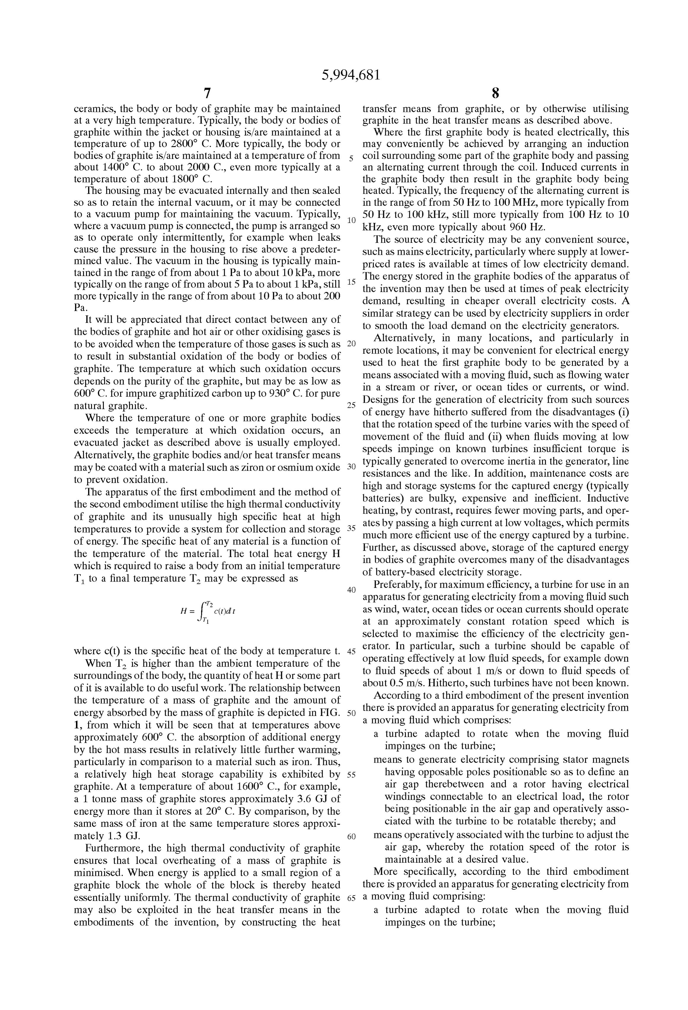
of energy. The Specific heat of any material is a function of Further, as discussed above, Storage of the captured energy the temperature of the material. The total heat energy H which is required to raise a body from an initial temperature in of bodies of graphite overcomes many of the disadvantages battery-based electricity Storage.
T to a final temperature T may be expressed as Preferably, for maximum efficiency, a turbine for use in an
apparatus for generating electricity from a moving fluid Such as wind, water, ocean tides or ocean currents should operate at an approximately constant rotation Speed which is
Selected to maximise the efficiency of the electricity gen where c(t) is the specific heat of the body at temperature t. 45 erator.
operating
In particular, Such a turbine should be capable of effectively at low fluid Speeds, for example down
When T is higher than the ambient temperature of the
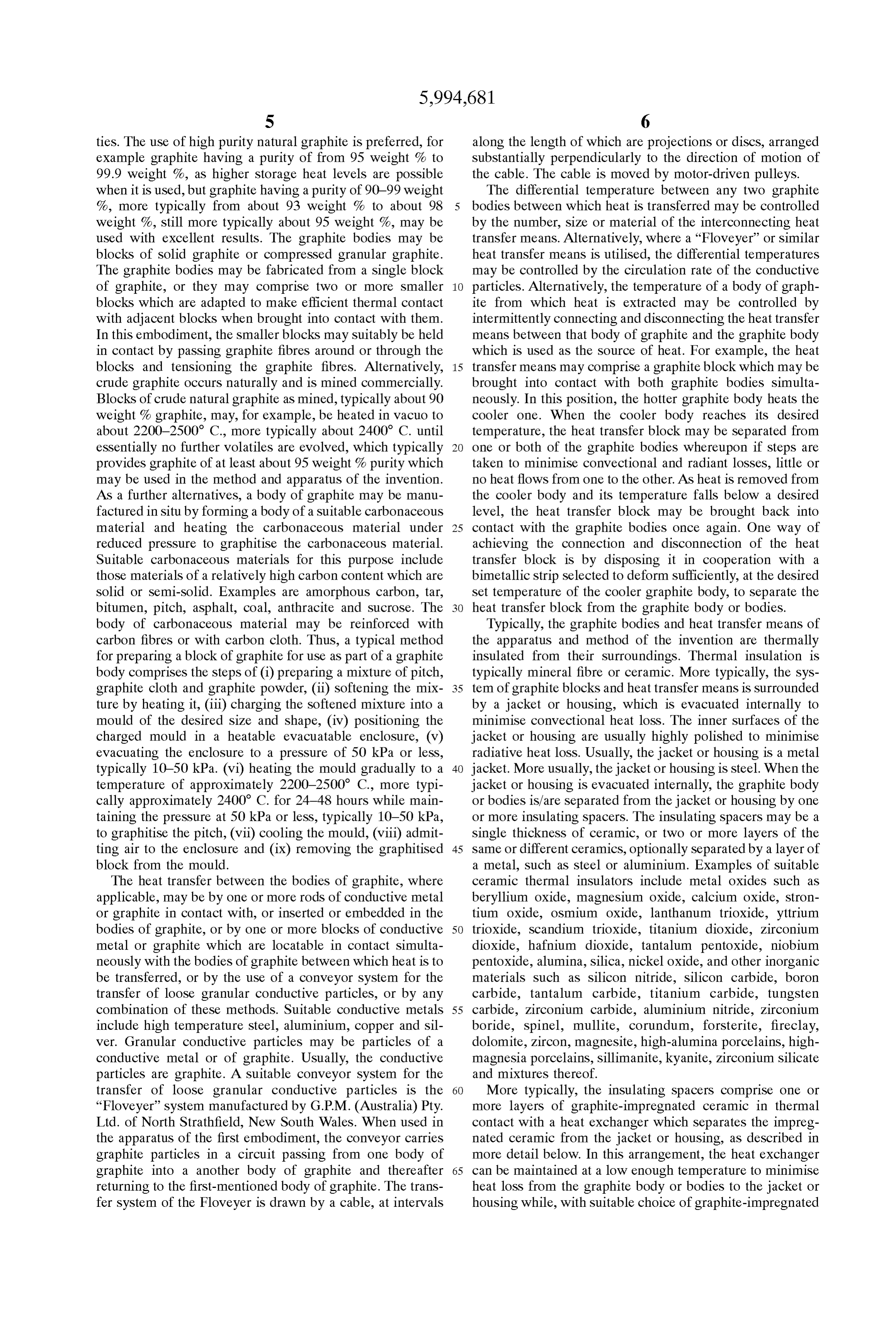
Surroundings of the body, the quantity of heat H or Some part to fluid speeds of about 1 m/s or down to fluid speeds of of it is available to do useful work. The relationship between about 0.5 m/s. Hitherto, Such turbines have not been known. According to a third embodiment of the present invention the temperature of a mass of graphite and the amount of there is provided an apparatus for generating electricity from energy absorbed by the mass of graphite is depicted in FIG. 50 a moving fluid which comprises: 1, from which it will be seen that at temperatures above approximately 600 C. the absorption of additional energy a turbine adapted to rotate when the moving fluid by the hot mass results in relatively little further warming, impinges on the turbine;
particularly in comparison to a material Such as iron. Thus, means to generate electricity comprising Stator magnets a relatively high heat Storage capability is exhibited by 55 having opposable poles positionable So as to define an graphite. At a temperature of about 1600 C., for example, air gap therebetween and a rotor having electrical a 1 tonne mass of graphite Stores approximately 3.6 GJ of windings connectable to an electrical load, the rotor energy more than it stores at 20° C. By comparison, by the being positionable in the air gap and operatively asso Same mass of iron at the same temperature Stores approxi ciated with the turbine to be rotatable thereby; and mately 1.3 G.J. 60 means operatively associated with the turbine to adjust the Furthermore, the high thermal conductivity of graphite air gap, whereby the rotation speed of the rotor is ensures that local overheating of a mass of graphite is maintainable at a desired value. minimised. When energy is applied to a Small region of a More Specifically, according to the third embodiment graphite block the whole of the block is thereby heated there is provided an apparatus for generating electricity from essentially uniformly. The thermal conductivity of graphite 65 a moving fluid comprising:
may also be exploited in the heat transfer means in the a turbine adapted to rotate when the moving fluid embodiments of the invention, by constructing the heat impinges on the turbine;
Page 19
means to generate electricity comprising at least one pair a plunger comprising an electrical contact region and a of Stator magnets and a rotor positioned in an air gap slider region, the electrical contact region comprising and operatively associated with the turbine to be rotat (i) positive and negative d.c. contacts connectable to able thereby, wherein the rotor has electrical windings the electrical windings of the rotor, and (ii) a first and connectable to an electrical load and wherein the air 5 Second pair of a.c. terminals of opposite polarity con gap is defined by the opposite poles of the magnets of nectable in parallel to an electrical load; the pairs positioned on opposite sides of the air gap; and wherein the Slider region is adapted to be maintainable in means operatively associated with the turbine and the sliding contact with the undulations of the disc or ring Stator magnets to move the magnets and thereby change and wherein the positive and negative d.c. contacts are the air gap, whereby the rotation speed of the rotor is in contact with the first pair of a.c. terminals at one Substantially maintainable at a desired value when the extreme of movement of the plunger in contact with the rotation Speed of Said turbine exceeds a predetermined undulations and the positive and negative d.c. contacts value.
The apparatus of the third embodiment may be adapted to are in contact with the Second pair of a.c. terminals at generate d.c. or a.c. Where the apparatus is adapted to 15 the other eXtreme of movement of the plunger in generate a.c., it will be appreciated that Since the rotation contact with the undulations. Speed of the rotor is maintained at a desired value, the Alternating current generated by the apparatus of the third frequency of the a.c. will be Substantially constant. Since the embodiment may be utilised for induction heating of a body rotor is driven by the turbine, a braking action on the rotor of graphite in an apparatus of the first embodiment. which results from a narrowing of the air gap between the Alternatively, as previously noted, mains electricity of 50 or magnets and the rotor results in a braking action on the 60Hz frequency may be utilised for induction heating of a turbine also. Typically, the apparatus of the third embodi body of graphite in an apparatus of the first embodiment. ment is adapted So that the rotation Speed of the turbine is Where high frequency induction heating is used, for maintainable at about 10-200 revolutions per minute, more example at a frequency in the range from about 100 Hz to typically about 30-100 revolutions per minute, even more about 100MHz as described above, this may be achieved by typically about 40-70 revolutions per minute, still more 25 methods generally known in the art. For example a spiral typically about 50 revolutions per minute. When the turbine arrangement of copper tubes may be passed around or is operated as a windmill, for example, it typically maintains through a part of the graphite body, and the high frequency a rotation Speed of about 50 revolutions per minute at a wind alternating current passed through these copper tubes. Speed of as low as 0.5 m/sec. Where insufficient cooling is provided by the graphite body The apparatus of the third embodiment may further com to prevent damage to or melting of the copper tubes, cooling prise means to convert d.c. to a.c. Suitably, the means to water may be passed through them. Typically, this method of convert d.c. to a.c. may be adapted to convert d.c. to any heating requires the use of cooling water in the copper tubes, Selected a.c. frequency, for example up to 250 kHz, or up to and the heat carried away by the water reduces the overall 100 kHz or up to 50 kHz. More typically, the means to efficiency of the induction heating System. In an alternative convert d.c. to a.c. is adapted to convert d.c. to a.c. of up to 35 System of induction heating, graphite fibres or graphite tape 5000 Hz, most typically of up to 1000 Hz. The means to may be passed around or through a part of a graphite body convert d.c. to a.c. may be electronic or mechanical. Elec in the apparatus of the first embodiment and Separated from tronic methods may utilise circuitry well known in the art for the graphite body by electrical insulation. The passage of the purpose. An example of a Suitable mechanical apparatus alternating current through the graphite fibres or graphite for converting d.c. to a.c. comprises means whereby d.c. 40 tape then causes inductive heating of the graphite body. generated by the apparatus of the third embodiment is Because of the high melting temperature of graphite, this connected alternately to one of two poles of an a.c. Supply, method of heating has the advantage that no coolant is the means being adapted to operate when the turbine rotates. required and consequently the heating of the graphite body Where the turbine rotation speed is relatively slow, the is more efficient. Where the thickness of the graphite body apparatus for converting d.c. to a.c. can comprise means for 45 is Sufficient, for example greater than about 150 mm, effi increasing the a.c. frequency. Suitably, Such an apparatus cient induction heating may be achieved using mains elec comprises: a disc or ring comprising a plurality of radially tricity or other electricity Supply at a frequency in the range Spaced undulations and adapted to rotate when the turbine of about 50-20000 Hz, more typically in the range of about rotates, a plunger comprising a fixed portion and a movable 50-5000 Hz, even typically in the range of about 50–1000 portion having a contact region, the contact region compris 50 Hz, still more typically in the range of about 50-100 Hz. ing positive and negative d.c. contacts connectable to the In the form of the invention in which the first body of electrical windings of the rotor; and a first and Second pair graphite is heated by eddy currents induced by moving a of a.c. terminals of reverse polarity connected in parallel; magnetic field Source relative to the first body of graphite, wherein the movable portion of the plunger is adapted to be essentially any movement of a magnetic field which pen maintainable in Sliding contact with the undulations of the 55 etrates a part of the first body of graphite will induce disc or ring and wherein movement of the moveable portion electrical currents in the graphite, owing to its electrical in contact with the undulations causes the positive and conductivity. The induced electrical currents flowing in the negative terminals to be alternately in contact with the first graphite produce a temperature rise in the graphite. Thus pair of a.c. terminals and the Second pair of a.c. terminals. heating may be caused, for example, by Sweeping a mag More particularly, the apparatus to convert d.c. to a.c. 60 netic field along one dimension of the graphite body and comprises: back again, or by increasing and decreasing the distance a disc or ring having a rotation axis and comprising a between a magnet and a Surface of the graphite body. More plurality of radially spaced undulations disposed Sub typically, however, the movement of the magnetic field Stantially in a circle around the rotation axis, the disk or Source relative to the graphite body is rotational. Generally, ring being operatively associated with the turbine to 65 the graphite body is fixed in position and is Subjected to a rotate about the rotation axis when the turbine rotates, varying magnetic field which rotates relative to the graphite and body. Thus in this arrangement the magnetic field Source
Page 20
typically comprises a number of magnets Such that when the cobalt, iron/silicon or platinum/cobalt, Vicalloys, magnetic field Source is rotated the magnetic field at any Alcomaxes, Permalloys, Monimax, Sinimax, Nu-metal, fixed point immediately adjacent the magnetic field Source Supermalloys, Permendurs, Remalloys, manganese/ changes direction from 2 to 200, more typically from 10 to aluminium/carbon alloys, rare earth metal magnets, ferrites 100, even more typically from 25 to 75, still more typically (for example of barium, strontium, lead, yttrium or other rare about 50 times in each revolution. This may be achieved by earth elements) garnets Such as yttrium iron garnet, or ferric arranging magnets in an essentially circular array which can oxide. Typically, the permanently magnetic material is a be positioned in proximity to the graphite body and rotated niobium/iron alloy or a rare earth alloy with iron, nickel relative to it. For example the array of magnets may be and/or cobalt, more typically an alloy of iron with niobium disposed around the graphite body (for instance where the or of Samarium with cobalt.
graphite body or a portion of it has a cylindrical shape) and Where electromagnets are used, thermal insulation of the caused to rotate around the graphite body. Alternatively the magnets is leSS important as the magnets may be operated at magnets may be positioned proximate the circumference of much higher temperatures, typically up to about 250 C., a circular disk having a rotatable shaft Substantially at its that permanent magnets. The current Source for the electro centre, the flat Surface of the disk being opposable to an 15 magnets may be any convenient Source Such as a battery, d.c. essentially flat portion of the Surface of the graphite body or a.c. generator or mains Supply. Conveniently, the current Such that when the shaft of the disk is rotated the magnets Source for the electromagnets may be a generator driven by move relative to the Surface of the graphite body. In this the same Shaft that causes rotation of the array of magnets. arrangement, the magnets my be bar-shaped, with one The number of magnets in the array is Selected So as to end-pole positioned at or near the Surface of the disk which produce a minimum rate of change in the magnetic field is opposed to the graphite body and the other end-pole experienced by the graphite body of about 50 Hz at the remote from that Surface. More typically, the magnets have slowest practicable rate of rotation of the array of magnets. the shape of an inverted “U” and are arranged so that both Typically where the magnets are arranged in a circular array their poles are positioned at or near the Surface of the disk they are arranged with alternating polarity. That is, the which is opposed to the graphite body. 25 magnetic pole facing the graphite body in any magnet is Generally where more than one magnet is included in the opposite to that of each of the magnets next to it in either magnetic field Source the magnets are positioned approxi direction around the circle So that the magnetic poles facing mately equidistant from adjacent magnets, for example at the graphite body alternate north, South, north, South, . . . , approximately equal distances around the circumference of around the circle. Where magnets having an inverted “U” a circle, although this is not essential. The magnets may be shape used, they are generally arranged in a circle near the permanent magnets or electromagnets. It will be appreciated periphery of the circular array, with the north and South that where permanent magnets are used, it is essential that poles of each magnet typically being positioned axially or they remain below their Curie temperature and it may be radially with respect to each other.
necessary to cover the Side of the magnet which faces the The array of magnets may be caused to rotate by any graphite body with a thickness of a Substantially non 35 convenient energy Source. Typically the energy Source may electrically conductive thermal insulation Sufficient to main be a windmill, water turbine drive, for example, by a flowing tain the temperature of the magnets below their Curie river or Stream or by wave, tidal or ocean current movement, temperature, typically about 110° C. Where electromagnets waste energy of various kinds, or electricity genrated at are used, the temperature of the core material is typically times of low demand to be Stored as heat energy for recovery maintained at below about 250 C. Typically, ceramic insu 40 as electricity later at times of higher demand. Where a lation may be used, which can Shield the magnets from short windmill or water turbine is used, the rotation of the array and long wavelength radiation, and in particular relatively of magnets may be driven directly by the windmill or long wavelength radiation, emitted from the graphite body. turbine, or an arrangement of gears may be provided. In this context, the term “short wavelength” refers to those Typically, gears are not required. If a windmill is used to wavelengths which tend to be naturally retained, rather than 45 drive the rotation of the array of magnets, the windmill is radiated, by graphite. The term “long wavelength” refers to typically horizontal and is connected to the array of magnets those wavelengths which tend to be radiated by graphite. by a straight shaft. Generally, the windmill has blades of a Such wavelengths may be readily determined by perSons fixed pitch, although variable pitchblades may also be used. skilled in the relevant art. Typically, the Space between the array of magnets and the Examples of Suitable ceramic thermal insulators which 50 Surface of the graphite body is adjustable depending on the may be used to shield the magnets include those exemplified Speed of rotation of the array, in order to maintain its rotation herein above. Generally, the thermal insulation is “Kaowool Speed approximately constant. It will be appreciated that the TBM2830” thermally bonded material available in Australia efficiency of heating of the graphite body tends to decrease from Morgan Thermal Ceramics through Heat Containment at both at high and very low rotation Speeds, and adjustment Industries Pty Ltd of Alexandria, New South Wales. Crys 55 of the distance between the array of magnets and the Surface talline graphite may be incorporated into the thermal insu of the graphite block can be used to adjust the load drawn lation to limit the effect of short wave radiation. Especially from the energy Source and thus the available energy to drive where the array of magnets and the graphite body are housed the rotation of the array. Increasing the Space between the in an evacuated housing, this arrangement can effectively magnets and the graphite body will tend to cause the array maintain the magnets at below their Curie temperature and 60 to rotate faster and conversely decreasing the Space will tend So avoid loSS of magnetic field. to cause the array to rotate more slowly. Typically, this space Suitable materials for fabrication of the permanent mag is adjusted automatically as the rotation speed of the array nets include any known permanently magnetic materials. changes, for example by the inclusion of a governor mecha Examples of Such materials include iron, nickel, cobalt, nism in the rotation shaft. Thus the rotation speed of the Steels and other alloys of iron, nickel or cobalt Such as 65 array of magnets may be Sustained within an optimum range, AlnicOS, Cunico, Cunife, Hycols, iron/aluminium, iron/ typically from about 1 to 2 revolutions per Second, exceSS aluminium/silicon, iron/nickel, iron/aluminium/nickel, iron/ energy over that required to Sustain the rotation of the array
Page 21
being utilised to heat the graphite body. The shaft which efficient thermal contact with the part of the graphite body connects the driving device (such as a windmill or water in which or on which it is inlaid or overlaid. turbine) with the array of magnets may additionally be fitted Where solar energy is used for directly heating the first with a centrifugal brake designed to operate at rotation body of graphite, a lens may be used which takes the form Speeds in exceSS of the desired maximum operating Speed. of an elongated prism having a cross-section in the form of Typically the maximum operating rotation Speed will be a Segment of a circle or of a parabola. The lens is usually about 2 revolutions per Second, but may be up to 3, 4, 5, 6, constructed of glass, Silica or high purity Silica, more usually 8, 10 or more revolutions per Second. Similarly, although the Silica or optical clear glass, and even more usually optical optimum rotation Speed is typically in the range of from 1-2 clear glass. With suitable orientation of this type of lens, revolutions per Second, rotation Speeds of down to about 0.8, Sunlight may be brought to an approximate focus at the 0.6,0.5,0.4,0.3, 0.2, or 0.1 revolutions per second may be Surface of the graphite body at all times of the day when used. Sunlight is at its most intense (that is, the hours either side AS disclosed herein above, the first body of graphite may of midday) and over all seasons of the year, without the need be Surrounded by air when it is to be heated to temperatures or complicated and expensive equipment for tracking the below which Significant oxidation of the graphite occurs, or 15 Sun as it moves acroSS the sky. It will be appreciated that, it may be housed in a housing which is evacuated. In the because of graphite's high thermal conductivity, it is not latter case, when the first body of graphite is heated by eddy necessary, in order for Solar energy to be effectively and currents induced by moving a magnetic field relative to the efficiently utilised for heating the graphite body, for the Solar body of graphite, the magnetic field Source may be inside the energy to be brought to a sharp focus at the Surface of the housing or outside it. Where the magnetic field Source is body at all times of the day or at all times of the year. outside the housing, the housing, or at least the portion of it A Suitable lens is an elongated cylindrical lens having penetrated by the magnetic field, is of a non-magnetic, plano-conveX cross-section, in which the length of the lens non-electrically conducting material. Generally, however, is substantially greater than the width. While it is possible to both the graphite body and the magnetic field Source are produce Such a lens by grinding, the present invention housed within an evacuated housing Such as described 25 provides a means for producing Such a lens by moulding a herein above. It will be appreciated that locating the graphite Suitable optical material into the desired shape. body in a vacuum substantially limits loss of heat from the Thus, according to a fourth embodiment of the present graphite body to radiative loSS. In addition, the radiative loSS invention, there is provided a proceSS for moulding a lens, of heat from a graphite body includes only low levels of comprising flowing a Softened optical material into a lens Short wave radiation, tending to protect magnets from over defining region of a mould having at least two parts, wherein heating when they are positioned adjacent the graphite body the Softened optical material is caused to flow into the in a vacuum. AS disclosed above, in Such a Situation it is lens-defining region by preSSure applied to the Softened typical to cover the side of the side of the magnets which optical material.
faces the graphite body with a thickness of ceramic insula Generally, the process of the fourth embodiment com tion. More typically, the ceramic insulation is Selected So as 35 prises:
to absorb at least the wavelengths predominantly radiated by forming a mould comprising first and Second parts, a the graphite body at its temperature of operation. Surface of Said first part and a Surface of Said Second Where both the graphite body and the magnetic field part each comprising a moulding region, which moul Source are housed within an evacuated housing the apparatus ding regions together form Said lens-defining region, of the invention typically includes means whereby the array 40 bringing Said parts into contact with an optical material to of magnets may be rotated while maintaining vacuum in the form an assembly, the Volume of Said optical material housing. For example, the shaft to which the array of being at least equal to the Volume of Said lens, wherein magnets is connected may include a vacuum Seal where it Said moulding regions are Substantially opposed and passes through the housing, or a rotatable array of magnets Said optical material is disposed between Said moulding inside the housing may be coupled magnetically to a driven 45 regions, shaft outside the housing. Suitable vacuum Seals and mag heating Said assembly and applying preSSure to Said netic couplings are well known in the art. In will be optical material, wherein Said heating and application appreciated that where a magnetic coupling is utilised at of pressure are at a temperature and for a time Sufficient least the portion of the housing adjacent the magnetic coupling must be non-magnetic (to allow the coupling 50 for Said optical material to Soften and conform to Said magnetic field to penetrate the housing) and also non lens-defining region, electrically conducting (or else eddy current heating of this allowing Said assembly to cool, releasing Said optical region will occur). material from Said mould and if appropriate trimming Generally, where magnetically-induced eddy current exceSS optical material from the lens thus formed. heating is used to heat the first body of graphite, the graphite 55 More generally, the mould comprises upper and lower body is either of high purity graphite, for example up to parts. Usually, the preSSure applied to the optical material is 99.99 weight 96 crystalline graphite as disclosed above, or the weight of one of the mould parts.
else is inlaid or overlaid with a thickness of fine grain comprises: Thus, typically, the process of the fourth embodiment crystalline graphite having a purity of up to 99.99 weight % in the region where the magnetic field penetrates the graph 60 forming a mould comprising upper and lower parts, the ite body. In this context, the term "fine grain crystalline upper Surface of the lower part and the lower Surface of graphite' refers to crystalline graphite having a specific the upper part each comprising a region, which regions gravity of at least 2.0, and preferably from 2.1 to 2.2. The together define the desired shape of the lens, thickness of the inlay or overlay, where used, is approxi arranging the lower part of the mould Substantially hori mately equal to or greater than the maximum magnetic field 65 Zontally and placing thereon a block of optical material, penetration into the graphite used. Where an inlay or overlay the Volume of the optical material being at least equal of Such high purity graphite is used this is generally in to the volume of the desired lens,
Page 22
placing the upper part of the mould on the block of optical compressed gas passes through the graphite blocks of the material So that the lens-defining regions of the upper apparatus of the invention it then returns heat to the blockS. and lower parts are in alignment, The overall result is a highly efficient conversion of heat heating the assembly to a temperature and for a time energy into motion.
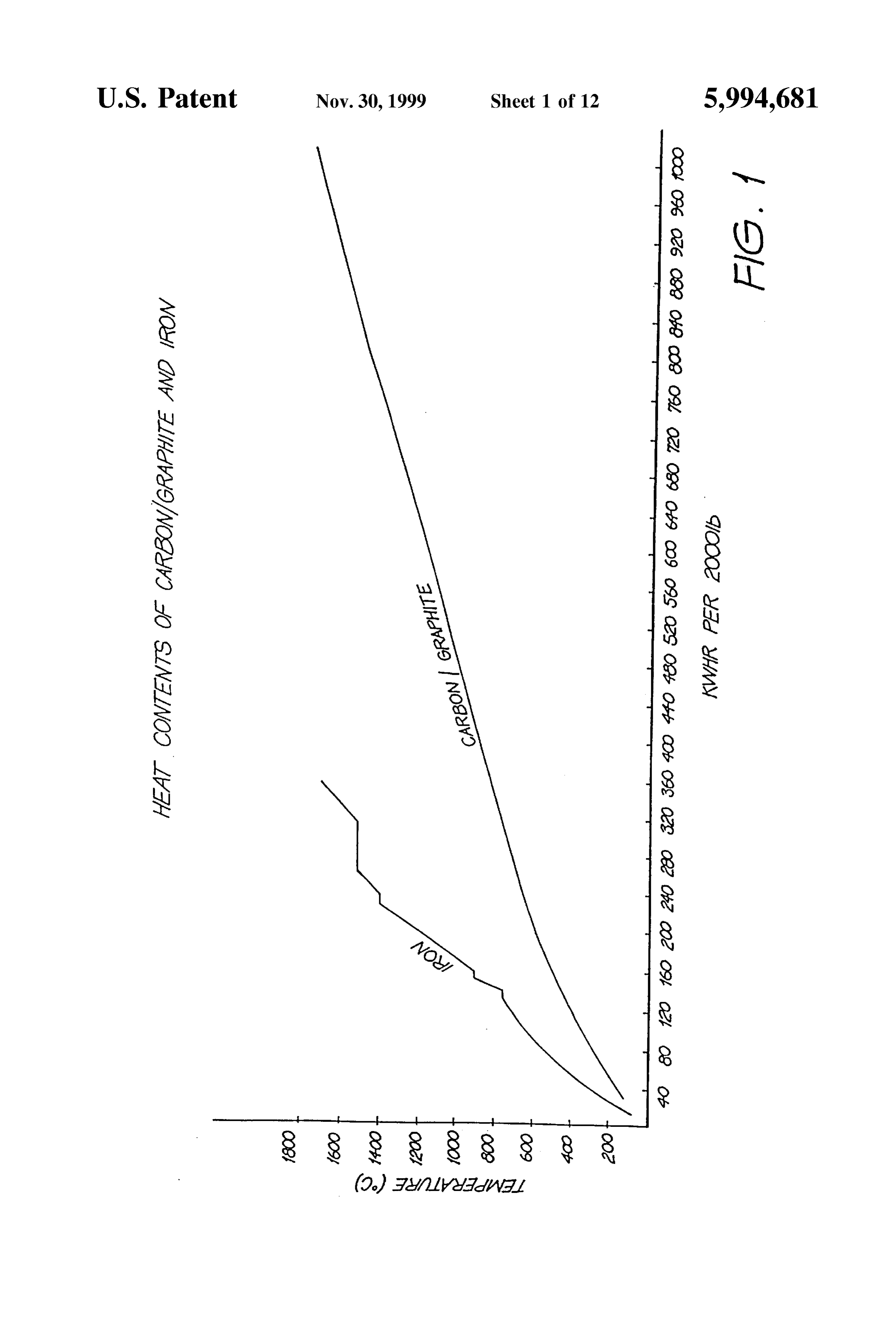
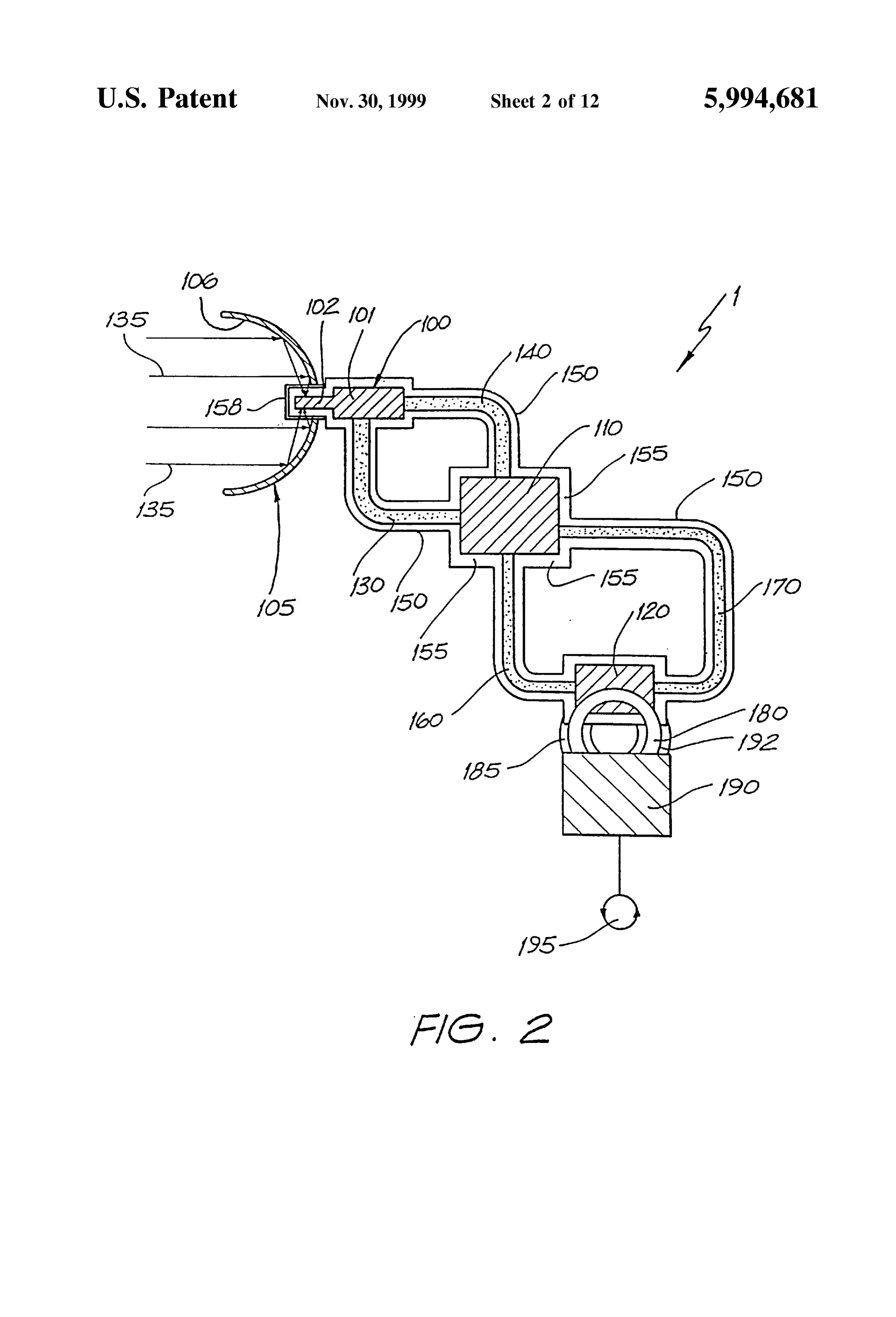
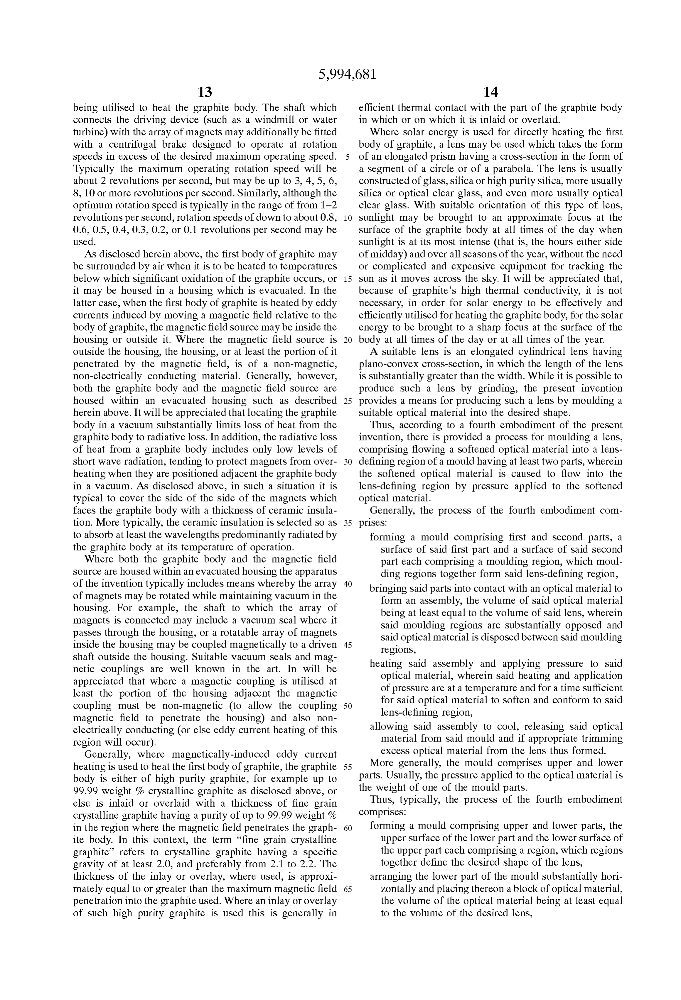
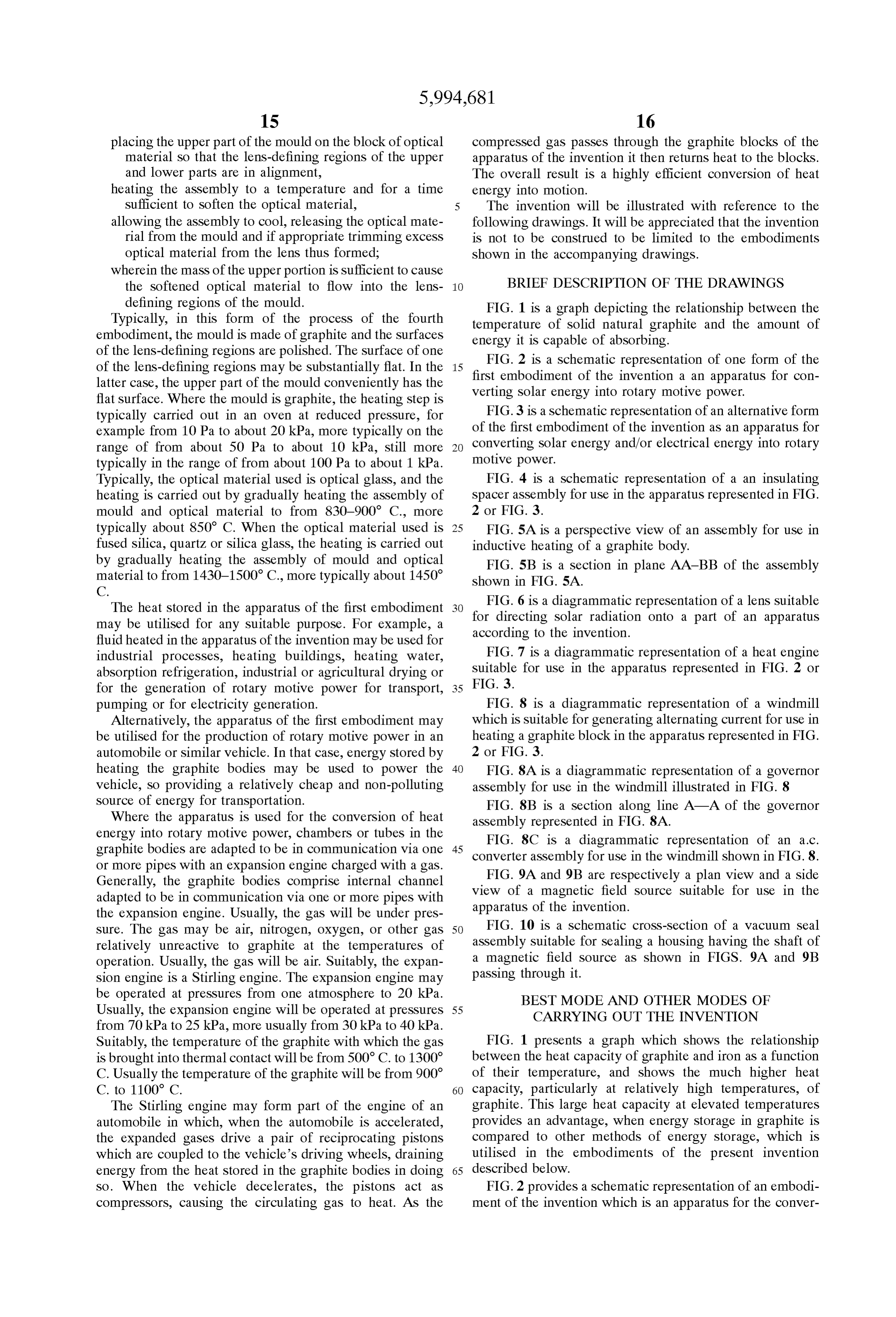
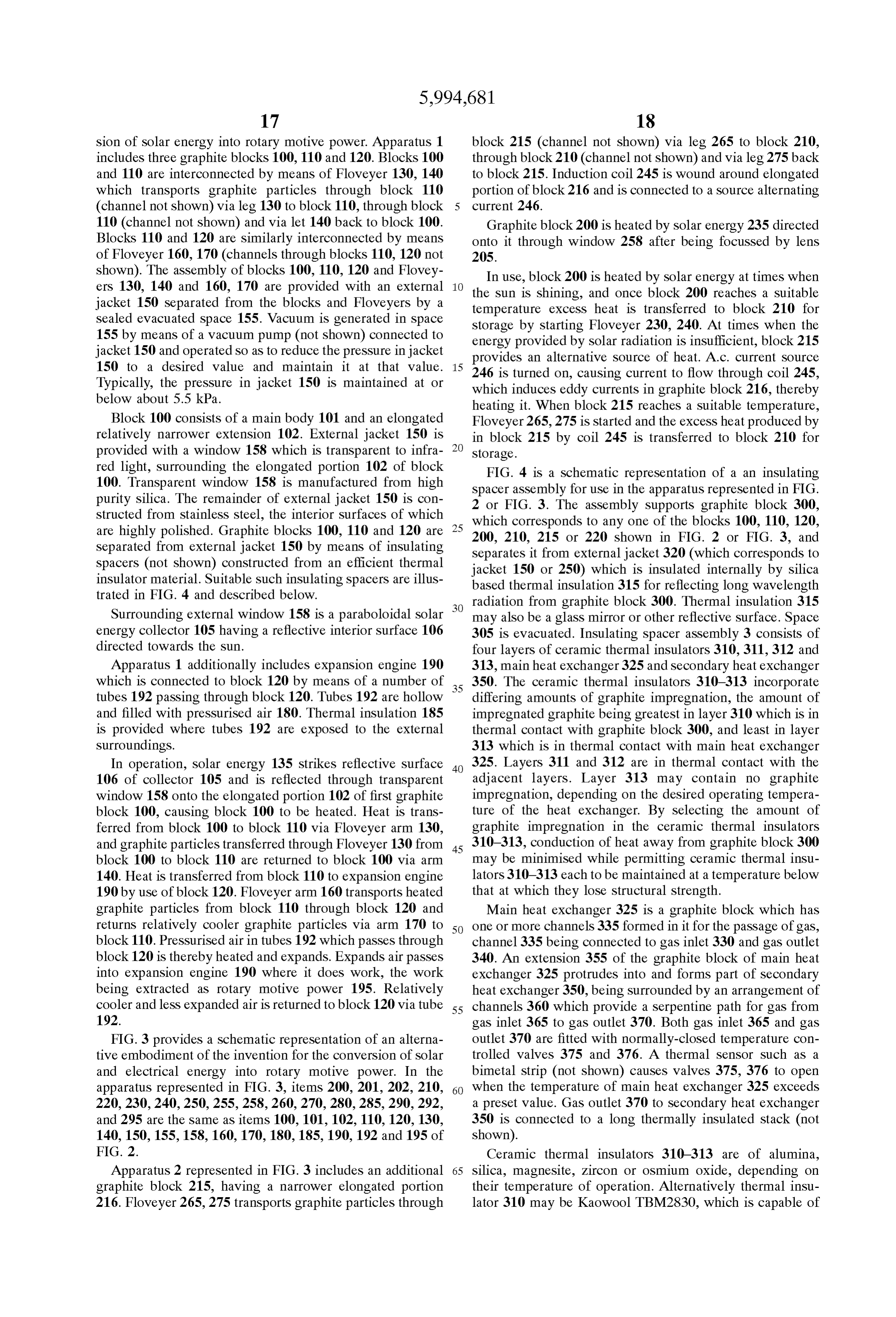
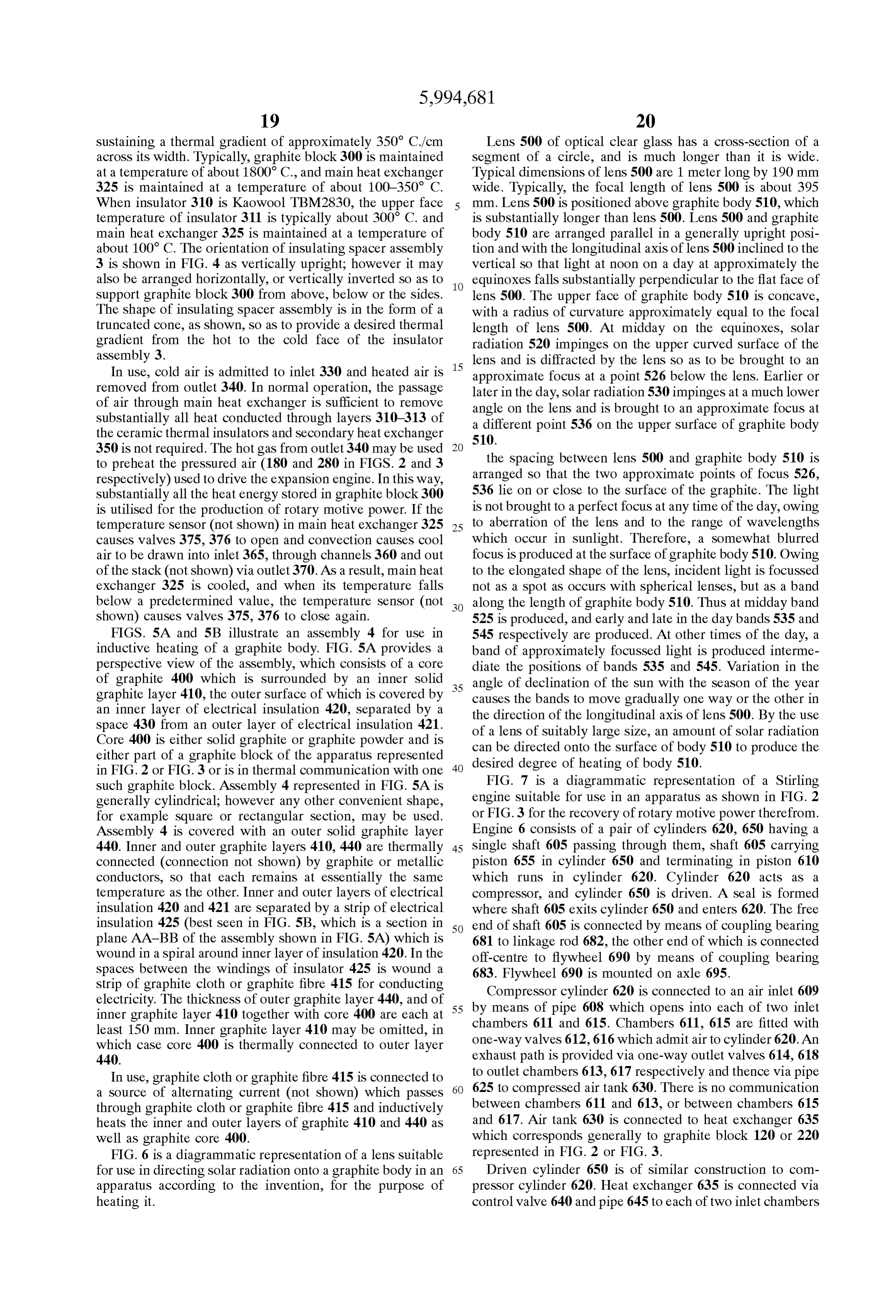
Sufficient to Soften the optical material, The invention will be illustrated with reference to the allowing the assembly to cool, releasing the optical mate following drawings. It will be appreciated that the invention rial from the mould and if appropriate trimming exceSS is not to be construed to be limited to the embodiments optical material from the lens thus formed; shown in the accompanying drawings. wherein the mass of the upper portion is Sufficient to cause the softened optical material to flow into the lens BRIEF DESCRIPTION OF THE DRAWINGS defining regions of the mould. FIG. 1 is a graph depicting the relationship between the Typically, in this form of the process of the fourth temperature of Solid natural graphite and the amount of embodiment, the mould is made of graphite and the Surfaces energy it is capable of absorbing.
of the lens-defining regions are polished. The Surface of one of the lens-defining regions may be Substantially flat. In the 15 FIG. 2 is a schematic representation of one form of the first embodiment of the invention a an apparatus for con latter case, the upper part of the mould conveniently has the Verting flat Surface. Where the mould is graphite, the heating Step is Solar energy into rotary motive power. typically carried out in an oven at reduced preSSure, for FIG. 3 is a schematic representation of an alternative form example from 10 Pa to about 20 kPa, more typically on the of the first embodiment of the invention as an apparatus for range of from about 50 Pa to about 10 kPa, still more converting Solar energy and/or electrical energy into rotary typically in the range of from about 100 Pa to about 1 kPa. motive power.
Typically, the optical material used is optical glass, and the FIG. 4 is a Schematic representation of a an insulating heating is carried out by gradually heating the assembly of Spacer assembly for use in the apparatus represented in FIG. mould and optical material to from 830–900 C., more 2 or FIG. 3.
typically about 850 C. When the optical material used is 25 FIG. 5A is a perspective view of an assembly for use in fused Silica, quartz or Silica glass, the heating is carried out inductive heating of a graphite body. by gradually heating the assembly of mould and optical FIG. 5B is a section in plane AA-BB of the assembly material to from 1430-1500° C., more typically about 1450° shown in FIG. 5A.
The heat stored in the apparatus of the first embodiment FIG. 6 is a diagrammatic representation of a lens Suitable may be utilised for any Suitable purpose. For example, a for directing Solar radiation onto a part of an apparatus according to the invention.
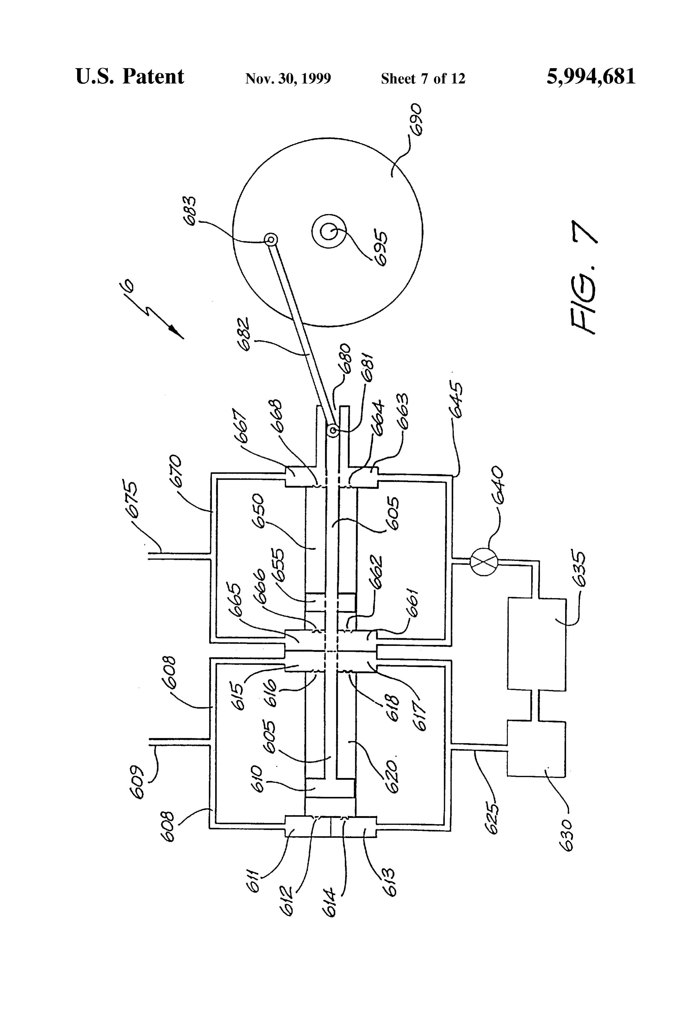
fluid heated in the apparatus of the invention may be used for industrial processes, heating buildings, heating Water, FIG. 7 is a diagrammatic representation of a heat engine absorption refrigeration, industrial or agricultural drying or Suitable for use in the apparatus represented in FIG. 2 or for the generation of rotary motive power for transport, 35 FIG. 3.
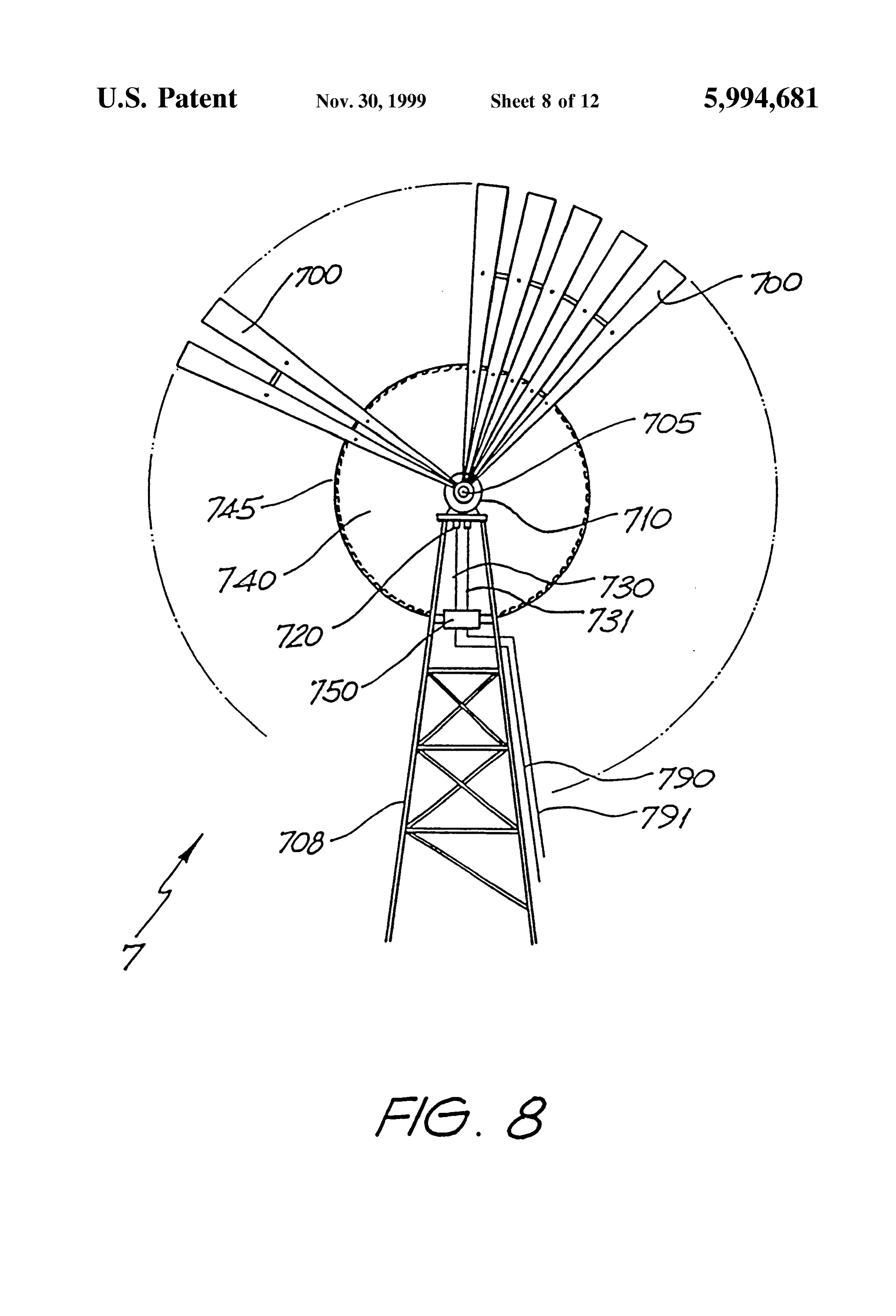
pumping or for electricity generation. FIG. 8 is a diagrammatic representation of a windmill Alternatively, the apparatus of the first embodiment may which is Suitable for generating alternating current for use in be utilised for the production of rotary motive power in an heating a graphite block in the apparatus represented in FIG. automobile or Similar vehicle. In that case, energy Stored by 2 or FIG. 3.
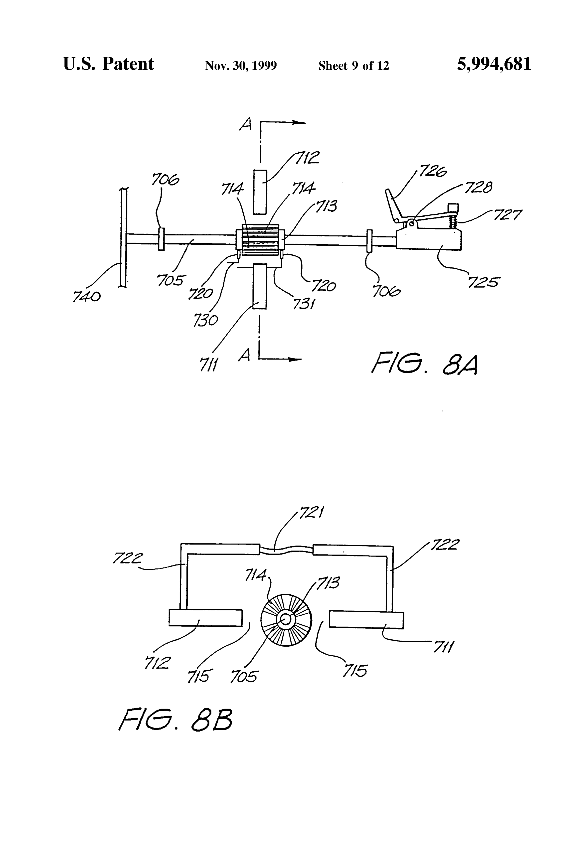
heating the graphite bodies may be used to power the 40 FIG. 8A is a diagrammatic representation of a governor vehicle, So providing a relatively cheap and non-polluting assembly for use in the windmill illustrated in FIG. 8 Source of energy for transportation. FIG. 8B is a section along line A-A of the governor Where the apparatus is used for the conversion of heat assembly represented in FIG. 8A.
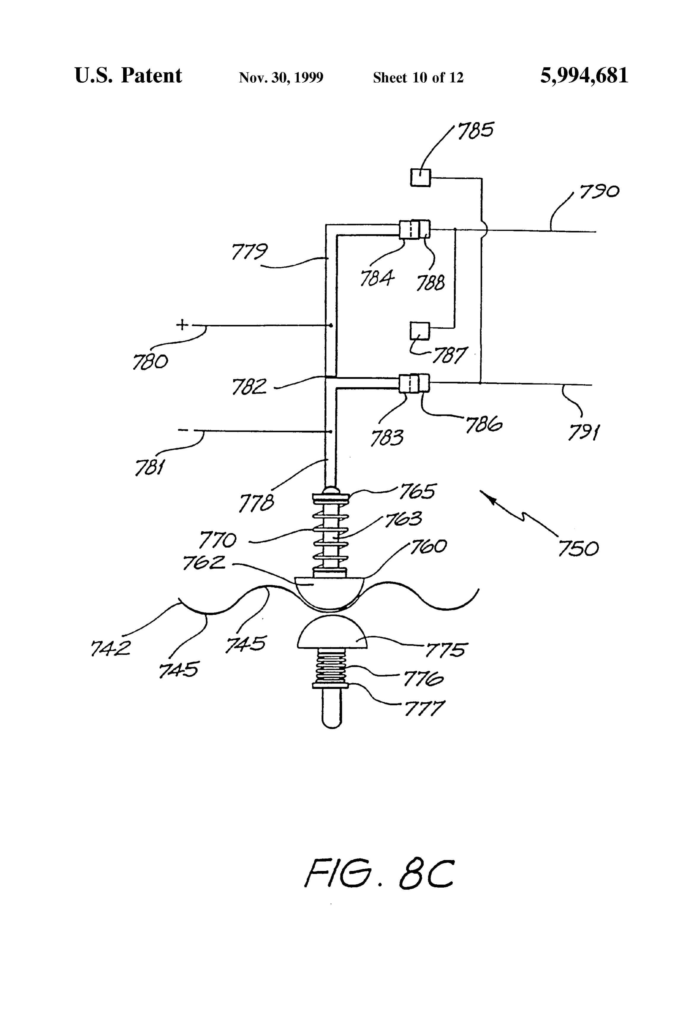
energy into rotary motive power, chambers or tubes in the FIG. 8C is a diagrammatic representation of an a.c. graphite bodies are adapted to be in communication via one 45 converter assembly for use in the windmill shown in FIG.8. or more pipes with an expansion engine charged with a gas.
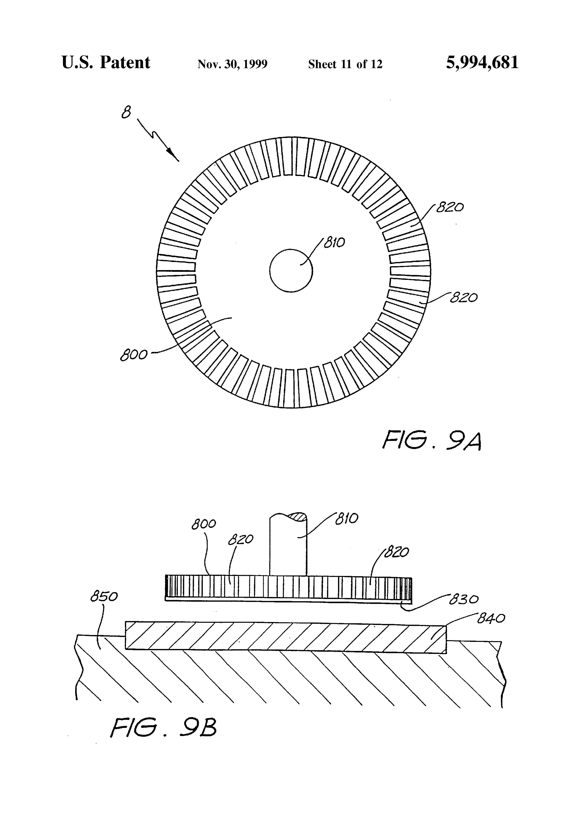
Generally, the graphite bodies comprise internal channel FIG. 9A and 9B are respectively a plan view and a side adapted to be in communication via one or more pipes with View of a magnetic field Source Suitable for use in the the expansion engine. Usually, the gas will be under pres apparatus of the invention.
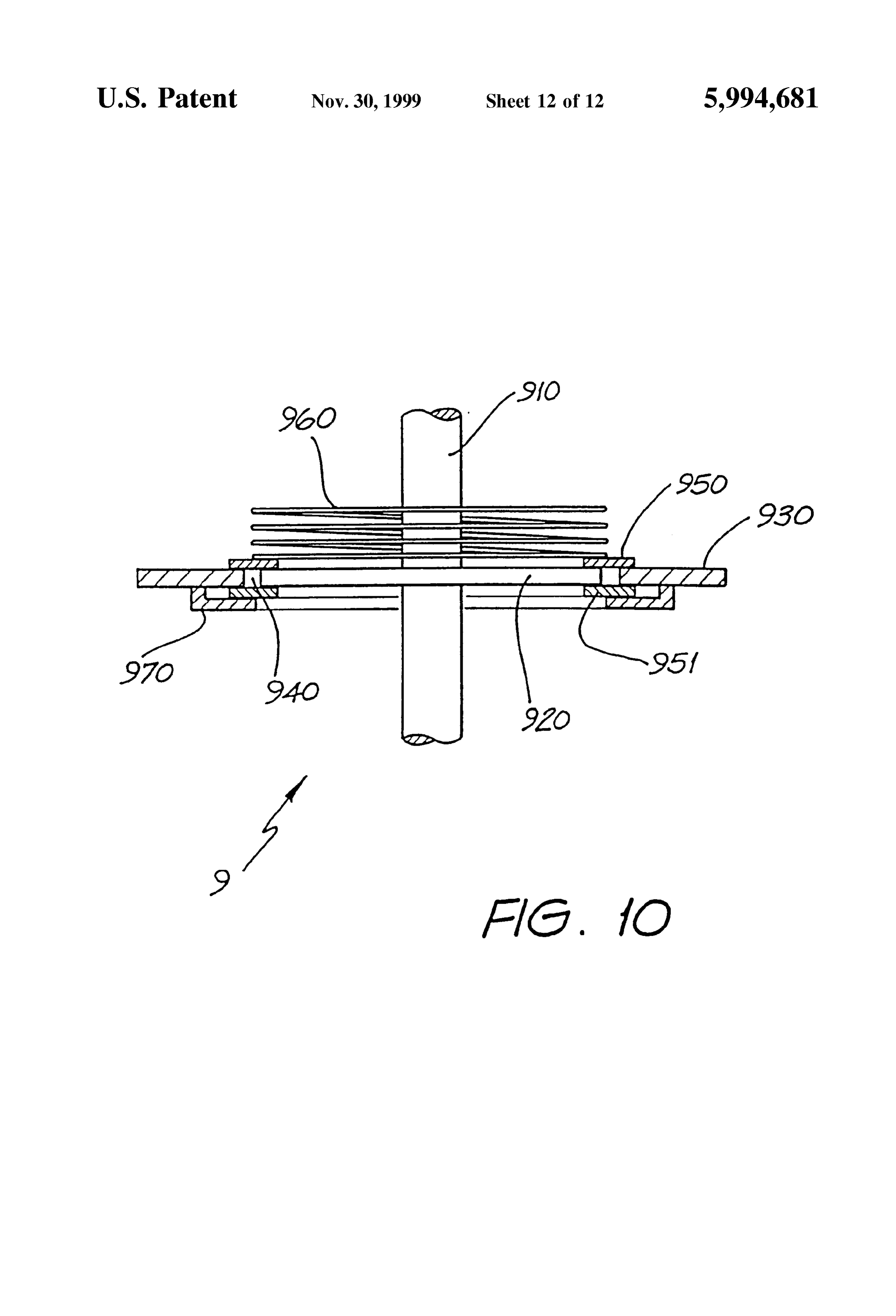
Sure. The gas may be air, nitrogen, Oxygen, or other gas 50 FIG. 10 is a Schematic cross-section of a vacuum Seal relatively unreactive to graphite at the temperatures of assembly Suitable for Sealing a housing having the shaft of operation. Usually, the gas will be air. Suitably, the expan a magnetic field source as shown in FIGS. 9A and 9B Sion engine is a Stirling engine. The expansion engine may passing through it.
be operated at pressures from one atmosphere to 20 kPa. BEST MODE AND OTHER MODES OF Usually, the expansion engine will be operated at pressures 55 CARRYING OUT THE INVENTION from 70 kPa to 25 kPa, more usually from 30 kPa to 40 kPa.
Suitably, the temperature of the graphite with which the gas FIG. 1 presents a graph which shows the relationship is brought into thermal contact will be from 500° C. to 1300 between the heat capacity of graphite and iron as a function C. Usually the temperature of the graphite will be from 900 of their temperature, and shows the much higher heat C. to 1100° C. 60 capacity, particularly at relatively high temperatures, of The Stirling engine may form part of the engine of an graphite. This large heat capacity at elevated temperatures automobile in which, when the automobile is accelerated, provides an advantage, when energy Storage in graphite is the expanded gases drive a pair of reciprocating pistons compared to other methods of energy Storage, which is which are coupled to the vehicle's driving wheels, draining utilised in the embodiments of the present invention energy from the heat Stored in the graphite bodies in doing 65 described below.
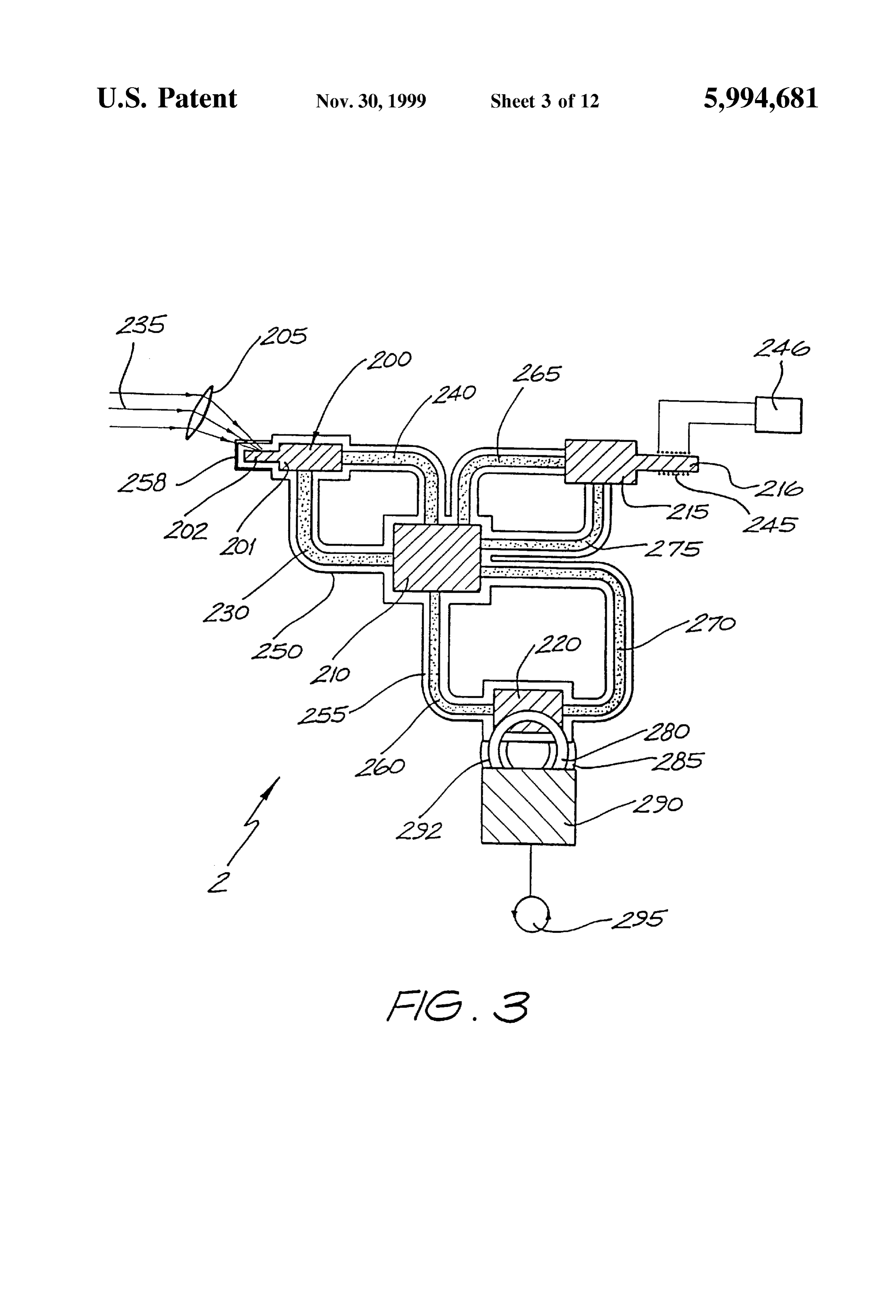
So. When the vehicle decelerates, the pistons act as FIG. 2 provides a Schematic representation of an embodi compressors, causing the circulating gas to heat. AS the ment of the invention which is an apparatus for the conver
Page 23
Sion of Solar energy into rotary motive power. Apparatus 1 block 215 (channel not shown) via leg 265 to block 210, includes three graphite blocks 100, 110 and 120. Blocks 100 through block 210 (channel not shown) and via leg 275 back and 110 are interconnected by means of Floveyer 130, 140 to block 215. Induction coil 245 is wound around elongated which transports graphite particles through block 110 portion of block 216 and is connected to a Source alternating (channel not shown) via leg 130 to block 110, through block current 246.
110 (channel not shown) and via let 140 back to block 100. Graphite block 200 is heated by solar energy 235 directed Blocks 110 and 120 are similarly interconnected by means onto it through window 258 after being focussed by lens of Floveyer 160, 170 (channels through blocks 110, 120 not 205.
shown). The assembly of blocks 100, 110, 120 and Flovey In use, block 200 is heated by Solar energy at times when ers 130, 140 and 160, 170 are provided with an external the Sun is shining, and once block 200 reaches a suitable jacket 150 separated from the blocks and Floveyers by a temperature excess heat is transferred to block 210 for Sealed evacuated Space 155. Vacuum is generated in Space storage by starting Floveyer 230, 240. At times when the 155 by means of a vacuum pump (not shown) connected to energy provided by Solar radiation is insufficient, block 215 jacket 150 and operated So as to reduce the pressure in jacket provides an alternative Source of heat. A.c. current Source 150 to a desired value and maintain it at that value. 15
Typically, the pressure in jacket 150 is maintained at or 246 which is turned on, causing current to flow through coil 245, induces eddy currents in graphite block 216, thereby below about 5.5 kPa.
heating it. When block 215 reaches a suitable temperature,
Block 100 consists of a main body 101 and an elongated Floveyer 265,275 is started and the excess heat produced by relatively narrower extension 102. External jacket 150 is in block 215 by coil 245 is transferred to block 210 for provided with a window 158 which is transparent to infra Storage.
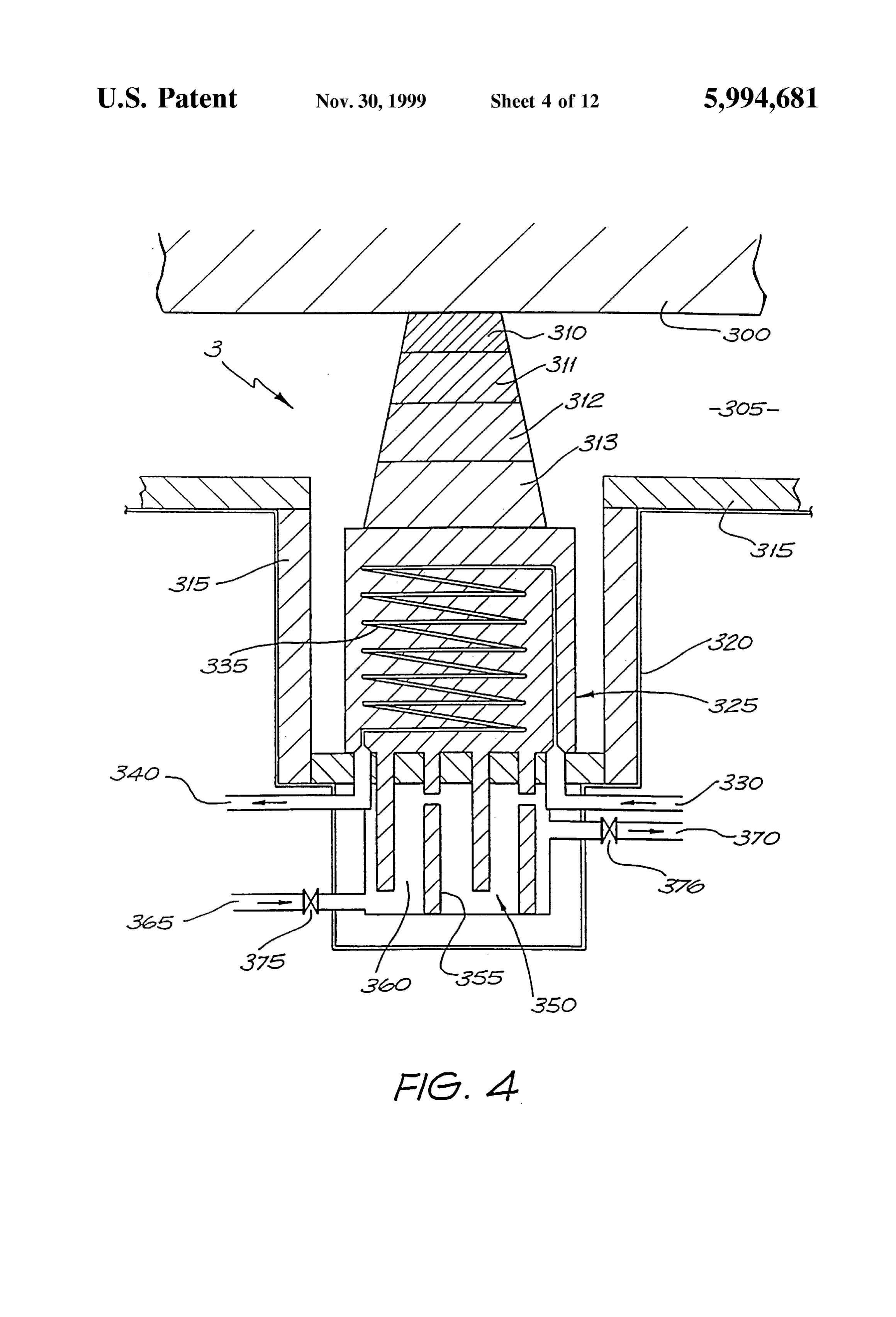
red light, Surrounding the elongated portion 102 of block FIG. 4 is a Schematic representation of a an insulating 100. Transparent window 158 is manufactured from high Spacer assembly for use in the apparatus represented in FIG. purity silica. The remainder of external jacket 150 is con 2 or FIG. 3. The assembly supports graphite block 300, Structed from StainleSS Steel, the interior Surfaces of which are highly polished. Graphite blocks 100, 110 and 120 are 25 which corresponds to any one of the blocks 100, 110, 120, Separated from external jacket 150 by means of insulating Separates it215
from external jacket 320 (which corresponds to
Spacers (not shown) constructed from an efficient thermal jacket 150 or 250) which is insulated internally by silica insulator material. Suitable Such insulating Spacers are illus based thermal insulation 315 for reflecting long wavelength trated in FIG. 4 and described below.
radiation from graphite block 300. Thermal insulation 315
Surrounding external window 158 is a paraboloidal Solar may also be a glass mirror or other reflective Surface. Space energy collector 105 having a reflective interior surface 106 305 is evacuated. Insulating spacer assembly 3 consists of directed towards the Sun. four layers of ceramic thermal insulators 310, 311, 312 and Apparatus 1 additionally includes expansion engine 190 313, main heat eXchanger 325 and Secondary heat eXchanger which is connected to block 120 by means of a number of 35 350. The ceramic thermal insulators 310-313 incorporate tubes 192 passing through block 120. Tubes 192 are hollow differing amounts of graphite impregnation, the amount of and filled with pressurised air 180. Thermal insulation 185 impregnated graphite being greatest in layer 310 which is in is provided where tubes 192 are exposed to the external thermal contact with graphite block 300, and least in layer Surroundings. 313 which is in thermal contact with main heat exchanger In operation, Solar energy 135 Strikes reflective Surface 40 325. Layers 311 and 312 are in thermal contact with the 106 of collector 105 and is reflected through transparent adjacent layers. Layer 313 may contain no graphite window 158 onto the elongated portion 102 of first graphite impregnation, depending on the desired operating tempera block 100, causing block 100 to be heated. Heat is trans ture of the heat eXchanger. By Selecting the amount of ferred from block 100 to block 110 via Floveyer arm 130, graphite impregnation in the ceramic thermal insulators and graphite particles transferred through Floveyer 130 from 45 310-313, conduction of heat away from graphite block 300 block 100 to block 110 are returned to block 100 via arm may be minimised while permitting ceramic thermal insu 140. Heat is transferred from block 110 to expansion engine lators 310-313 each to be maintained at a temperature below 190 by use of block 120. Floveyer arm 160 transports heated that at which they lose Structural Strength. graphite particles from block 110 through block 120 and Main heat exchanger 325 is a graphite block which has returns relatively cooler graphite particles via arm 170 to 50 one or more channels 335 formed in it for the passage of gas, block 110. Pressurised air in tubes 192 which passes through channel 335 being connected to gas inlet 330 and gas outlet block 120 is thereby heated and expands. Expands air passes 340. An extension 355 of the graphite block of main heat into expansion engine 190 where it does work, the work eXchanger 325 protrudes into and forms part of Secondary being extracted as rotary motive power 195. Relatively heat eXchanger 350, being Surrounded by an arrangement of cooler and less expanded air is returned to block 120 via tube 55 channels 360 which provide a serpentine path for gas from 192. gas inlet 365 to gas outlet 370. Both gas inlet 365 and gas FIG. 3 provides a Schematic representation of an alterna outlet 370 are fitted with normally-closed temperature con tive embodiment of the invention for the conversion of Solar trolled valves 375 and 376. A thermal sensor Such as a and electrical energy into rotary motive power. In the bimetal strip (not shown) causes valves 375, 376 to open apparatus represented in FIG. 3, items 200, 201, 202, 210, 60 when the temperature of main heat eXchanger 325 exceeds 220, 230, 240,250, 255, 258, 260,270, 280, 285,290,292, a preset value. Gas outlet 370 to Secondary heat eXchanger and 295 are the same as items 100, 101, 102,110, 120, 130, 350 is connected to a long thermally insulated stack (not 140, 150, 155, 158, 160, 170, 180,185, 190,192 and 195 of shown).
FIG. 2. Ceramic thermal insulators 310-313 are of alumina, Apparatus 2 represented in FIG. 3 includes an additional 65 Silica, magnesite, Zircon or osmium oxide, depending on graphite block 215, having a narrower elongated portion their temperature of operation. Alternatively thermal insu 216. Floveyer 265,275 transports graphite particles through lator 310 may be Kaowool TBM2830, which is capable of
Page 24
Sustaining a thermal gradient of approximately 350° C./cm Lens 500 of optical clear glass has a cross-section of a across its width. Typically, graphite block 300 is maintained Segment of a circle, and is much longer than it is wide. at a temperature of about 1800 C., and main heat exchanger Typical dimensions of lens 500 are 1 meter long by 190 mm 325 is maintained at a temperature of about 100-350° C. wide. Typically, the focal length of lens 500 is about 395 When insulator 310 is Kaowool TBM2830, the upper face mm. Lens 500 is positioned above graphite body 510, which temperature of insulator 311 is typically about 300° C. and is substantially longer than lens 500. Lens 500 and graphite main heat eXchanger 325 is maintained at a temperature of body 510 are arranged parallel in a generally upright posi about 100° C. The orientation of insulating spacer assembly tion and with the longitudinal axis of lens 500 inclined to the 3 is shown in FIG. 4 as vertically upright; however it may Vertical So that light at noon on a day at approximately the also be arranged horizontally, or vertically inverted So as to 1O equinoxes falls Substantially perpendicular to the flat face of support graphite block 300 from above, below or the sides. lens 500. The upper face of graphite body 510 is concave, The shape of insulating Spacer assembly is in the form of a with a radius of curvature approximately equal to the focal truncated cone, as shown, So as to provide a desired thermal length of lens 500. At midday on the equinoxes, solar gradient from the hot to the cold face of the insulator radiation 520 impinges on the upper curved Surface of the assembly 3. lens and is diffracted by the lens so as to be brought to an In use, cold air is admitted to inlet 330 and heated air is 15 approximate focus at a point 526 below the lens. Earlier or removed from outlet 340. In normal operation, the passage later in the day, Solar radiation 530 impinges at a much lower of air through main heat eXchanger is Sufficient to remove angle on the lens and is brought to an approximate focus at substantially all heat conducted through layers 310-313 of a different point 536 on the upper surface of graphite body the ceramic thermal insulators and Secondary heat eXchanger 510.
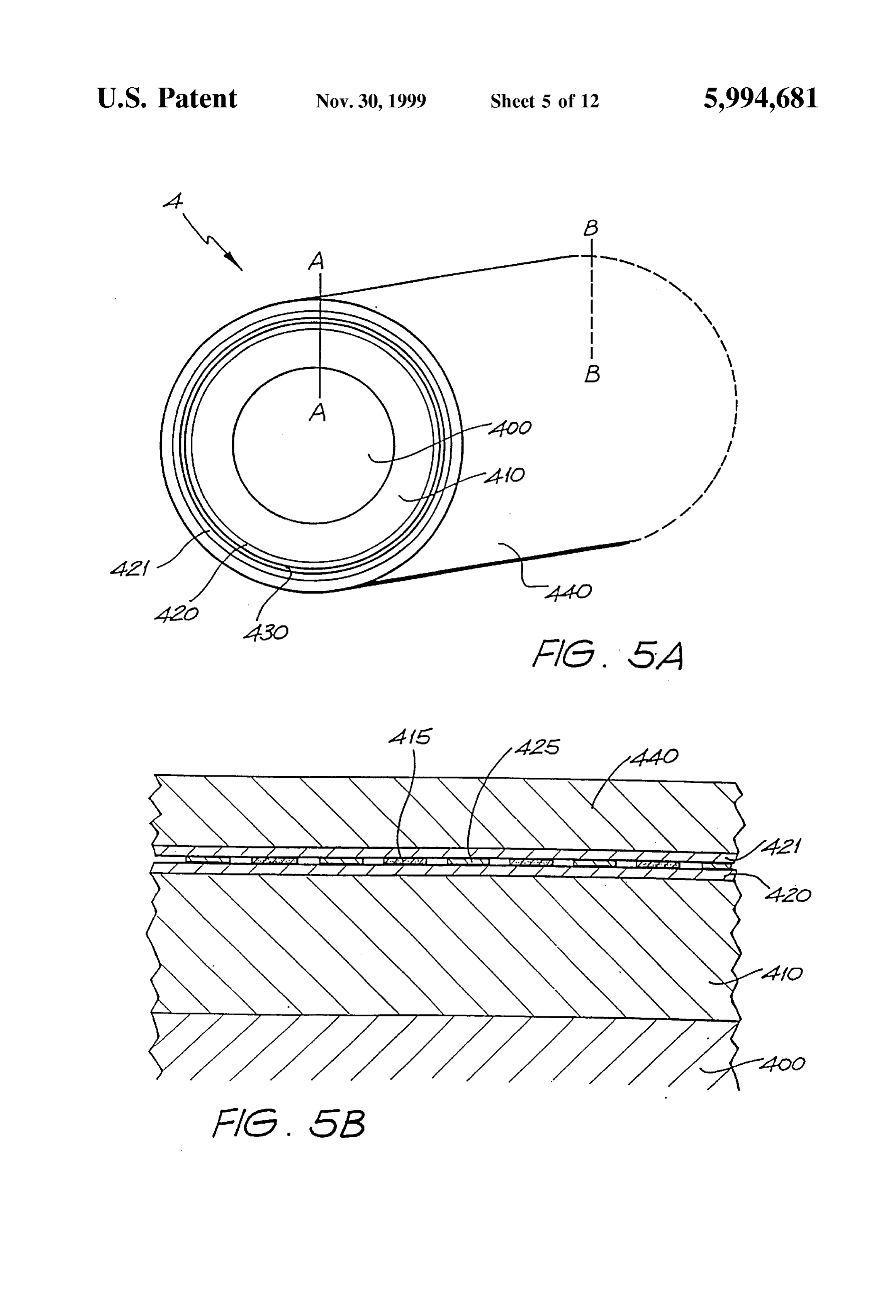
350 is not required. The hot gas from outlet 340 may be used the spacing between lens 500 and graphite body 510 is to preheat the pressured air (180 and 280 in FIGS. 2 and 3 arranged So that the two approximate points of focus 526, respectively) used to drive the expansion engine. In this way, substantially all the heat energy stored in graphite block 300 536 lie on or close to the surface of the graphite. The light is utilised for the production of rotary motive power. If the is not brought to a perfect focus at any time of the day, owing temperature Sensor (not shown) in main heat exchanger 325 25 to aberration of the lens and to the range of wavelengths causes valves 375, 376 to open and convection causes cool which occur in Sunlight. Therefore, a somewhat blurred air to be drawn into inlet 365, through channels 360 and out focus is produced at the surface of graphite body 510. Owing of the stack (not shown) via outlet 370. As a result, main heat to the elongated shape of the lens, incident light is focussed eXchanger 325 is cooled, and when its temperature falls not as a Spot as occurs with Spherical lenses, but as a band below a predetermined value, the temperature Sensor (not along the length of graphite body 510. Thus at midday band shown) causes valves 375, 376 to close again. 525 is produced, and early and late in the day bands 535 and FIGS. 5A and 5B illustrate an assembly 4 for use in 545 respectively are produced. At other times of the day, a inductive heating of a graphite body. FIG. 5A provides a band of approximately focussed light is produced interme perspective view of the assembly, which consists of a core diate the positions of bands 535 and 545. Variation in the of graphite 400 which is surrounded by an inner solid 35 angle of declination of the Sun with the Season of the year graphite layer 410, the outer surface of which is covered by causes the bands to move gradually one way or the other in an inner layer of electrical insulation 420, Separated by a space 430 from an outer layer of electrical insulation 421. the direction of the longitudinal axis of lens 500. By the use Core 400 is either solid graphite or graphite powder and is of a lens of Suitably large size, an amount of Solar radiation either part of a graphite block of the apparatus represented can be directed onto the surface of body 510 to produce the in FIG. 2 or FIG.3 or is in thermal communication with one 40 desired degree of heating of body 510. such graphite block. Assembly 4 represented in FIG. 5A is FIG. 7 is a diagrammatic representation of a Stirling generally cylindrical; however any other convenient shape, engine Suitable for use in an apparatus as shown in FIG. 2 for example Square or rectangular Section, may be used. or FIG.3 for the recovery of rotary motive power therefrom. ASSembly 4 is covered with an outer Solid graphite layer Engine 6 consists of a pair of cylinders 620, 650 having a 440. Inner and outer graphite layers 410, 440 are thermally 45 single shaft 605 passing through them, shaft 605 carrying connected (connection not shown) by graphite or metallic piston 655 in cylinder 650 and terminating in piston 610 conductors, So that each remains at essentially the same which runs in cylinder 620. Cylinder 620 acts as a temperature as the other. Inner and Outer layers of electrical compressor, and cylinder 650 is driven. A seal is formed insulation 420 and 421 are separated by a strip of electrical where shaft 605 exits cylinder 650 and enters 620. The free insulation 425 (best seen in FIG. 5B, which is a section in 50 end of shaft 605 is connected by means of coupling bearing plane AA-BB of the assembly shown in FIG. 5A) which is 681 to linkage rod 682, the other end of which is connected wound in a spiral around inner layer of insulation 420. In the off-centre to flywheel 690 by means of coupling bearing Spaces between the windings of insulator 425 is wound a 683. Flywheel 690 is mounted on axle 695.
Strip of graphite cloth or graphite fibre 415 for conducting electricity. The thickness of outer graphite layer 440, and of 55 byCompressor cylinder 620 is connected to an air inlet 609 means of pipe 608 which opens into each of two inlet inner graphite layer 410 together with core 400 are each at chambers 611 and 615. Chambers 611, 615 are fitted with least 150 mm. Inner graphite layer 410 may be omitted, in which case core 400 is thermally connected to outer layer one-way valves 612, 616 which admit air to cylinder 620. An 440. exhaust path is provided via one-way outlet valves 614, 618 In use, graphite cloth or graphite fibre 415 is connected to to outlet chambers 613, 617 respectively and thence via pipe a Source of alternating current (not shown) which passes 60 625 to compressed air tank 630. There is no communication through graphite cloth or graphite fibre 415 and inductively between chambers 611 and 613, or between chambers 615 heats the inner and outer layers of graphite 410 and 440 as and 617. Air tank 630 is connected to heat exchanger 635 well as graphite core 400. which corresponds generally to graphite block 120 or 220 FIG. 6 is a diagrammatic representation of a lens Suitable represented in FIG. 2 or FIG. 3.
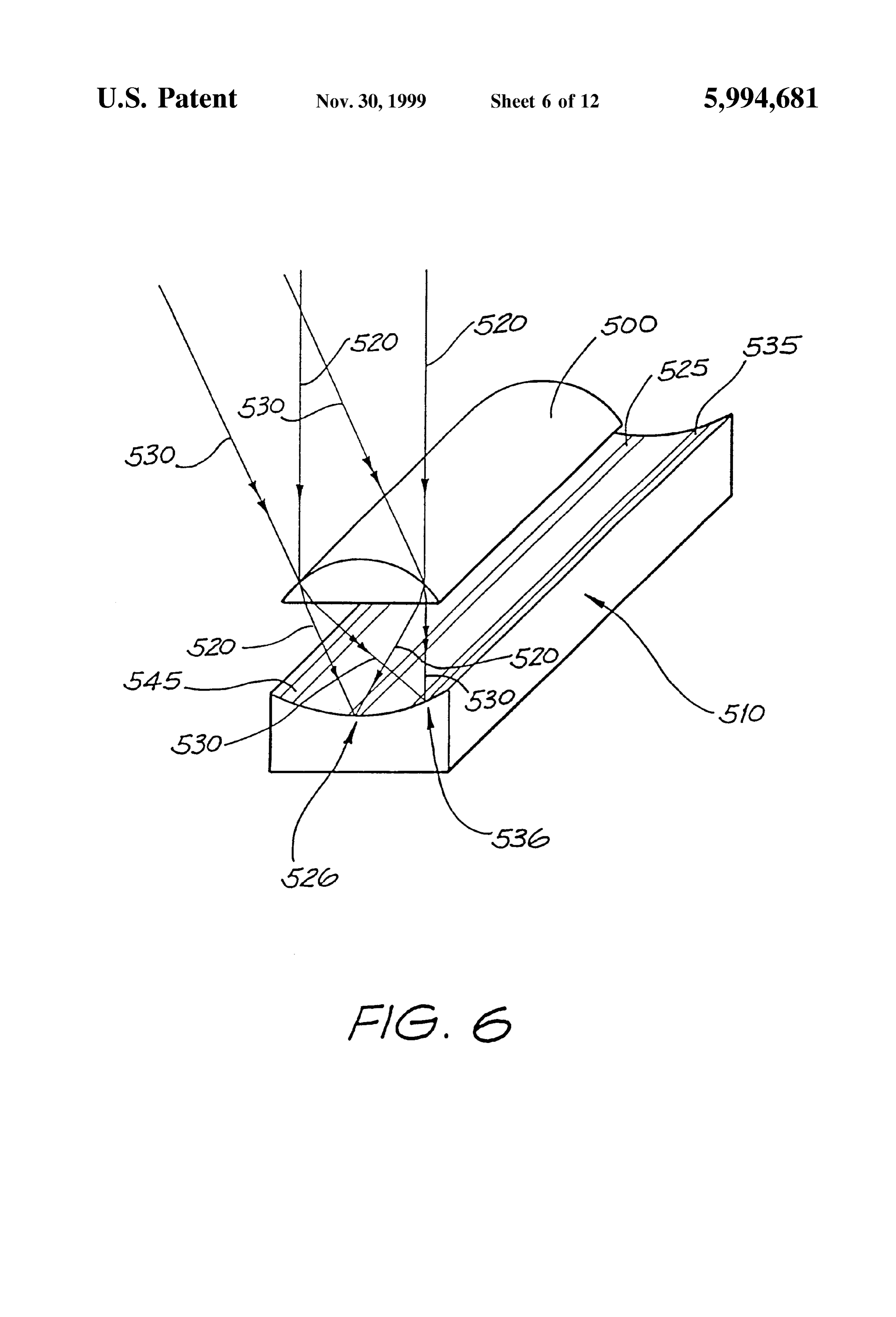
for use in directing Solar radiation onto a graphite body in an 65 Driven cylinder 650 is of similar construction to com apparatus according to the invention, for the purpose of pressor cylinder 620. Heat exchanger 635 is connected via heating it. control valve 640 and pipe 645 to each of two inlet chambers
Page 25
661, 663, which are equipped with inlet valves 662, 664 consists of a rotor body 713 carrying windings 714, posi respectively. Chambers 665,667, fitted with exhaust valves tioned between the poles 711, 712 of a magnet. Windings 666,668 respectively provide a path via pipe 670 to exhaust 714 terminate on conductive Surfaces at the ends of rotor outlet 675. Valves 662, 664, 666 and 668 are operated by 713, which are contracted by a pair brushes 720, carrying means of cams on a cam rod (not shown) coupled by gears wires 730, 731 which conduct d.c. generated by the wind to axle 695 of flywheel 690. mill. At the end of shaft 705 remote from disc or ring 740 In operation, motion of shaft 605 towards the left as is mounted a governor assembly 725 which includes a shown in FIG. 7 causes inlet valve 616 to open and inlet generally L-shaped actuator lever 726 (only part shown) valve 612 to close. Air is drawn into cylinder 620 behind mounted on pivot 728. The shorter arm of actuator 726 is moving piston 610, and air ahead of piston 610 is com separated from the body of governor 725 by spring 727. In pressed until pressure in cylinder 620 causes valve 614 to FIG. 8A, the whole length of the longer arm of actuator is open, whereupon compressed air is displaced into tank 630 not shown. The free end of this longer arm is connected to and thence through heat exchanger 635. On the return the two poles 711, 712 of the magnet is such a way that Stroke, operation of compressor cylinder 620 is similar, movement of the longer arm of actuator 726 in one direction except that air is drawn through valve 612, with valve 616 15 causes poles 711, 712 to move apart, and movement of the being closed, and compressed air is displaced through valve longer arm of actuator 726 in the other direction causes poles 618, with valve 614 being closed. 711, 712 to move together. Poles 711 and 712 are connected Compressed air entering heat eXchanger 635 is heated and by means of struts 722 and flexible link 721, as seen in FIG. expands. Expanded air passes via valve 640 and pipe 645 8B (not shown in FIG. 8A).
into chamber 663. The cam arrangement on the cam rod (not In operation, with blades 700 of windmill 7 stationary, shown) causes inlet valve 664 and exhaust valve 666 to be poles 711 and 712 are relatively far apart. Consequently the open, and valves 662 and 668 to be closed. The entry of air space 715 (see FIG.8B) between poles 711,712 and rotor expanded air into cylinder 650 via valve 664 causes piston windings 714 is relatively large and the magnetic field 655 and shaft 605 to be displaced to the left, resulting in experienced by windings 714 is relatively small. When the rotation of flywheel 690 in an anticlockwise direction. 25 wind blows, shaft 705 rotates with blades 700, causing rotor Expanded air is exhausted via valve 666 and pipe 670 to 713 and windings 714 to rotate in the magnetic field pro outlet 675. When piston 655 nears the end of its stroke, the duced between poles 711, 712 thereby generating a potential cam closes valves 664, 666 and opens valves 662 and 668, difference at brushes 720 and in wires 730, 731. When the causing piston 655 to be displaced to the right, with wind blows more strongly, the speed of rotation of shaft 705 expanded air entering cylinder Via Valve 662 and leaving via tends to increase. This increase in the Speed of rotation of valve 668. Rotation of flywheel 690 is thereby maintained in shaft 705 causes actuator 726 of governor 725 to move, and the anticlockwise direction. The net effect is removal of heat as a result, poles 711, 712 move also. The assembly is such from heat exchanger 635 and conversion of that heat to that as the speed of rotation of shaft 705 increases, poles 711, useful work in the form of rotation of the flywheel. Machin 712 are caused to move closer together. Thus, the intensity ery of various kinds may be driven by the rotation of axle 35 of the magnetic field experienced by windings 714 695. increases, and the potential difference between wires 730, FIG. 8 is a diagrammatic representation of a windmill 731 increases. Consequently, under these conditions, a larger which is Suitable for generating alternating current for use in d.c. may be drawn from generator 710. This direct current is heating a graphite block in the apparatus represented in FIG. substantially the only load on windmill 7 and produces a 2 or FIG. 3. Referring to FIG. 8, windmill 7 consists of a 40 braking effect which acts to prevent acceleration of the number of blades 700 (only some shown) which are windmill's rotation beyond a certain speed. At low wind designed and pitched at an angle So as to produce high Speeds, the magnetic field experienced by windingS 714 is torque at low speeds. Blades 700 are spaced evenly in a relatively small, since poles 711, 712 are under those con circular arrangement as is conventional in windmill design, ditions relatively far apart, and relatively little d.c. may be and are attached to and radiate from axle 705 which is 45 drawn from generator 710, placing only a Small load on the mounted on frame 708. Axle 705 drives a conventional d.c. windmill. As a result, the windmill tends to accelerate to, generator 710. Brushes 720 on the generator conduct elec and remain operating at, a Substantially constant rotation tricity from generator 710 via wires 730, 731 to a.c. con Speed. In this way it is possible to operate the windmill at verter assembly 750, which is described in more detail low wind speeds, down to as little as 0.5 m/s. below with reference to FIG. 8C. Alternating current is 50 FIG. 8C provides a detailed schematic representation of conducted from windmill 7 by wires 790,791. Also mounted a.c. converter assembly 750 shown in FIG.8. Assembly 750 on axle 705 is a disc or ring 740 having approximately 1000 consists of two followers 760, 775 which are positioned in sinusoidal undulations 745 around its periphery. Disc or ring contact with the front and back faces of disc or ring 740, a 740 may be metal or rigid plastic. It is preferably a ring, portion of which is shown at 742, in the region of its Supported in place by a number of radial Struts (not shown) 55 periphery which is undulated. Follower 760 has a shaft 763 connecting it to axle 705. Axle 705 also carries a governor passing through collar 765 which is fixed to frame 708 of assembly (not shown) which regulates the rotational speed windmill 7. Shaft 763 carries spring 770 which abuts the of the windmill. head 762 of follower 760 at one end, and fixed collar 765 at The mechanism whereby the rotational speed of windmill the other. Similarly, follower 775 carries spring 776 which 7 is regulated may be better understood by reference to 60 abuts fixed collar 777. The end of follower 760 remote from FIGS. 8A and 8B. FIG. 8A provides a diagrammatic repre its head 762 is connected to rigid conductors 778,779 which Sentation of the regulator assembly in plan view, and FIG. are separated by electrical insulator 782. Conductors 778, 8B provides a section along the line A-A in FIG. 8A. 779 terminate in d.c. contacts 783, 784 respectively and are Referring to FIG. 8A, shaft 705, which is seen end-on in electrically connected to flexible wires 781, 780 respec FIG. 8, is seen in plan view, with disc or ring 740 at one end. 65 tively. Wires 781, 780 are electrically connected to wires Shaft 705 is mounted for rotation in bearings 706 and carries 730, 731 of windmill 7. D.c. contacts 783, 784 are posi generator 710 mounted coaxially thereon. Generator 710 tioned So as to make sliding contact with one or another of
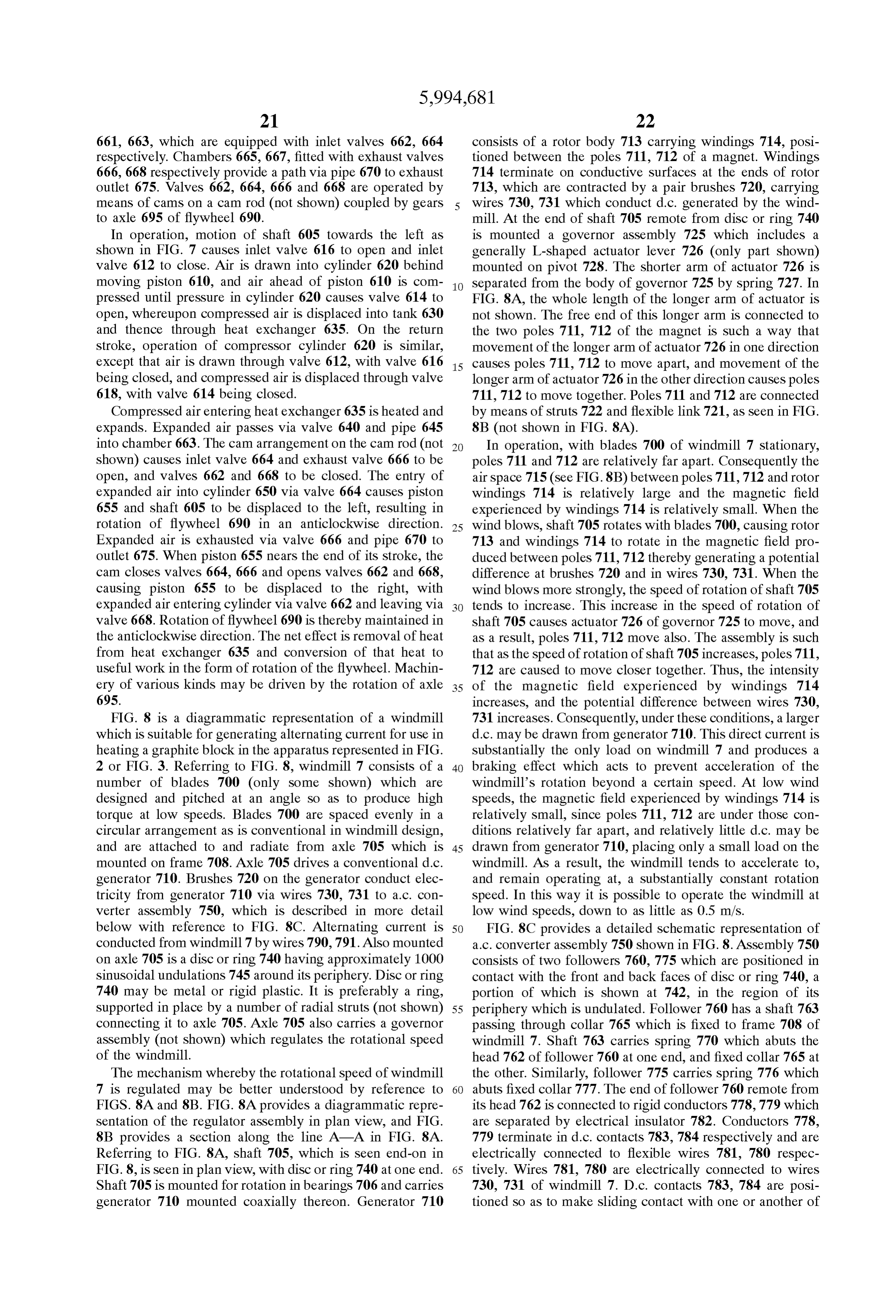
Page 26
a pair of a.c. contacts. Thus d.c. contact 783 is positioned So magnets 820 is thereby rotated relative to blocks 840 and as to make sliding contact with either a.c. contact 786 or 787, 850. The magnetic field of magnets 820 penetrates graphite and d.c. contact 784 is positioned So as to make Sliding block 840 and moves within block 840 as disk 800 moves. contact with either a.c. contact 785 or 788. A.c. contacts AS a result, the magnetic field Strength varies at any point 785–788 are electrically connected as shown in FIG. 8C. within the part of block 840 which is penetrated by the When windmill 7 is operated, rotation of blades 700 magnetic field, this variation in magnetic field Strength causes disc or ring 740 to rotate. As a result, undulations 745 inducing electric eddy currents in block 840 which, owing to pass between followers 760, 775, causing followers 760, the electrical resistance of the graphite, heat block 840. Heat in block 840 is conducted to block 850.
775 to move backwards and forwards along their shafts The rotation speed of shaft 810 may be controlled by a under the action of springs 770, 776. The function of Suitable governor mechanism (not shown) for example follower 775 is to maintain disc or ring 740 in contact with including a mechanism to increase and decrease the Space follower 760. The movement of follower 760 results in between insulating layer 830 and block 840 as previously corresponding movement of conductor 778 and d.c. contact described herein. Typically shaft 810 and disk 800 are 783, which is thus alternately positioned in contact with a.c. adjusted to rotate at approximately 60 revolutions per contacts 786 and 787. Correspondingly, d.c. contact 784 is 15 minute.
alternately positioned in contact with a.c. contacts 788 and This method heating block 850 has a number of advan 785 by virtue of the movement of conductor 779. Lead 790 tages when the source of energy driving shaft 810 is wind or is thus alternately positive and negative with respect to lead water movement, for example. In contrast to electrical 791. The frequency of alternation depends on the speed of inductive heating, there are no inductive heating coils, which rotation of windmill 7 and the number of undulations 745 in require expensive equipment to provide the necessary large disc or ring 740. In a typical arrangement, windmill 7 rotates current flow and which require cooling, with resultant loSS at about 50 revolutions per minute, and disc or ring 740 has of useful energy. Inductive heating coils are also inherently about 1000 undulations. The resulting a.c. frequency is thus less efficient, owing to losses due to eddy currents and approximately 800 Hz. heating which inevitably occur in the primary induction coil. In addition in the apparatus of the invention there is rela
FIGS. 9A and 9B respectively show a plan view and side 25 tively
Vie of a magnetic field Source Suitable for use in the put it little inertia or capacitance making it relatively easy to apparatus of the invention. Magnetic field Source 8 includes assembly atmotion into on Startup and making operation of the relatively low rotation Speeds possible. For generally circular disk 800 having a centrally located shaft example, in a typical arrangement, a wind Speed of as low 810 connected to it and having mounted near its periphery as 0.5 m/s is Sufficient to Sustain rotation of the magnetic 25 equally Spaced permanent magnets 820 of rare earth alloy field Source 8. Thus, useful energy may be extracted from a or niobium/iron. Disk 800 is positioned adjacent a face of windmill, for example, even at quite low wind Speeds. In essentially 100% fine grain crystalline graphite block 840 as addition magnetic field source 8 may be directly driven by seen in FIG. 9B, such that the magnetic fields of magnets a rotating device Such as a windmill or water turbine without 820 penetrate into block 840. Graphite block 840 is inlaid 35 the need for complicated linkages, gears or other mecha into a block 850 of approximately 95% graphite so that nisms which cause inefficiencies and energy losses. blocks 840 and 850 are in good thermal contact. The thickness of block 840 is greater than the depth of penetra 9BIfisaused magnetic field source such as shown in FIGS. 9A and to heat a graphite block which include insulating tion of the magnetic field of magnets 820 into block 840, and spacers as shown is typically at least approximately 5 cm. Graphite block 850 40 Seen in FIG. 4 mayinbeFIG. used 4, the heated air from outlet 340 to drive a Small expansion engine is fixed so that it does not rotate when disk 800 is rotated.
Disk 800 and graphite blocks 840, 850 may be surrounded which can provide Some of the rotational energy required to drive shaft 810.
by air, or more typically they are Surrounded by an evacu FIG. 10 shows a schematic cross-section of a vacuum seal ated housing (not shown) such a illustrated in FIGS. 2 and assembly Suitable for providing a vacuum Seal on a housing
45 such as housing 150 or 250 seen in FIGS. 2 or 3 respectively
Magnets 820 have a cross-sectional shape of an inverted at a location where a shaft Such as shaft 810 seen in FIGS. “U” and are arranged So that north and South poles alternate 9A and 9B passes through it. In FIG. 10, vacuum seal around the circle made by the magnets, on the face of disk 800 closet to block 840, thereby creating 50 changes of assembly 920. A flat 9 consists of shaft 910 carrying circular flange region of housing 930 has a circular hole rather magnetic field direction around the periphery of this face of 50 larger in diameter than the diameter of flange 920. Flange disk 800. In an alternative arrangement (not shown) 50 920 is positioned essentially in the plane of this flat region magnets each in the shape of an inverted “U” may be of housing 930, centrally within the circular hole. An arranged around the periphery of disk 800 so that in each magnet one pole lies radially inwardly of the other pole, the annular space 940 is formed between the perimeter of flange 920 and the inner rim of the circular hole. Above and below poles of each magnet being in the opposite orientation to 55 space 940 are positioned two rings 950, 951 of graphite or those of neighbouring magnets. This arrangement also pro vides 50 changes of magnetic field direction around the teflon. flange
The faces of rings 950,951 which are in contact with 920 and housing 930 are ground or machined flat so periphery of disk 800. It will be appreciated that in this as effectively to seal space 940 and prevent air outside arrangement, the magnets are narrower than those shown in housing 930 entering the evacuated region inside housing FIG. 9A 60 930. On the outside of housing 930, ring 950 is held in place The side of disk 800 closest to block 840 is faced with a by pressure of spring 960 which abuts ring 950 at one end layer of non-conducting, non-magnetic thermal insulation and abuts a Suitable fixed flange or restraint (not shown) at 830. Such as Kaowool TBM2830 of Sufficient thickness to its other end. On the inside of housing 930, ring 951 is fixed prevent the magnetic material of which magnets 820 are to housing 930 by means of circular clamp 970. made from exceeding its Curie temperature. 65 I claim:
In use, shaft 810 is rotated by a suitable source of energy 1. An apparatus comprising a body of graphite and a such as a windmill or water turbine and disk 800 holding magnetic field Source operatively connected with Said body
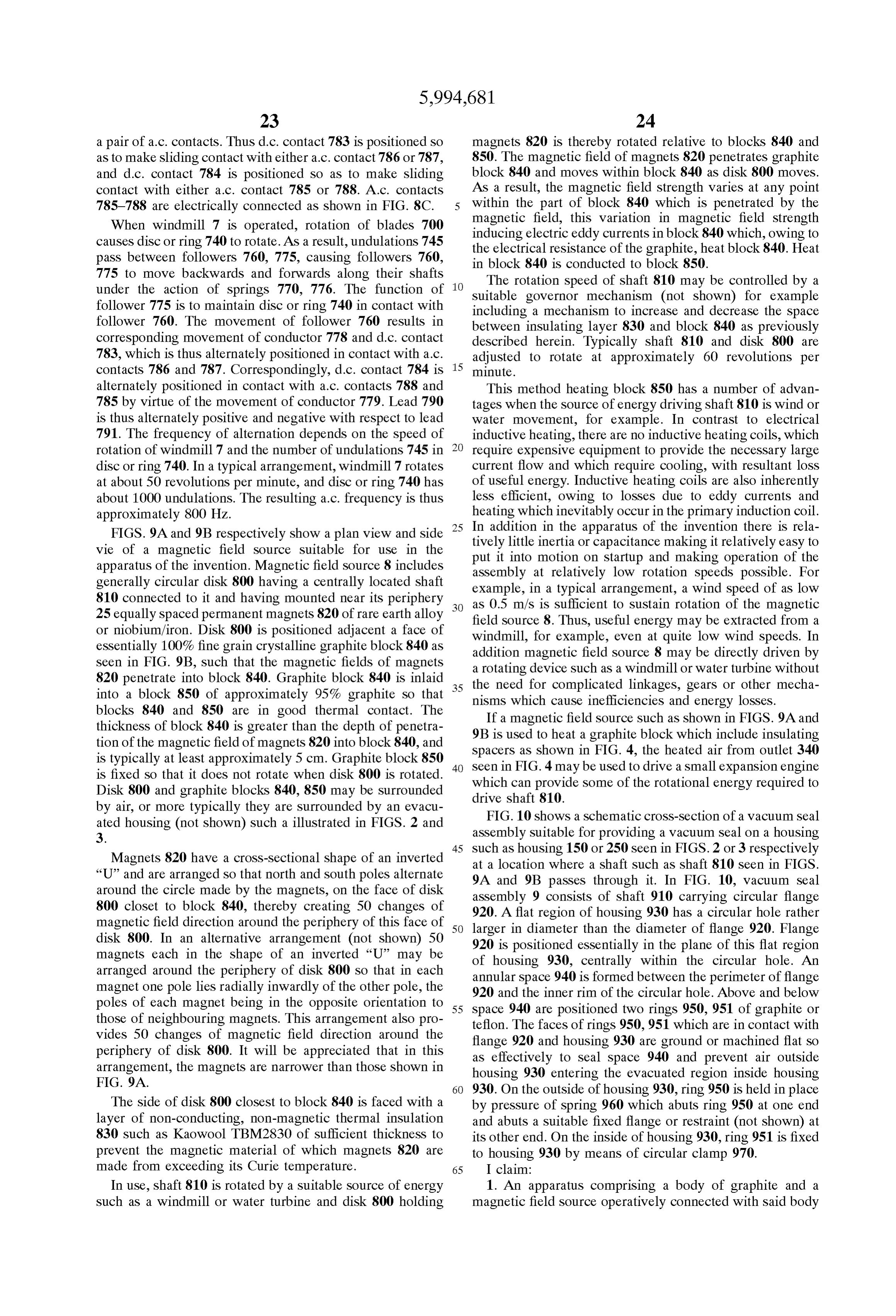
Page 27
of graphite So that a magnetic field of Said magnetic field 8. The apparatus of claim 7 wherein the surface of said Source penetrates at least a portion of a Surface of Said body disk opposable to Said region of the Surface of Said body of of graphite, at least Said portion of Said Surface comprising graphite is covered with a Substantially non-conductive crystalline graphite, and So that at least one of Said magnetic thermal insulator.
field Source and Said body of graphite is movable relative to is a9.ceramic
The apparatus of claim 8 wherein said thermal insulator insulator.
the other for movement of Said at least one of Said magnetic 10. The apparatus of claim 5, further comprising means field Source and Said body of graphite relative to the other to for adjusting a Space between cause Said magnetic field in Said Surface portion of Said body magnets and Said Surface ofSaidSaid assembly of a plurality of body of graphite in of graphite to vary, whereby to induce eddy currents in Said response to a rotation Speed of Said assembly magnets. body of graphite and heat Said body of graphite. 11. The apparatus of claim 1 which is housed in an 2. The apparatus of claim 1 further comprising heat evacuated housing.
insulation means operatively associated with Said body of 12. A method for heating a body of graphite comprising: graphite to reduce heat losses therefrom. providing a body of graphite and a magnetic field Source 3. The apparatus of claim 1 wherein Said magnetic field So that a magnetic field of Said magnetic field Source Source is movable relative to Said body of graphite and Said 15 penetrates at least a portion of a Surface of Said body of body of graphite is Substantially fixed. graphite, at least Said portion of Said Surface compris 4. The apparatus of claim 1 further comprising a windmill ing crystalline graphite; and or a turbine driven by flowing water, operatively associated moving at least one of Said magnetic field Source and Said with Said magnetic field Source to move Said magnetic field body of graphite relative to the other sufficiently to SOCC. induce eddy currents in Said body of graphite and 5. The apparatus of claim 4 wherein Said magnetic field thereby heat Said body of graphite. Source comprises an assembly of a plurality of magnets 13. The method of claim 12 comprising moving Said which are positioned adjacent Said portion of Said Surface of magnetic field Source relative to Said body of graphite. Said body of graphite, Said assembly being rotatable relative 14. The method of claim 12 comprising moving Said to Said body of graphite. 25 magnetic field Source by means of a windmill or a turbine 6. The apparatus of claim 5 wherein Said magnets are driven by flowing water.
positioned proximate the circumference of a circular disk 15. The method of claim 12 comprising positioning an having a Substantially centrally located rotatable shaft, a assembly of a plurality of magnets adjacent a region of the Surface of Said disk being opposable to Said portion of Said Surface of Said body of graphite and rotating Said assembly Surface of Said body of graphite, wherein when said Shaft is relative to Said body of graphite.
rotated Said magnets move relative to Said body of graphite. 16. The method of claim 15, further comprising adjusting 7. The apparatus of claim 6 wherein Said magnets have the a Space between Said assembly of a plurality of magnets and shape of an inverted “U” and wherein the poles of Said Said Surface of Said body of graphite in response to speed of magnets are positioned adjacent the Surface of Said disk Said rotating of Said assembly of magnets. opposable to Said portion of Said Surface of Said body of 35 graphite. k k k k k
Provenance
- Collection
- Cited prior art
- Original PDF
- patentimages.storage.googleapis.com →
- Filed
- 1998-02-04
- Pages
- 27
- Method
- pdftotext (the PDF's own text layer) + pdftoppm 300dpi page scans
- Source
- Google Patents bibliographic record
- Granted
- 1999-11-30
- Inventors
- Robert Lloyd; Larkden Pty Ltd
- Transcribed from
- patentimages.storage.googleapis.com →