patent · US5593640
Portable hydrogen generator
14 January 1997
Page 1 — bibliographic record
III USOO5593640A
IIHIIII
United States Patent (19) 11 Patent Number: 5,593,640 Long et al. (45) Date of Patent: Jan. 14, 1997 54). PORTABLE HYDROGEN GENERATOR "A Study of the Thermal Decomposition of Complex Metal
75 Inventors: Eugene Long, Boulder; Jeff Schmidt, 1230-1236.
Superior, Frank Lynch, Conifer, all of Ullmann's Encyclopedia of Indus. Chem., "Hydrides,” pp. Colo. 199-226, VCH, 1989.
"IV. Hydride-Symposium,” 7th & 8th May, 1987, Goslar 73) Assignee: Ball Corporation, Muncie, Ind. Langelsheim, Chemetall, GmbH. Inorganic Chemistry, V. 11, No. 6, 1972 A Study of the (21) Appl. No.: 476,729 Thermal Decomposition of Complex Metal Hydrides, by 22 Filed: Jun. 7, 1995 Dilts, et al.
Journal of Power Sources, 41 (1993)335-352 Design for the 511 Int. Cl. ............................................. B01, 7/02 cold start-up of a man-portable fuel cell and hydrogen 52 U.S. C. .......................... 422/111; 422/129; 423/657; storage system, by Ward, et al. 48/61 Ullmann's Encyclopedia of Industrial Chemistry, 5th Ed., 58 Field of Search ..................................... 422/129, 111, 1989, Hydrides, by Rittmeyer, et al. 422/239; 423/657; 48/61, 4, 197 R Chemetall GmBH, IV. Hydride-Symposium 7th and 8th May 1987, Goslar, Langelsheim.
56) References Cited Primary Examiner-Timothy McMahon
2,334,211 11/1943 Miller. 57) ABSTRACT
3,346,506 10/1967 Beumel. A hydrogen generator employs substantially adiabatic 3,734,863 5/1973 Beckert et al.. hydrolysis and thermal decomposition of chemical hydrides 3,862,052 1/1975 Beckert et al.. to provide a controllable generation of hydrogen from a 3,977,990 8/1976 Beckert et al. .. ... 423/648 small, lightweight container. The hydrogen generator 4,155,712 5/1979 Taschek .............. ... 422?239 includes a thermally isolated container for containing a 4,261,955 4/1981 Bailey, Jr. et al. .. ... 422/239 chemical hydride, a preheater to heat the chemical hydride 4,341,651 7/1982 Beckert et al. ...... ... 423/648 to a predetermined temperature before the chemical hydride 4,604,151 8/1986 Knowlton et al. ... 422/164 4,673,528 6/1987 Artz et al............. ... 423/648 is hydrolyzed, a water supply controlled to maintain sub 4,737,161 4/1988 Szydlowski et al. ... 48/61 stantially adiabatic and controlled generation of hydrogen 4,755,190 7/1988 Harris .......................................... 48/6 from said chemical hydride, and a buffer to supply an initial flow of hydrogen during generator start-up, absorb excess
OTHER PUBLICATIONS hydrogen during generator shut-down, and to smooth the "Design for the cold start-up of a man-portable fuel cell and hydrogen flow due to changing loads. hydrogen storage system,” J. of Power Sources, 41, 1993, pp. 335-357, Ward et al. 54 Claims, 4 Drawing Sheets
ydride
Page 2
Drawing sheet — no readable text.
Page 3
Drawing sheet — no readable text.
Page 4
Drawing sheet — no readable text.
Page 5
Drawing sheet — no readable text.
Page 6
PORTABLE HYDROGEN GENERATOR Thus, an improved hydrogen generator is needed which is lightweight, compact, portable, and temperature safe and
FIELD OF THE INVENTION which provides a controllable flow of hydrogen upon demand.
The present invention relates to a hydrogen generator, and more particularly to a lightweight, portable and nearly SUMMARY OF THE INVENTION adiabatic hydrogen generator and to a method for generating hydrogen. The present invention employs an adiabatic hydrolysis and thermal decomposition of a chemical hydride to provide
BACKGROUND OF THE INVENTION 10 a controllable generation of hydrogen from a small, light Hydrogen generators have long been used to generate weight, portable and hand handleable container. A preferred hydrogen hydrogen through the hydrolysis of chemical hydrides, and isolated container generator of the invention includes a thermally in particular, metal hydrides. For example, U.S. Pat. No. for containing a first chemical hydride; heating means for 2,334,211 discloses a hand-held generator containing cal 15 predetermined temperature; heating the first chemical hydride to a cium hydrides which, when submersed in water, produces a water supply for hydrolysis of sufficient hydrogen to fill an emergency signal balloon. the first chemical hydride only after the first chemical More recently, the most common portable source of hydro hydride reaches the predetermined temperature; a buffer, or gen is hydrogen bottles or tanks in which the hydrogen is tainer; and a control unit for controlling the from recovery device, for recovering hydrogen rate the con of genera stored under pressure. The hydrogen stored in these bottles 20 tion of hydrogen by the hydrogen generator. The buffer is or tanks is generated at a hydrogen production plant, shipped also used for hydrogen generation during startup and for as a cryogenic liquid, vaporized, and expanded into the tanks smoothing hydrogen production rates to follow demand or bottles under pressure. These hydrogen tanks or bottles variations.
are generally bulky and rather heavy. Further, when a tank or bottle is exhausted, it must be replaced with another tank 25 In preferred embodiments of the invention, the container or bottle. Storage tanks or bottles are utilized in field comprises a dewar having an outer shell and an inner vessel applications because, typically, hydrogen production facili defining an evacuated space therebetween, and having an ties have been considered too large, too heavy, too expensive insulating material positioned in the evacuated space, and in many instances, too unsafe, for portable operation. In wherein the first chemical hydride is placed within the inner response, there have been attempts to develop practical and 30 vessel. Preferably, the first chemical hydride is a metal portable hydrogen generators. hydride, and more preferably, a metal hydride having at least One such portable hydrogen generator, for example, is in themetal one taken from a group consisting of the metals found first three rows of the periodic chart. Such a metal disclosed in U.S. Pat. No. 4,155,712. U.S. Pat. No. 4,155, hydride can be a ternary composition, such as for example, 712 discloses a small portable hydrogen generator utilizing a metal hydride and water vapor in which hydrogen can be 35 a ternary composition consisting essentially of LiAlH4. automatically produced on demand or at a constant pressure Preferably, the heating unit heats the first chemical feed over widely varying hydrogen demand rates without hydride to a temperature greater than about 100 degrees C. water supply contamination or metal hydride caking com including,Such a heating unit can include a chemical composition, plications. Among the problems in the use of demand for example, a second chemical hydride posi responsive hydrogen generators, however, is that of a sudden tioned in the container between the first chemical hydride requirement made on the water vapor such that water instead and the water supply for generating an exothermic reaction of the water vapor could be drawn into direct contact with when the chemical composition is combined with water. As an alternative, or as a supplement to the chemical compo the fuel, thus causing a malfunction. U.S. Pat. No. 4,261,955 sition addresses this problem by utilizing a wall means for sepa heating unit, the heating unit may include an electrical rating adjacently disposed solid fuel and water compart 45 heater.
ments. The wall means includes two spaced apart porous The water supply includes a water source, a water pump hydrophobic membranes. During normal production of hydraulically coupled to the water source and electrically hydrogen gas, the membranes are of a character as to coupled to the control means, and a water conduit coupled normally only pass water vapor from the water supply to the between the water pump and the container. The water supply fuel compartment. If an abnormal demand is made on the 50 further includes an annular filter positioned in the container water vapor, it could inadvertently cause unvaporized water adjacent to an outlet of the water conduit. Still further, the to pass through one of the membranes. Therefore, a hydro second chemical hydride is a mixture of a compressible gen gas outlet is positioned between the spaced-apart mem porous medium and a chemical hydride positioned between branes to pull off the water before it could reach the metal the annular filter and the first chemical hydride. The mixture hydride fuel. 55 prevents caking and increase porosity of the second chemi Both U.S. Pat. Nos. 4,155.712 and 4,261,955 disclose cal hydride.
using compounds with a chemical hydride, such as lithium The hydrogen buffer includes an outlet conduit coupled to aluminum hydride (LiAlH4) in an attempt to control inter the container, a buffer chamber coupled to the outlet conduit, nally generated heat. Presently, however, no commercially and a rechargeable hydride positioned in the buffer chamber. viable small portable hydrogen generators are able to supply 60 The rechargeable hydride supplies hydrogen to the outlet hydrogen instantaneously and sustain a constant flow of conduit whenever the hydrogen demand exceeds the rate of hydrogen while controlling external structural heating and generation by the chemical hydrides. It also absorbs excess uncontrollably escalating temperatures and pressures in the hydrogen after the water supply has been stopped from generator due to uncontrolled hydrogen release by the supplying water to the container by the control unit. Pref chemical hydride. As a result, industry typically still uses 65 erably, the rechargeable hydride is a metal hydride. high pressure gas storage, metal hydride storage, or liquid The hydrogen generator further includes a control unit for hydrogen for a hydrogen gas supply. controlling an amount of hydrogen generated. The control
Page 7
unit includes a pressure switch coupled to the hydrogen primary chemical hydride 14, preferably a metal hydride, conduit, wherein the pressure switch senses a pressure of the such as, for example, lithium aluminum hydride (LiAlH4). hydrogen to generate a signal corresponding to the pressure Primary chemical hydride 14 undergoes both hydrolysis and of the hydrogen. The pressure switch is coupled to the water thermal decomposition reactions to generate hydrogen (H2). source to control a flow of water to the container based on 5 As used herein, hydrolysis is the exothermic chemical the pressure signal. Thus, the control unit controls the rate of reaction of a chemical hydride, such as LiAlH, with water hydrogen generation. to form oxides or hydroxides and hydrogen. Endothermic In preferred hydrogen generators, the chemical composi decomposition occurs in the chemical hydride when the heat tion generates sufficient heat to raise the temperature of the completes the reaction to form hydrogen and other byprod preferred LiAlH4 above about 100 degrees C. prior to the 10 luctS.
hydration of the LiAlH4. The chemical composition includes A heating unit 16 is positioned adjacent chemical hydride a second metal hydride, such as Cah, or other similar 14 and, when activated, heats primary chemical hydride 14 hydride, and a compressible porous medium, such as ver to a pre-determined temperature (preferably about 100 miculite. Such a chemical composition, through hydrolysis, degrees C. for LiAlH4). Activation of heating unit 16 avoids generates an exothermic reaction and exhibits stable hydro 15 chemical reactions associated with primary chemical gen generation characteristics while at a temperature below hydride 14 which can result in large water release, and, thus, about 590 degrees C. avoids an uncontrollable hydrogen release and an increase in Viewed in another way, the invention comprises a hydro pressure in container 26 during initial hydration of primary gen generator, including a container; a water source having 20 chemical hydride 14.
a water conduit for supplying water into the container; a first Water supply 18 supplies water into a water conduit 19, chemical hydride placed in the container; a chemical com which in turn is coupled to container 12. After primary position positioned in the container between the first chemi chemical hydride 14 reaches the predetermined temperature cal hydride and an outlet of the water conduit, the chemical (about 100 degrees C. for LiAlH4), the water from conduit composition being adapted to react with water supplied from 25 19 is converted to steam which permeates into primary the outlet of the water conduit to heat the first chemical chemical hydride 14, thereby hydrolyzing chemical hydride hydride, and delay hydration of the first chemical hydride 14 to generate hydrogen. The rate of hydrogen generation until it has reached a temperature sufficient to prevent the from primary chemical hydride 14 is determined, in primary first chemical hydride from undergoing an unstable exother part, by the rate that water is supplied to container 12 by mic reaction; and a buffer for recovering hydrogen from the 30 water supply 18.
container. In practicing the invention, it is important to avoid hydrat A preferred method of the invention includes the steps of ing primary chemical hydride 14 prior to the temperature of placing a first chemical hydride in a thermally isolated chemical hydride 14 reaching the predetermined tempera container; heating the first chemical hydride to a predeter ture. As more fully described below, this can be accom mined temperature, hydrolyzing the first chemical hydride 35 plished by either (1) preheating primary chemical hydride 14 only after the first chemical hydride reaches the predeter with a heater, such as an electric heater, prior to delivering mined temperature; recovering hydrogen from the container; water to container 12 in sufficient quantities to hydrolyze and controlling an amount of hydrogen generated by the primary chemical hydride 14, or (2) positioning a second hydrogen generator. The entire process balances the exo chemical hydride which is a mixture of compressible porous thermic chemical reaction with the endothermic decompo 40 medium and another chemical composition, which also sition in the first chemical hydride. serves as a chemical heater, between the water outlet of The invention, described briefly above in its various conduit 19 and primary chemical hydride 14 to generate heat embodiments, provides a lightweight, portable, and substan for heating the primary chemical hydride 14 to at least the tially adiabatic hydrogen generator. However, other features predetermined temperature, to prevent liquid water from and advantages of the invention may be determined from the 45 forming an unstable hydroxide or hydrating chemical drawings and detailed description of the invention that hydride 14, to convert the water in its liquid state to a water follows. vapor state, and to allow water vapor, i.e., steam, to hydro lyze primary chemical hydride 14 after the temperature of
BRIEF EDESCRIPTION OF THE DRAWINGS primary chemical hydride 14 reaches about 100 degrees C. 50 Thus, in practicing the invention, the large surge of hydro
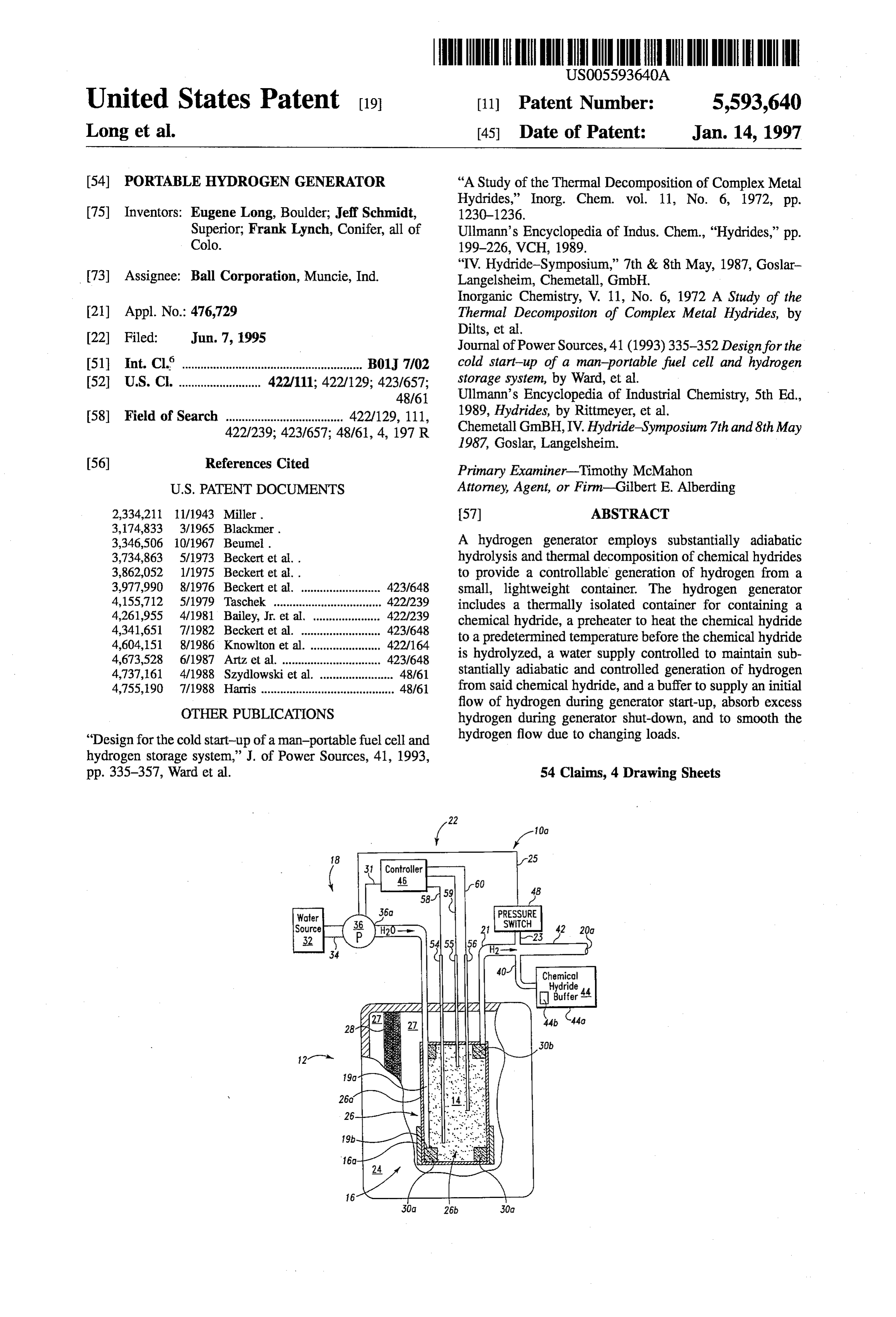
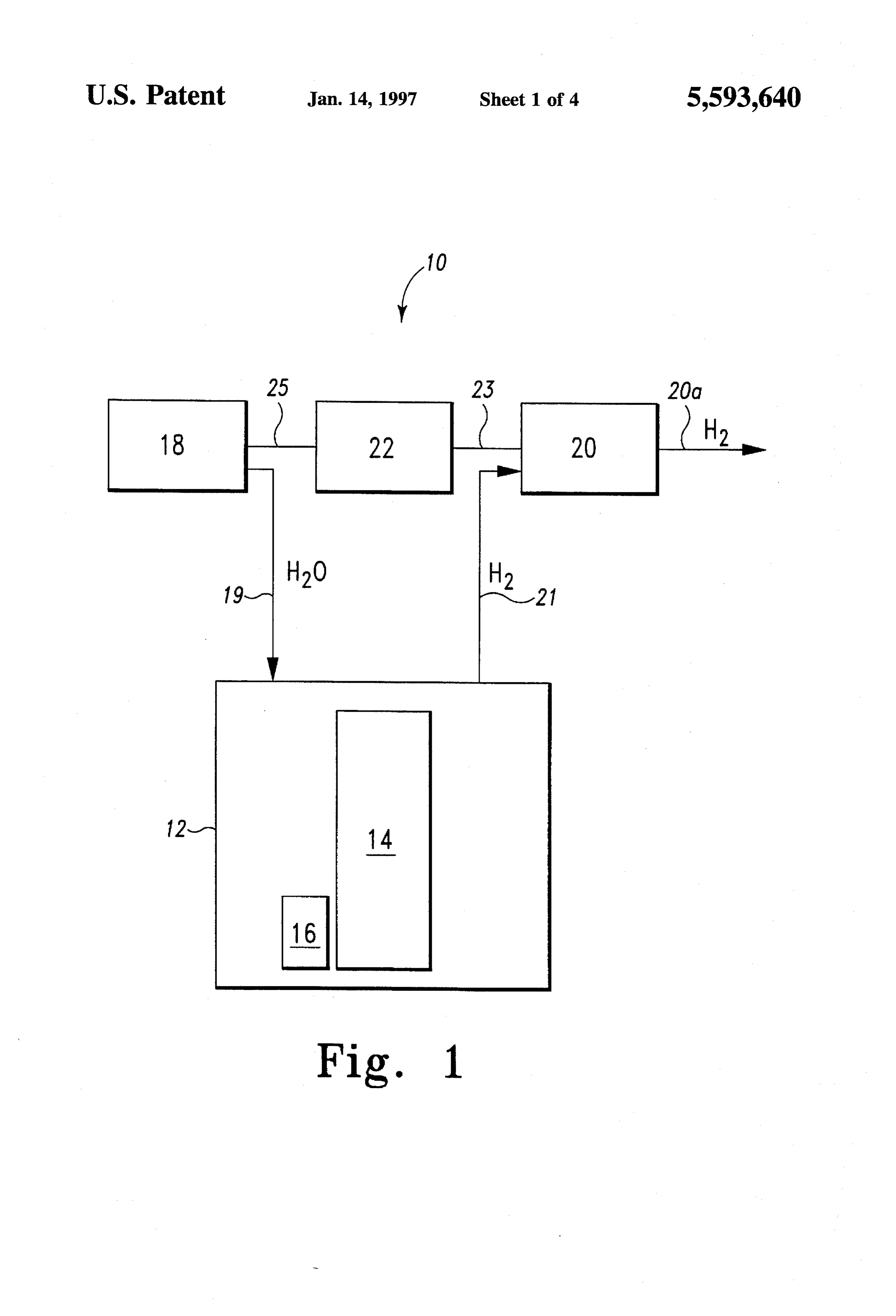
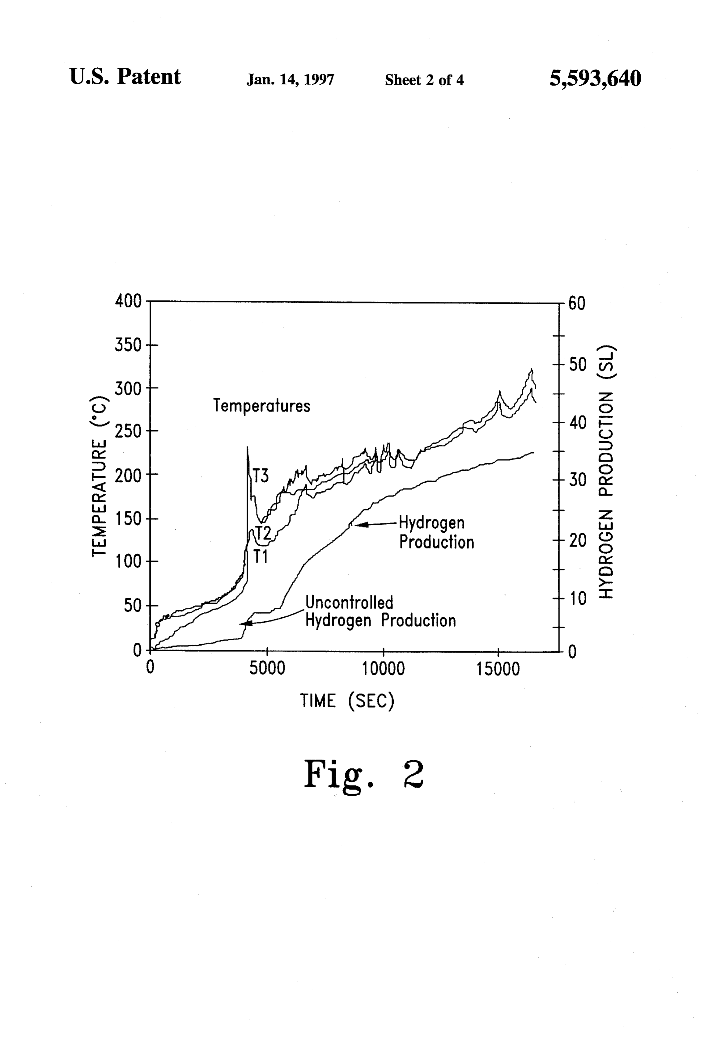
FIG. 1 shows a general block diagram of a hydrogen gen production typically associated with the start-up of a generator embodying the invention. hydrogen generator is avoided, thereby eliminating the need FIG. 2 shows a graph of hydrogen production during the for a large capacity hydrogen storage tank at the output of various hydrolysis and thermal decomposition stages of the hydrogen generator.
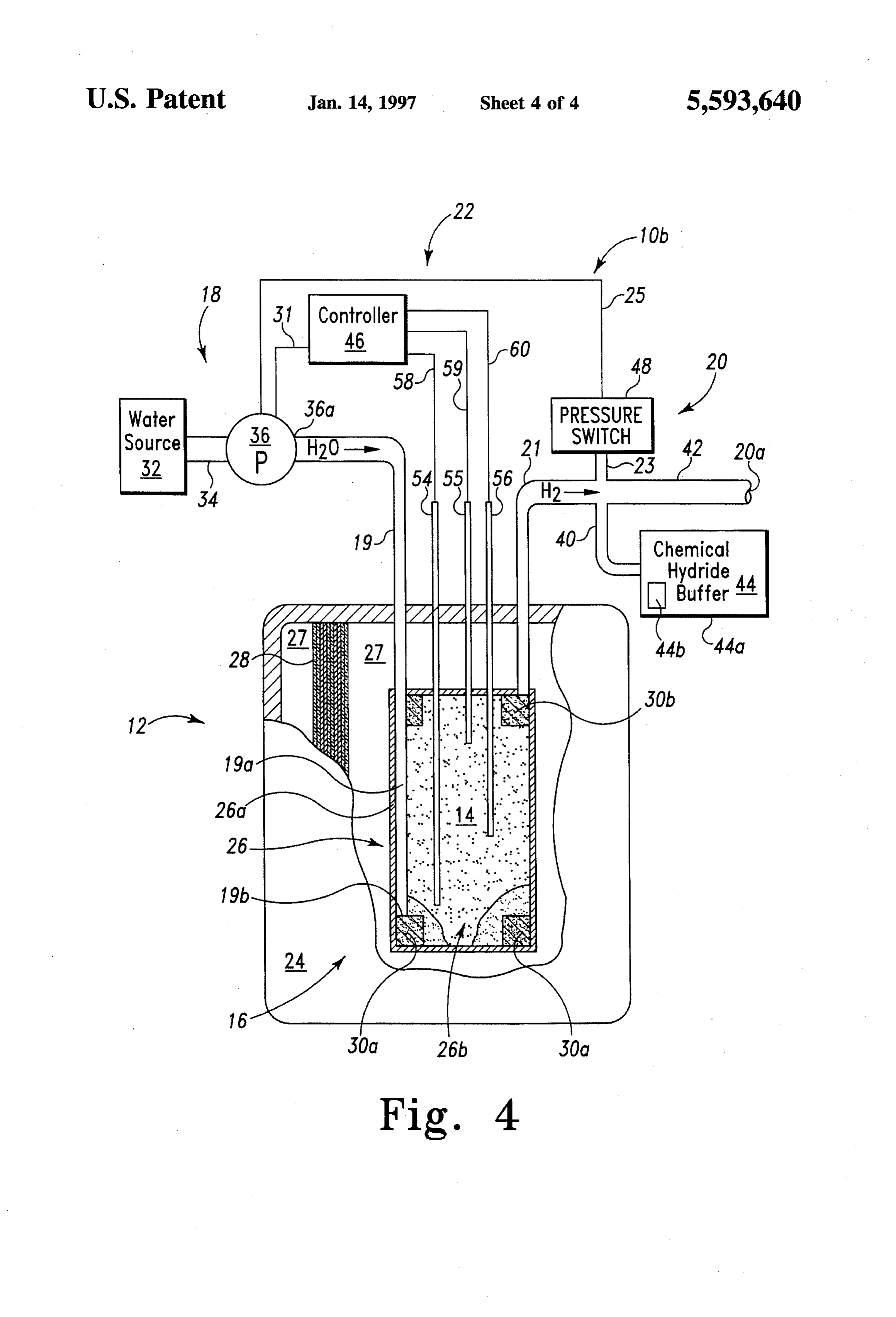
LiAlH4. 55 Abuffer 20 is coupled to container 12 via a conduit 21 for FIG. 3 shows a combined pictorial and block representa recovering the hydrogen generated inside container 12 dur tion of a first embodiment of the invention. ing the hydrolysis and thermal decomposition of primary FIG. 4 shows a combined pictorial and block representa chemical hydride 14. Buffer 20 includes an outlet 20a for tion of a second embodiment of the invention. supplying an output flow of hydrogen for use by a device 60 (not shown) such as, for example, a fuel cell, a space craft
DETALED DESCRIPTION OF THE thruster, a hydrogen burner, a storage vessel, etc. PREFERRED EMBODIMENTS Buffer 20 further serves to supply an initial flow of hydrogen to outlet 20a during the initial start-up of hydrogen
FIG. 1 shows a hydrogen generator 10 embodying the generator 10, as well as absorb excess hydrogen generated invention. Hydrogen generator 10 includes a thermally 65 after hydrogen generator 10 is commanded to stop generat isolated container 12, such as a vacuum insulated, multiple ing hydrogen. Preferably, buffer 20 contains a rechargeable wall dewar similar to a cryogenic dewar, containing a hydride buffer material, such as a metal hydride, which is
Page 8
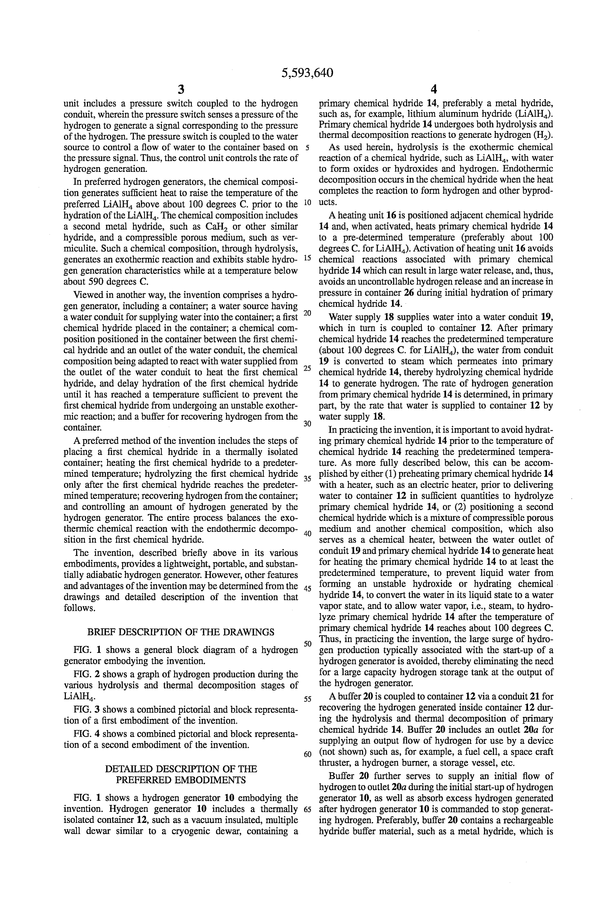
capable of supplying an initial flow of hydrogen upon start-up of hydrogen generator 10, and of absorbing excess TABLE I hydrogen generated when hydrogen generator 10 is com Hydride Thermal Decomposition manded to stop hydrogen production. By absorbing excess hydrogen during shut-down, buffer 20 reduces the hydrogen LiH 12.7 wo
pressure in container 12 from that which is typically asso AlH 10.1 who ciated with system shut-downs, thereby allowing the portion MgH2 7.7 wo of container 12 which contains primary chemical hydride 14 NaH 4.2 who to be made of lighter gauge materials. 10
A control unit 22 is provided for controlling an amount of The thermal decomposition of metal hydrides is generally hydrogen generated by hydrogen generator 10. Control unit less than 100% complete due to hydrogen solution in the 22 can be, for example, a pressure switch coupled to buffer metal phase. The definition of weight percent (w/o) used 20 via a conduit 23. Control unit 22 senses a hydrogen herein is the weight of hydrogen divided by the total weight pressure of container 12 and buffer 20, and generates there 15 ofAs the reactants, including hydrogen. shown in Table II, at low temperatures, in the presence from a control signal which is supplied, via a conductor 25, of excess water, all of the metal hydrides listed in Table I to water supply 18 to control the flow of water from water form hydroxides.
supply 18 to container 12, thereby controlling the hydrolysis of primary chemical hydride 14, and, thus, the flow of TABLE I hydrogen generated by primary chemical hydride 14 and 20 Error Reference source supplied to buffer 20. Although control unit 22 can be a not found. Excess Water Stored Product simple switch to control water supply 18 in an ON-OFF Reaction Water Water fashion, it is contemplated that control unit 22 can include a controller for receiving multiple pressure inputs and tem LiH + H2O -> LiOH + H. 7.5 wo 29.1 wo 25 LiAlH4 + 4H2O - LiAl(OH)4 + 4H. 7.3 who 21.2 who perature inputs which can be utilized to provide more AIH + 3H2O - Al(OH) + 3H 7.2 who 20.2 wo precise control over the flow of water supplied to container MgH2 + 2H2O -> Mg(OH)2 + 2H 6.3 wo 14.2 who 12. NaH + HO - LiOH + H. 4.7 who 8.8 wifo Preferred embodiments of the invention provide a signifi cant weight reduction over prior generators by eliminating 30 Table II shows the hydrogen generation capacities, via the need for a high pressure hydrogen storage tank to absorb excess water reactions in weight percent (w/o), of prime excess hydrogen production and supply hydrogen when candidate metal hydrides. In Table II, the "Stored Water” demand exceeds production, as well as by allowing the column includes the weight of the water shown on the left portion of container 12 which contains the primary chemical side of the reaction. The "Product Water' column excludes hydride to be made from lighter gauge materials due to the 35 water weight. Several of the hydroxide products listed in buffer characteristic of buffer 20. Preferred embodiments of Table II also form hydrates. Hydroxides and hydrates the invention also avoid the need for a heat rejection system decompose at elevated temperatures, thereby liberating by balancing the exothermic hydrolysis rate and the endot steam in the process. If the thermal decomposition of the hydroxides or hydrates occurs to generate HO in the hermic decomposition inside an isolated thermal container. presence of unreacted hydrides, an uncontrolled reaction In order for hydrogen generator 10 to remain an ultra proceeds with potentially dangerous results. The hydrogen lightweight unit, however, the primary chemical hydride 14 pressure which can be produced by these reactions is virtu must be based upon chemical hydrides which bind a rela ally unlimited. Thus, it is important to precisely control tively high percentage of hydrogen per unit weight. Prime water inventory in container 12 at all times. In addition, it is candidates for the primary chemical hydride 14 include 45 preferred to provide buffer capacity in buffer 20 to absorb chemical hydrides based upon one or more of the elements excess hydrogen to prevent excess hydrogen pressures in from the first three rows in the periodic chart, which include container 12, or alternatively provide relief valves to vent metals such as lithium, beryllium, magnesium and alumi the excess hydrogen to reduce the internal pressure of U. container 12.
Lithium, sodium and magnesium react directly with 50 Hydrides that are thermally stable and form hydroxides hydrogen, under commercially convenient pressures and upon reaction with excess water at room temperature temperature conditions, to form the binary metal hydrides become less stable and less prone to form hydroxides with LiH, NaH, and MgH Aluminum hydride (AlH) can be increasing temperature. Calcium hydride (Cah), for made directly at very high pressures, but it is usually formed example, reacts with water to form the hydroxide (Ca(OH)2) in solution. The latter method of forming AlH, however, 55 at room temperature. Above 400 degrees C., the product of results in solvent contamination that is objectionable for the water reaction is the oxide (CaO). Any hydroxide formed some applications, such as for use with fuel cells. below 400 degrees C. decomposes endothermically above The primary candidates for use with hydrogen generator 580 degrees C., liberating water. If there is any unreacted 10 as the primary chemical hydride 14 are the ternary hydride present when the water is released, it will react hydrides including commercially available LiAlH4, instantaneously producing H and CaO. The hydride itself NaAlH, LiBH and NABH. Other ternary hydrides, such decomposes thermally above 600 degrees C.
as Mg(AlH4) and liquid Al(BH), are also contemplated Magnesium hydride (MgH) is similar to Cah, forming for possible use with hydrogen generator 10. a hydroxide at lower temperatures. But, unlike Cah, MgH Table I shows the thermal decomposition capabilities of decomposes thermally at a lower temperature (280 degrees several candidate metal hydrides in order of weight percent 65 C.) than its hydroxide (350 degrees C.). Lithium hydroxide age (w/o) of hydrogen evolved, assuming complete thermal is stable to its melting point, 450 degrees C. Accordingly, decomposition. knowledge of the details of all reactions wherein hydrogen
Page 9
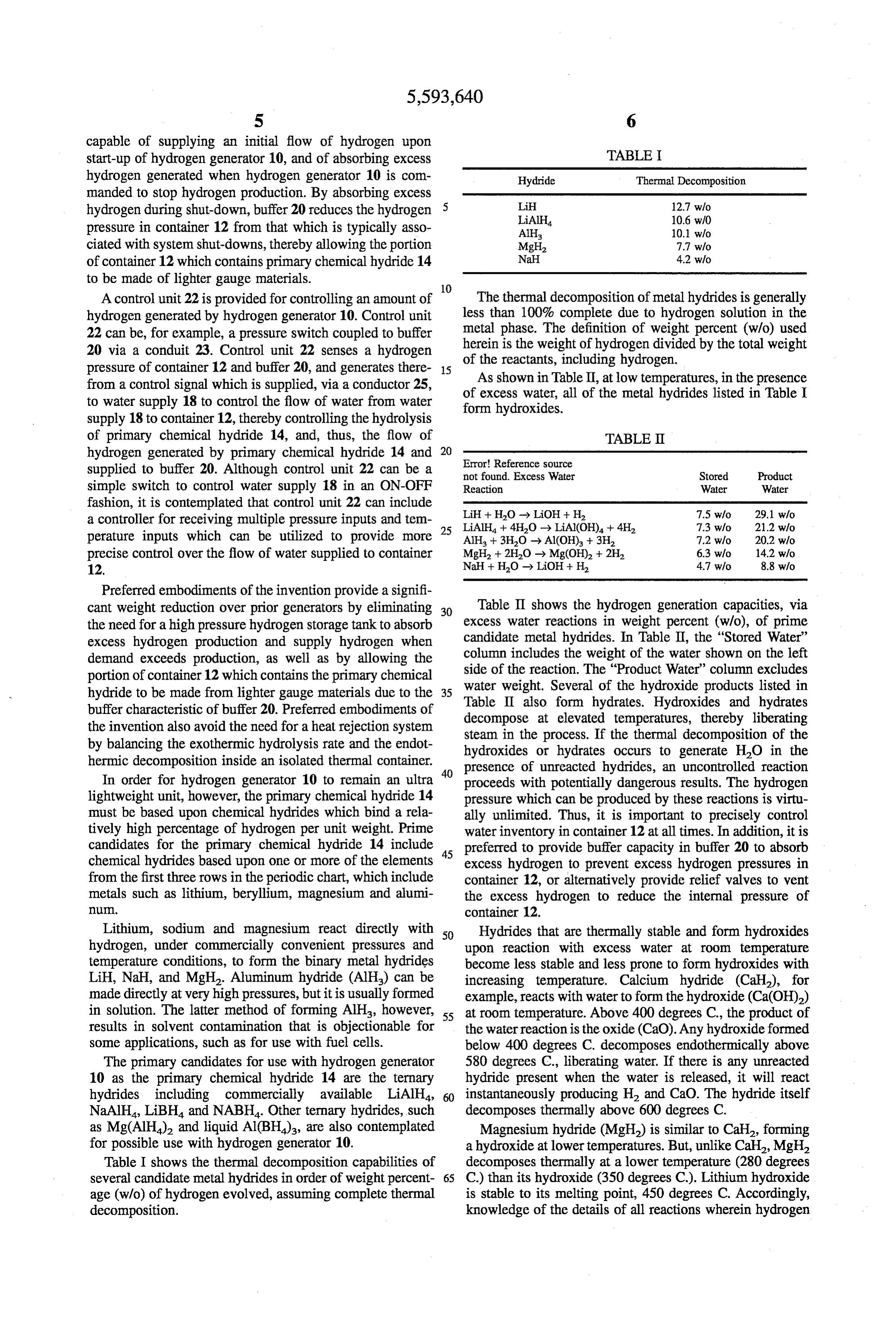
or water consumed or released is essential for the effective accompanied by uncontrolled temperature elevation. Thus, use of a chemical hydrogen generator. it is desired to avoid reaction Nos. (1) and (2) in Table III to The preferred chemical hydride for use with hydrogen avoid the problems associated with uncontrolled water generator 10 is lithium aluminum hydride (LiAlH4). LiAlH4 release. To avoid the reaction Nos. (1) followed by (2), the is a white microcrystalline powder that turns gray due to LiAlH4 chemical hydride 14 is heated by heating unit 16 to aluminum precipitates due to thermal decomposition. about 100 degrees C. prior to hydrolysis of the primary LiAlH4 also hydrolyzes slowly in air due to humidity. The chemical hydride 14 to generate hydrogen. hydrolysis and thermal decomposition chemistry of LiAlH4 The thermal isolation of container 12, preferably a provides an abundance of hydrogen per unit weight, and vacuum-insulated dewar similar to the dewars used to con LiAlH4 decomposes in a complex manner which can be O tain cryogens, allows the hydrogen generator 10 to be adiabatic to both conserve and use the heat generated above controlled with temperature and carefully metered water 100 degrees C. The heat above 115 degrees C. generated by addition. LiAlH4 reacts spontaneously and violently with exothermic liquid water, uncontrollably decomposing to give off hydro 3 of Table III)hydrolysis is used to reaction of the LiAlH4 (reaction No.
generate additional hydrogen by the gen gas and heat. endothermic thermal decomposition (reaction No. 4 of Table Table III shows all the known reactions of LiAlH, 5 III), which in turn lowers the temperature in container 12. including both hydrolysis (Hydro.) and thermal decompo Thus, by providing athermally isolated environment for the sition (Therm.), as defined above, for producing hydrogen hydrogen generator, and by controlling the supply of water and other byproducts. for hydrolysis and the temperature, the generation of hydro
gen is maintained stable and controllable through balancing
TABLE III exothermic and endothermic reactions of Table III. The
Approx. thermal isolation of dewar container 12 also prevents the Temperature Type of outer surface thereof from heating, thus allowing the system No. in degrees C. Reaction Reaction H/HO to be packaged without substantial thermal material expan 1 <100 LiAlH4 + 4H2O -> Hydro. 1.0 25 sions and contractions. By utilizing both exothermic and
LiAl(OH) + 4H + endothermic reactions in hydrogen generator 10, the typical Heat problems associated with volumetric expansion are avoided. 2 >100 LiAl(OH) + Heat -> Therlin. Thus, hydrogen generator 10 provides a light weight, por LiAlO + 2H2O table, and nearly adiabatic, constant volume hydrogen gen
Heat The hydrogen generator 10 of FIG. 1 will now be 4 100-150 3LiAlH + Heat -> Therm. described with reference to the preferred embodiments LiAlH + 2Al + shown in FIGS. 3 and 4. The preferred embodiments of
5 >150 LiAlH + 4HO --> Hydro. 1.5 FIGS. 3 and 4 identify hydrogen generator 10 of FIG. 1 as
hydrogen generators 10a and 10b, respectively. Hydrogen 6H + Heat generators 10a and 10b differ primarily in the manner in
6LiH + 2Al +3H, which primary chemical hydride 14 is heated and in the 7 >220 LiH + H2O --> Hydro. 10 timing for supplying water to the hydrogen generator LiOH + H2 + Heat through conduit 19. Therefore, to avoid undue repetition, 40 where possible, the common features of the two embodi
The hydrolysis chemistry of LiAlH4 divides into two ments will be discussed together using common element classes: efficient water and inefficient water, often referred to numbers, and structural differences will be identified as they as insufficient water and excessive water, respectively. Reac are discussed.
tion No. 3 of Table III shows, for example, the efficient As shown in FIGS. 3 and 4, container 12 comprises a (insufficient) water hydrolysis reaction. In the efficient water 45 thermally isolated dewar having an outer shell 24 and an hydrolysis reaction of equation 3, one mole of water pro inner vessel 26 which combine to define a vacuum space 27 duces two moles of hydrogen. Reaction Nos. 1 and 7 of therebetween. Thermal insulation 28 is positioned in Table III shows examples of the inefficient (excessive) water vacuum space 27 to form an annular insulating wall around hydrolysis reaction. The inefficient water reaction requires inner vessel 26. Vacuum space 27 may be filled with an one mole of water to generate one mole of hydrogen. 50 insulating material, such as fiberglass, multilayer material, Regardless of whether water is a limiting or excess reagent, or other insulating materials. the observed enthalpy, or heat of hydrolysis, in both the The generation of hydrogen by hydrogen generator 10 efficient and inefficient cases is approximately the same, and primarily occurs in inner vessel 26 of container 12, wherein is approximately 700 kJ/mole. the primary chemical hydride 14 (preferably LiAlH4) is In practicing the invention, the reactions set forth in 55 contained. Inner vessel 26 is preferably made from materi reactions (1) and (2) of Table III are avoided so that large als, such as stainless steel and the like, which can accom amounts of water and hydrogen are not released in an modate the positive pressures occurring therein during uncontrolled fashion. For example, FIG. 2 shows, during the hydrogen generation, as well as accommodate temperatures time period between 0 and 5000 seconds, the amount of which can exceed 300 degrees C. In operation, the primary hydrogen and heat generated in container 12 if preheating is 60 chemical hydride 14 is gradually heated and the hydrolysis not provided. As shown in FIG. 2, during this period, and thermal decomposition of primary chemical hydride 14 hydrogen generation and temperatures in container 12 results in a slow increase in temperature in inner vessel 26, increases dramatically at about 4000 seconds due to the as shown for example in FIG. 2 from 5000 to 15000 seconds. production of excess water which in turn reacts with avail Outer shell 24, however, remains substantially at ambient able LiAlH4 to release more hydrogen when the temperature 65 temperature due to the thermal isolation resulting from the of the LiAlH4 reaches about 100 degrees C. This results in vacuum 27 and the insulation 28 between inner vessel 26 an uncontrolled and excessive production of hydrogen and outer shell 24 of container 12. In turn, the thermal
Page 10
isolation of container 12 thermally isolates the primary The quantity of water supplied to inner vessel 26 is chemical hydride 14 from the ambient conditions external to metered so as to promote controllable and sustained container 12. Therefore, the heat generated during hydroly hydrolysis and thermal decomposition of primary chemical sis of primary chemical hydride 14 (see, for example, hydride 14 to generate hydrogen through the complementary reaction No. 3, Table III) is available to promote further exothermic and endothermic reactions identified, for thermal decomposition of primary chemical hydride 14 into example, as reaction Nos. (3)-(7) in Table III. The hydrogen hydrogen through induced thermal reactions (see reactions generated by the primary chemical hydride 14 migrates to Nos. 4 and 6, Table III). The thermal decomposition of the upper region of inner vessel 26, and flows through filter primary chemical hydride 14 is an endothermic reaction material 30b as the hydrogen exits inner vessel 26 via which absorbs at least a portion of the heat generated during 10 conduit 21 and is supplied to hydrogen buffer 20. hydrolysis of primary chemical hydride 14, thereby stabi As shown in FIG. 4, heating unit 16 comprises a chemical lizing the temperature inside inner vessel 26 below the heating composition 16b. (However, a supplemental elec temperature which would have resulted if no such endot trical heater 16a can be provided adjacent to sidewall 26a of hermic reaction occurred. As a result, hydrogen generator 10 inner vessel 26 to provide auxiliary heating capacity, if is maintained substantially adiabatic. needed.) During start-up of the hydrogen generator 10b As stated above, the preferred hydride for primary chemi 5 shown in FIG. 4, water supply 18 begins immediately to cal hydride 14 is a metal hydride having at least one metallic supply water to inner vessel 26 via water conduit 19. element taken from a group consisting of the metals found Controller 46 actuates, via conductor 31, pump 36 which in the first three rows of the periodic chart. In preferred provides a metered flow of water through conduit 19 into embodiments of the invention, this metal hydride is a ternary 20 inner vessel 26. Conduit 19 extends vertically to the lower composition, such as for example, lithium aluminum region of inner vessel 26 and supplies liquid water through hydride (LiAlH4). its output 19b to annular filter 30a. The water permeates Also contained in inner vessel 26 is a pair of annular filter 30a and is distributed to the outer surface of filter filters 30a and 30b. Filter 30a is positioned in a lower material 30a to begin hydrolysis of chemical heating com portion of inner vessel 26 and is used to filter HO, in the 25 position 16b. Preferably, heating composition 16b is a forms of either liquid or vapor, entering inner vessel 26. combination of a metal hydride, such as calcium hydride Annular filter 30a distributes the liquid or water vapor (CaF2 or other similar hydrides), and a compressible porous entering inner vessel 26 around the lower outer region of medium, such as vermiculite. Upon hydrolysis of the CaH2 inner vessel 26. Filter 30b is positioned in the upper region or other similar hydrides in heating composition 16b, Cah of inner vessel 26 for filtering the generated hydrogen which 30 or other similar hydrides undergo an exothermic hydrolysis has migrated to the top of inner vessel 26. to produce hydrogen and heat, and the heat produced thereby In FIGS. 3 and 4, heating unit 16 is positioned near a raises the temperature of the composition 16b, the supplied lower portion of inner vessel 26. As shown in FIG.3, heating water and the primary chemical hydride 14. After the unit 16 is an electric heater 16a, preferably a silicon heater, temperature of the chemical composition 16b reaches 100° positioned adjacent to an outer surface of inner vessel 26. 35 C., the supplied water is converted to water vapor which Electrical energy is supplied to electrical heater 16a by an then permeates through the second chemical hydride mix electrical source (not shown). During the initial start-up of ture 16b, to reach primary chemical hydride 14. The heated hydrogen generator 10a, electrical heater 16a supplies heat chemical hydride 14 is further heated by the steam and to the side-walls 26a of inner vessel 26, and accordingly, reacts, initially, according to the exothermic hydrolysis supplies heat to primary chemical hydride 14 (LiAlH4). 40 reaction of reaction No. 3 of Table III. After an amount of time sufficient for heater 16a to raise the Pump 36 meters the amount of water entering inner vessel temperature of primary chemical hydride 14 to about 100 26 so as to prevent to premature saturation of primary degrees C., then controller 46 supplies a signal to a pump 36 chemical hydride 14, and thereafter promotes a controlled of water supply 18 via conductor 31, and pump 36 responds and sustained reactions in primary chemical hydride 14 to by supplying a metered amount of water via conduit 19 to 45 generate hydrogen through complimentary exothermic and inner vessel 26. endothermic reactions of the reaction No. (3) through (7) Water supply 18 includes a water source 32 coupled via shown in Table III. Pump 36 may be effectually operated by a water conduit 34 to pump 36. Pump 36 is coupled at its a "bang-bang' controller, i.e. on-off, in response to the output 36a to conduit 19. Since chemical hydride 14 and internal pressure within inner vessel 26. The heat of vapor inner vessel 26 are at a temperature of about 100 degrees C., 50 ization of the supplied water and of the exothermic/endot when the water reaches a lower conduit portion 19a of hermic chemical conversations of the primary and secondary conduit 19, the liquid water is converted to water vapor or chemical hydrides counteract to provide a substantially steam, which then exits conduit outlet 19b, permeates annu adiabatic process without the generation of unacceptably lar filter 30a, and is in turn distributed annularly in a lower high temperatures within the inner vessel. inner region 26b of inner vessel 26. The steam then passes 55 The hydrogen generated by the heating composition 16b through primary chemical hybrid LiAlH4 to generate hydro and primary chemical hydride 14 migrates to the upper gen, initially, according to reaction No. 3 of Table III. region of inner vessel 26, and flows through filter material As an alternative to empirically determining the time 30b as the hydrogen exits inner vessel 26 via conduit 21 and required to heat primary chemical hybrid to the predeter is supplied to the hydrogen buffer 20. mined temperature, controller 46 can receive temperature Hydrogen buffer 20 shown in FIGS. 3 and 4 includes feedback signals from one or more of the thermocouples hydrogen conduits 40 and 42, and a rechargeable metal 54-56 via electrical conductors 58–60, respectively, which hydride buffer 44. Rechargeable hydride buffer 44 provides are positioned at various levels inside inner vessel 26. Thus, a receptacle 44a containing a buffer material 44b which once the temperature of chemical hydride 14 reaches the serves as a low pressure hydrogen storage medium capable predetermined, substantially uniform temperature, control 65 of both supplying hydrogen and absorbing hydrogen. Pref ler 46 generates a signal to activate pump 36 for starting erably, the buffer material 44b is a rare earth pentanickel water delivery to inner vessel 26. alloy, such as "Alloy M” sold by Hydrogen Consultants, Inc.
Page 11
of 12420 North Dumont Way, Littleton, Colo. or a pentan and inner vessel 26. As shown in FIGS. 3 and 4, thermo ickel alloy. The amount of rechargeable hydride needed couples 54, 55 and 56 are arranged to sense the temperatures varies according to the size and duty cycle of the prescribed at the lower, upper and mid regions, respectively, of primary load. chemical hydride 14 in inner vessel 26. Thermocouples 54, Rechargeable hydride buffer 44 provides efficient start-up 5 55 and 56 are electrically coupled to controller 46 via and shut-down of hydrogen generator 10 by generating the electrical conductors 58, 59 and 60, respectively. From the initial flow of hydrogen during start-up and absorbing excess thermocouple outputs of thermocouples 54-56, controller 46 hydrogen generated during shut-down. It also buffers varia generates a temperature display which is readable by a tion in the hydrogen demand during operation. human observer. Alternatively, or in addition to the tem Upon initial start-up of hydrogen generator 10a and 10b 1 operature display, controller 46 uses the temperature feedback signals received from thermocouples 54-56 to generate a shown in FIGS. 3 and 4, buffer material 44b of rechargeable signal which is supplied to pump 36 via electrical conductor metal hydride buffer 44 generates an initial output of hydro 31 to control or stop pump 36 from supplying water to inner gen which is supplied to outlet. During this time, primary chemical hydride 14 is being heated by heating unit 16 (i.e., vessel maximum 26, if a temperature in inner vessel 26 exceeds a acceptable value, such as for example, 300 the electrical heater 16a of hydrogen generator 10a, or the 15 degrees C., or has not yet reached an acceptable temperature, chemical heating composition 16b of hydrogen generator such as for example 100° C. as explained above. 10b) to the predetermined temperature of about 100 degrees
C. In hydrogen generator 10b of FIG. 4, however, hydrogen The invention described in the various preferred embodi generation begins in inner vessel 26 by the hydrolysis of ments above provides a lightweight and portable hydrogen heating composition 16b. Thus, in hydrogen generator 10b 20 generator which is substantially adiabatic. The inner con of FIG. 4, rechargeable metal hydride buffer material 44b tainer 26 is temperature controlled while the outer container and heating composition 16b both contribute hydrogen for 12 remains at ambient temperature. Although the invention meeting the initial flow requirements of a device coupled to has been described in terms of preferred embodiments, outlet 20a. After primary chemical hydride 14 reaches a workers skilled in the art will recognize that changes may be temperature of 100 degrees C., the primary chemical hydride made inform and in detail without departing from the spirit is hydrolyzed with steam which is formed in conduit 19, and 25 andWhatscope of the following claims. is claimed is:
the primary chemical hydride 14 becomes the major con 1. A hydrogen generator, comprising: tributor to the total output of hydrogen from hydrogen generators 10a and 10b. a thermally isolated container, During shut-down of hydrogen generators 10a and 10b a first chemical hydride placed in said thermally isolated shown in FIGS. 3 and 4, controller 46 commands pump 36 30 container, to cease water delivery to inner vessel 26; however, hydro heating means for heating said first chemical hydride to a gen continues to be generated in inner vessel 26 until the predetermined temperature; water contained therein is depleted. During this shut-down a water supply for hydrolysis of said first chemical phase of hydrogen generator 10, excess hydrogen generated hydride only after said first chemical hydride reaches prior to water depletion in inner vessel 26 is absorbed by the 35 said predetermined temperature; buffer metal hydride 44b in rechargeable hydride buffer 44. buffer means for recovering hydrogen from said con Buffer 44 also serves to smooth hydrogen demand swings tainer, and during normal operation.
After initial start-up, the amount of hydrogen production control means for controlling the rate of hydrogen gen generated by hydrogen generators 10a, 10b is dependent 40 eration by said hydrogen generator. upon the amount of water which is introduced into inner 2. The hydrogen source of claim 1, wherein said thermally vessel 26, and thus, hydrogen flow from outlet 20a increases isolated container comprises a dewar having an outer shell in relation to the amount of water which is supplied to inner and an inner vessel defining a vacuum space therebetween, vessel 26. As the amount of hydrogen generated in inner and having thermal insulation positioned in said vacuum space.
vessel 26 increases, the hydrogen pressure increases in inner 45 3. The hydrogen generator of claim 1, wherein said first vessel 26, as well as conduits 21, 23, 40 and 42, and in chemical hydride comprises a metal hydride. rechargeable metal hydride buffer 44. To control the hydro 4. The hydrogen generator of claim3, wherein said metal gen generation and pressure, control unit 22 includes a hydride comprises at least one metal taken from a group pressure switch 48 to sense the hydrogen pressure in hydro consisting of the metals found in the first three rows of the gen conduit 40 and to generate a signal to reduce or cutoff 50 periodic chart.
the flow of water provided by pump 36. As shown in FIGS. 5. The hydrogen generator of claim 4, wherein said metal 3 and 4, pressure switch 48 is coupled to hydrogen conduit hydride is a ternary composition. 21 via hydrogen conduit 23. Thus, pressure switch 48 senses 6. The hydrogen generator of claim 5, wherein said the hydrogen pressure in conduit 21, which is coupled to ternary composition consists essentially of LiAlH4. inner vessel 26, and when the sensed pressure reaches the 55 7. The hydrogen generator of claim 6, wherein said predetermined trigger point of pressure switch 48, pressure heating means heats said LiAlH4 to a temperature greater switch 48 generates a stop signal which is supplied to pump than about 100 degrees C.
36 via electrical conductor 25. Pump 36 responds by stop 8. The hydrogen generator of claim 1, wherein said ping the flow of water to inner vessel 26. When the pressure heating means comprises a second chemical hydride posi sensed by pressure switch 48 decreases below the trigger 60 tioned in said container between said first chemical hydride point, pressure switch supplies a run signal to pump 36, and and said water source for generating an exothermic reaction pump 36 responds by metering additional water to inner when said second chemical hydride is combined with water. vessel 26 for hydrolysis of the primary chemical hydride 14. 9. The hydrogen generator of claim 8, wherein said Thus, pressure switch 48 cycles pump 36 ON and OFF in second chemical hydride comprises a metal hydride. relation to the hydrogen pressure in inner vessel 26. 65 10. The hydrogen generator of claim.9, wherein said metal In some applications, it is desirable to know the tempera hydride consists essentially of Cah or other similar ture at various levels within the primary chemical hydride 14 hydrides.
Page 12
11. The hydrogen generator of claim 1, wherein said 21. The hydrogen generator of claim 19, wherein said first heating means comprises an electrical heater. chemical hydride comprises a metal hydride. 12. The hydrogen generator of claim 1, wherein said water 22. The hydrogen generator of claim 21, wherein said supply comprises: metal hydride comprises at least one metal taken from a a water source; group consisting of the metals found in the first three rows a water pump hydraulically coupled to said water source of the periodic chart.
and electrically coupled to said control means; and 23. The hydrogen generator of claim 22, wherein said a water conduit coupled between said water pump and metal hydride comprises a ternary composition. said container. 24. The hydrogen generator of claim 23, wherein said 13. The hydrogen generator of claim 12, wherein said 10 ternary composition consists essentially of LiAlH4. water source further comprises an annular filter positioned in 25. The hydrogen generator of claim 19, wherein said said container adjacent an outlet of said water conduit. chemical composition generates sufficient heat to raise the 14. The hydrogen generator of claim 13, wherein said temperature of said LiAlH4 above about 100 degrees C. second chemical hydride further comprises a compressible prior to the hydrolysis of said LiAlH4.
porous medium positioned between said annular filter and 15 26. The hydrogen generator of claim 19, wherein said said first chemical hydride to prevent liquid water from mixture of components of said chemical composition com hydrating said first chemical hydride while a temperature of prise:
said first chemical hydride is below said predetermined a second chemical hydride; and temperature. a compressible porous medium. 15. The hydrogen generator of claim 1, wherein said 20 27. The hydrogen generator of claim 26, wherein said buffer means comprises: second chemical hydride, when hydrolyzed, generates an an outlet conduit coupled to said container, exothermic reaction and exhibits stable hydrogen generation a buffer chamber coupled to said outlet conduit; and characteristics while at a temperature below about 590 a rechargeable hydride positioned in said buffer chamber. 25 degrees C.
16. The hydrogen generator of claim 15, wherein said 28. The hydrogen generator of claim 26, wherein said rechargeable hydride supplies hydrogen to said outlet con second chemical hydride comprises a metal hydride. duit when said first chemical hydride is being heated by said 29. The hydrogen generator of claim 28, wherein said heating means, and absorbs excess hydrogen after said chemical hydride consists essentially of Cah or other hydrolysis is stopped by said control means from hydrolyz 30 similar hydride.
ing said first chemical hydride. 30. The hydrogen generator of claim 26, wherein said 17. The hydrogen generator of claim 16, wherein said compressible porous medium comprises vermiculite. rechargeable hydride comprises a metal hydride. 31. The hydrogen generator of claim 19, wherein said 18. The hydrogen generator of claim 1, wherein said recovery means comprises:
control means comprises a pressure switch coupled to said 35 a hydrogen conduit coupled to said container; container for sensing a hydrogen pressure in said container, a buffer chamber coupled to said hydrogen conduit; and and for generating a signal corresponding to said hydrogen a rechargeable hydride positioned in said buffer chamber. pressure, said pressure switch being electrically coupled to 32. The hydrogen generator of claim 31, wherein said said water supply for supplying control signals thereto. rechargeable hydride comprises a metal hydride. 19. A hydrogen generator, comprising: 40 33. The hydrogen generator of claim 31, wherein said a thermally isolated container; rechargeable hydride supplies hydrogen to said hydrogen a water source having a water conduit for supplying water conduit when said first chemical hydride is being heated by into said container; said chemical composition, and absorbs excess hydrogen a first chemical hydride placed in said container; generated after said water source is stopped from supplying 45 water to said container.
a control for operation of said water source; 34. The hydrogen generator of claim 19, wherein said a chemical composition positioned in said container control means comprises a pressure switch coupled to said between said first chemical hydride and an outlet of hydrogen conduit, said pressure switch sensing a pressure of said water conduit, said chemical composition includ said hydrogen to generate a signal corresponding to said ing components to react exothermically with water 50 pressure of said hydrogen, and said pressure switch being supplied into said container to heat said first chemical coupled to said water source to control a flow of water to hydride, said container based on said pressure signal. said control operating said water source to supply water to 35. A hydrogen generator, comprising: said container, prior to hydrolysis of said first chemical hydride, to generate within said container a temperature 55 aa thermally first isolated container, chemical hydride placed in said container;
sufficient to prevent said first chemical hydride from forming unstable products when said first chemical a water supply for hydrolysis of said first chemical hydride is hydrolyzed and thereafter at a rate to main hydride, said water supply including a water source for tain an adiabatic generation of hydrogen by said first supplying water into said container via a water conduit; chemical hydride; and 60 a hydrogen conduit coupled to said container for supply recovery means for recovering hydrogen from said con ing a flow of hydrogen from said container; tainer. control means for controlling the supply of water to said 20. The hydrogen source of claim 19, wherein said container to obtain an adiabatic generation of hydrogen thermally isolated container comprises a dewar having an from said first chemical hydride; and outer shell and an inner vessel defining a vacuum space 65 buffer means coupled to said hydrogen conduit, said therebetween, and having a thermal insulating material buffer means containing a rechargeable hydride for positioned in said vacuum space. generating hydrogen upon initial start-up of said hydro
Page 13
gen generator, and for absorbing excess hydrogen gen control means for controlling said water pump and the erated after said water source is stopped from supplying generation of hydrogen; and water into said container containing said first chemical buffer means coupled to said inner vessel, said buffer hydride. means containing a rechargeable hydride for generating 36. The hydrogen generator of claim35, wherein said first hydrogen prior to the temperature of said first chemical chemical hydride comprises at least one metal taken from a hydride reaching said predetermined temperature, for group consisting of the metals found in the first three rows absorbing excess hydrogen after said water pump is of the periodic chart. stopped from supplying water to said container, and for 37. The hydrogen generator of claim 35, wherein said first smoothing the hydrogen flow due to changing load chemical hydride consists of LiAlH4. 10 demands.
38. The hydrogen generator of claim 35, wherein said buffer means comprises a receptacle containing said 46. The hydrogen generator of claim 45, wherein said first rechargeable hydride. chemical hydride comprises at least one metal taken from a 39. The hydrogen generator of claim 38, wherein said group consisting of the metals found in the first three rows rechargeable hydride comprises a metal hydride. 15 of the periodic chart.
40. The hydrogen generator of claim 35, further compris 47. The hydrogen generator of claim 46, wherein said first ing preheating means to preheat the first chemical hydride to chemical hydride consists of LiAlH4. a predetermined acceptable temperature prior to hydrolysis 48. The hydrogen generator of claim 47, wherein said of said first chemical hydride. heating means comprises a chemical composition positioned 41. The hydrogen generator of claim 40 wherein said 20 in said inner vessel between said first chemical hydride and preheating means comprises a chemical composition posi an outlet of said water conduit, said chemical composition tioned in said container between said first chemical hydride including components to react exothermically with water and an outlet of said water conduit, said chemical compo supplied into said inner vessel to heat said first chemical sition including components to react with water supplied to hydride, said container to heat said first chemical hydride, and to 25 said control operating said water pump to deliver an initial delay the flow of water to said first chemical hydride until supply of water to said inner vessel prior to the hydroly the first chemical hydride has reached a predetermined temperature sufficient to prevent said first chemical hydride sis of said first chemical hydride to generate within said from undergoing an unstable exothermic reaction when said inner vessel a temperature sufficient to prevent said first first chemical hydride is hydrolyzed. 30 chemical hydride from forming an unstable product 42. The hydrogen generator of claim 41, wherein said when said first chemical hydride is hydrolyzed. chemical composition comprises a metal hydride. 49. The hydrogen generator of claim 48, wherein said 43. The hydrogen generator of claim 40, wherein said chemical composition components comprise a metal hydride metal hydride consists essentially of Cah or other similar and vermiculite.
hydrides. 35 50. The hydrogen generator of claim 49, wherein said 44. The hydrogen generator of claim 35, further compris metal hydride consists essentially of Cah or other similar ing an electrical heater coupled to said container for heating hydrides.
said first chemical hydride to a predetermined temperature 51. The hydrogen generator of claim 45, wherein said prior to hydrolysis of said first chemical hydride. heating means includes a chemical compound having a 45. A small, lightweight, controllable hydrogen generator, 40 chemical component providing an exothermic reaction with comprising: water, wherein said compound includes a mixture of com a container forming a dewar having an outer shell and an pressible porous medium and chemical hydrides positioned inner vessel defining a vacuum space therebetween, between an outlet of said water conduit and said first and having thermal insulating material positioned in chemical hydride to prevent liquid water from forming
undesirable products in said first chemical hydride while a a first chemical hydride placed in said inner vessel; temperature of said first chemical hydride is below said heating means for heating said first chemical hydride to a predetermined temperature.
predetermined temperature sufficient to prevent said 52. The hydrogen generator of claim 45, wherein said first chemical hydride from undergoing unstable reac 50 heating means comprises an electrical heater. tions when hydrolyzed; 53. The hydrogen generator of claim 45, wherein said a water supply for hydrolysis of said first chemical buffer means comprises a receptacle coupled to said hydro hydride only after a temperature of said first chemical gen conduit, wherein said receptacle contains said recharge hydride reaches said predetermined temperature, said able hydride.
water supply including a water pump for supplying 55 54. The hydrogen generator of claim 45, wherein said water into said inner vessel via a water conduit; rechargeable hydride comprises a metal hydride. a hydrogen conduit coupled to said inner vessel for supplying a flow of hydrogen from said inner vessel; ck k k :
Provenance
- Collection
- Cited prior art
- Original PDF
- patentimages.storage.googleapis.com →
- Filed
- 1995-06-07
- Pages
- 13
- Method
- pdftotext (the PDF's own text layer) + pdftoppm 300dpi page scans
- Source
- Google Patents bibliographic record
- Granted
- 1997-01-14
- Inventors
- Eugene Long; Jeff Schmidt; Frank Lynch; Ball Corp
- Transcribed from
- patentimages.storage.googleapis.com →