patent · US5860414
Trough-shaped collector
19 January 1999
Page 1 — bibliographic record
United States Patent (19) 11 Patent Number: 5,860,414 Steinmann (45) Date of Patent: Jan. 19, 1999 54 TROUGH-SHAPED COLLECTOR 4,680,090 7/1987 Lew ........................................ 126/651
75 Inventor: Wolf-Dieter Steinmann, Sindelfingen, 5,465,708 11/1995 Goebel et al.. Germany 5,505,917 4/1996 Collier, Jr. .............................. 126/694
FOREIGN PATENT DOCUMENTS
73 Assignee: Deutsche Forschungsanstalt fuer
Luft- und Raumfahrt e.V., Bonn, 84971 3/1977 Australia ............................... 126/651 Germany 003405476 8/1985 Germany ............................... 126/651
21 Appl. No.: 807,265 25 36 800 4/1996 Germany. 001.453125 1/1989 U.S.S.R. ................................ 126/651
Primary Examiner-Carl D. Price 30 Foreign Application Priority Data Attorney, Agent, or Firm-Barry R. Lipsitz; Ralph F. Mar. 2, 1996 DEI Germany ........................ 196 08 138.6
Hoppin
(51) Int. Cl. ................................................... F24J 2/10 52 U.S. Cl. ........................... 126/657; 126/692; 126/701 In order to provide a trough-Shaped collector for radiation, 58 Field of Search ..................................... 126/657, 652, in particular for Solar radiation, comprising a trough-shaped 126/651, 654, 692, 693, 694, 695, 701, mirror extending in longitudinal direction and reflecting the 691, 678, 679, 683, 684, 698; 165/DIG. 109, radiation into a focus region, and an absorber line extending DIG. 110, DIG. 111, DIG. 113, DIG. 114 in longitudinal direction through the focus region of the trough-shaped mirror and having a guide tube for the heat 56) References Cited transport medium and an absorber pipe Surrounding the
guide tube and absorber line, with which the problems 4,094,299 6/1978 Voelker ................................... 126/674 existing as a result of the uneven irradiation of the absorber 4,134,393 1/1979 Stark et al.. line are also reduced or eliminated, it is Suggested that an 4,143,643 3/1979 Gerin et al.. annular passage medium flow in the annular chamber and 4,249,516 2/1981 Stark. that the annular passage medium couple the guide tube 4,289,118 9/1981 Stark. thermally to the absorber pipe.
4,520,794 6/1985 Stark et al.. 17 Claims, 5 Drawing Sheets
Page 2
Drawing sheet — no readable text.
Page 3
Drawing sheet — no readable text.
Page 4
Drawing sheet — no readable text.
Page 5
Drawing sheet — no readable text.
Page 6
Drawing sheet — no readable text.
Page 7
TROUGH-SHAPED COLLECTOR pipe and guide tube, which are mechanically uncoupled, is achieved and there is the possibility of influencing the
BACKGROUND OF THE INVENTION thermal coupling via the pressure, to which the annular The invention relates to a trough-shaped collector for passage medium is Subject, and the Velocity, with which the radiation, in particular for Solar radiation, comprising a annular passage medium flows. The flowing annular passage trough-shaped mirror which extends in longitudinal direc medium Sees to it that differences in temperature are com tion and reflects the radiation into a focus region and an pensated and thus the guide tube is evenly heated in its circumferential direction.
absorber line which extends in longitudinal direction through the focus region of the trough-shaped mirror and has This means that the wear and tear on the guide tube and a guide tube for the heat transport medium and an absorber the absorber pipe is diminished. The System also reacts more pipe Surrounding the guide tube Such that an annular cham quickly to control interventions since the guide tube has a ber is formed between guide tube and absorber pipe. smaller diameter than the absorber pipe and thus the flow Trough-shaped collectors of this type are known from the Velocity for the heat transport medium is higher in relation State of the art. to a pipe with a greater diameter when the mass flow rate is 15 the same.
In a known trough-shaped collector, the absorber line is The annular passage medium has, in addition, a buffer preferably formed by a pipe which is arranged in the focus effect So that the influence of Short-term operational region of the trough-shaped mirror. As a result of its variations, construction, the trough-Shaped mirror does not have an on the heatSuch as, for example, cloud covering of the Sun, transport medium is reduced.
ideal focal line but rather a focus region which can have an extension of approximately 1% of the mirror diameter. Since The pressure, to which the annular passage medium is the aim is to have a large mirror aperture and thus a large Subject in the annular chamber, is preferably Selected Such mirror diameter for the trough-shaped mirror, it is necessary that the annular passage medium is present in the fluid State for the pipe to have a large diameter in order to cover the at the maximum temperature which can be attained. The entire focus region as absorber. In this respect, absorber 25 resulting Single-phase flow of a fluid in the annular chamber pipes, the diameter of which can be in the order of magni provides for an optimum heat coupling of the absorber pipe tude of 10 cm, are required for a trough-shaped mirror which to the guide tube.
has, for example, a diameter of 10 m. In addition, the mechanical stability of the device is AS a result of the radiation reflected from the trough increased since the fluid flowing in the annular passage shaped mirror into the focus region, the pipe is heated decreases the thermal load on the absorber pipe and unevenly in circumferential direction. Due to the thermal increases its flexibility.
load, mechanical problems result with respect to pressure The absorber screen could be part of the absorber pipe so resistance and rigidity of the pipe, in particular, when the that the material resources are reduced. pipe has a large diameter. The transfer of heat from the absorber pipe to the heat Furthermore, the pipe bends out of its optimum position 35 transport medium flowing in the guide tube is particularly in the focus region and So an optimum irradiation of the efficient when the mass flow rate of annular passage medium absorber line is no longer ensured and the degree of effi through the annular chamber is greater than the mass flow ciency of the trough-shaped collector deteriorates. rate of heat transport medium through the guide tube. In the case of the trough-shaped collector according to DE 40 It is, in particular, expedient when the annular passage 43 31 784, the heat transport medium is guided in a guide medium is conveyed in a circuit So that only slight losses of tube within the absorber line on account of these problems, annular passage medium occur. In addition, the heat cou a thermal coupling element Similar to a heat pipe taking care pling function of the annular passage medium is improved of the transfer of heat to the heat transport medium which by the fact that preheated annular passage medium flows in takes place by way of vaporization of the heat transfer the circuit.
medium located in the annular chamber at the hot locations 45 The heat transfer medium in the annular passage can, in and Subsequent diffusion of the vapor due to condensation at principle, be any optional medium, provided that it is present the colder locations of the gas chamber. Trough-shaped in the fluid State at the maximum attainable temperature and collectors of this type place great demands on the physical at the adjustable pressures. Conceivable would be, for properties of the heat transfer medium and the production 50 example, water or potassium.
possibilities. Special advantages result when the annular passage Proceeding on the basis of DE 43 31 784, the object medium and the heat transport medium are formed by the underlying the invention is therefore to provide a trough Same medium. Water is customarily used as heat transport shaped collector of the generic type which has as Simple a medium.
conception as possible and in which the problems existing as 55 The annular passage medium flowing in the annular a result of the uneven irradiation of the absorber line are also chamber has a buffer effect and So short-term operational reduced or eliminated. variations, Such as, for example, a covering of the Sun by
SUMMARY OF THE INVENTION
clouds, is compensated. In addition, the annular passage medium in the absorber pipe improves its mechanical Sta
The object is accomplished in accordance with the 60 bility Since the Single-phase flow in the annular chamber invention, in the trough-shaped collector of the type increases the flexibility of the absorber pipe. described at the outset, in that an annular passage medium In this case, it is, in particular, advantageous when the flows in the annular chamber and that the annular passage annular passage medium is likewise water. medium couples the guide tube thermally to the absorber Extensive control possibilities result for the inventive pipe. 65 device when annular passage medium can be sprayed from AS a result of the heat transfer medium flowing in the the annular chamber into the guide tube via nozzles mounted annular chamber, an efficient thermal coupling of absorber in the guide tube.
Page 8
AS a result of a control unit which registers the tempera A guide tube 40 extending in longitudinal direction 12 is ture of the annular passage medium in the annular chamber arranged inside the absorber pipe 36. In the variation of an and the temperature of the heat transport medium in the inventive embodiment shown in FIG. 2, the guide tube 40 guide tube via temperature Sensors and which controls the extends coaxially to the absorber pipe 36. A heat transport amount of annular passage medium which is sprayed from medium flows in the interior 42 of the guide tube 40 in the annular chamber into the guide tube via the nozzle longitudinal direction 12 through the trough-shaped collec elements for the purpose of temperature regulation, devia tor 10 and has the task of removing heat from the trough tions from the normal course of operation, Such as, for shaped collector 10. Water is preferably used as heat trans example, temperatures in the guide tube which are too high port medium.
or temperatures in the annular passage medium which are An annular chamber 44 which extends in longitudinal too high, can be corrected. direction 12 is formed by an intermediate Space between When the nozzle elements each have a valve drive, by guide tube 40 and absorber pipe 36. The term annular means of which the flow capacity through the nozzle ele chamber is to be understood Such that it also applies for ments is controlled, the possibility then results of addressing non-coaxial arrangements.
each nozzle element individually by means of the control 15 An annular passage medium flows in the annular chamber unit and of regulating the flow capacity of annular passage 44 in longitudinal direction 12, in the same direction of flow medium into the guide pipe in an optimum manner. as the heat transport medium in the guide tube 40. The For achieving an optimum heat coupling of the absorber annular passage medium Serves as heat transfer medium for Screen to the guide tube it is advantageous when the outer the transfer to the heat transport medium conveyed in the cylindrical Surface of the guide tube has a structure aiding guide tube 40 of the heat resulting due to absorption of the the intermixing of the annular passage medium So that the radiation 34 on the absorber Surfaces 32. Due to the use of annular passage medium is evenly heated in the annular an annular passage medium for the transfer of heat, it is passage. possible for the guide tube to be heated over its entire It has a particularly favorable effect for the heat absorp 25 circumference while the reflected radiation 34 is absorbed tion of the heat transport medium when the inner cylindrical only by the cylinder element 38 of the absorber pipe 36 Surface of the guide tube has a flow-stabilizing structure facing the mirror.
promoting the intermixing So that the heat transport medium In a variation of an inventive embodiment, as shown in is evenly heated over a cross-sectional area of the guide FIG. 3, the outer cylindrical Surface 48 of the guide tube 40 tube. has a helical structure which comprises elevations 50 Additional features and advantages are the Subject matter extending at an angle to the longitudinal direction 12, these of the following description as well as the drawings illus elevations rising from the Outer cylindrical Surface 48 and trating several embodiments. extending parallel to one another and at a distance from one another.
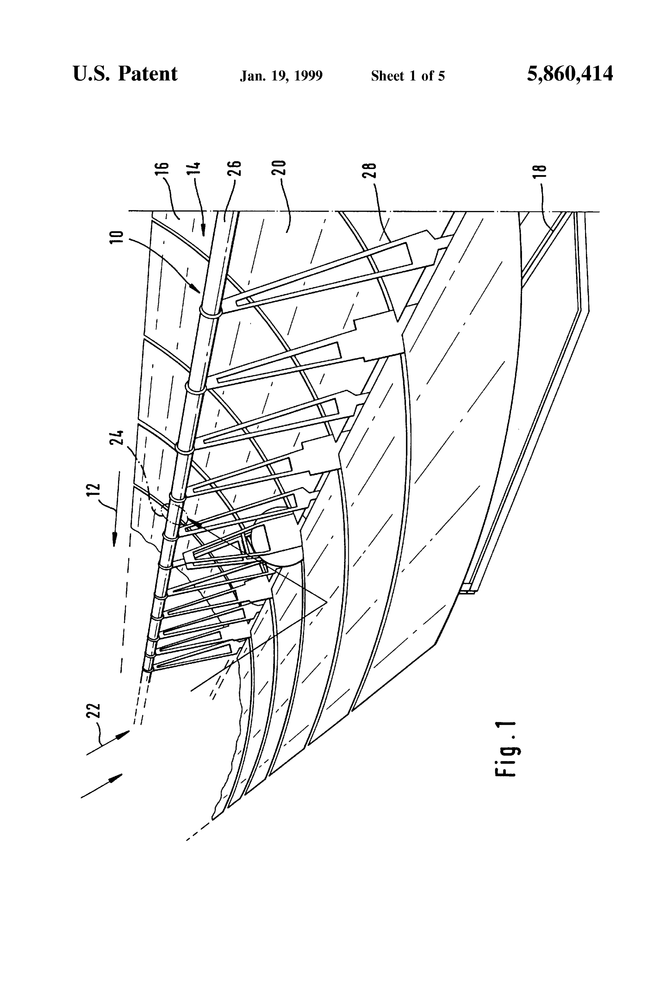
BRIEF DESCRIPTION OF THE DRAWINGS Due to the helical arrangement of the elevations 50, the
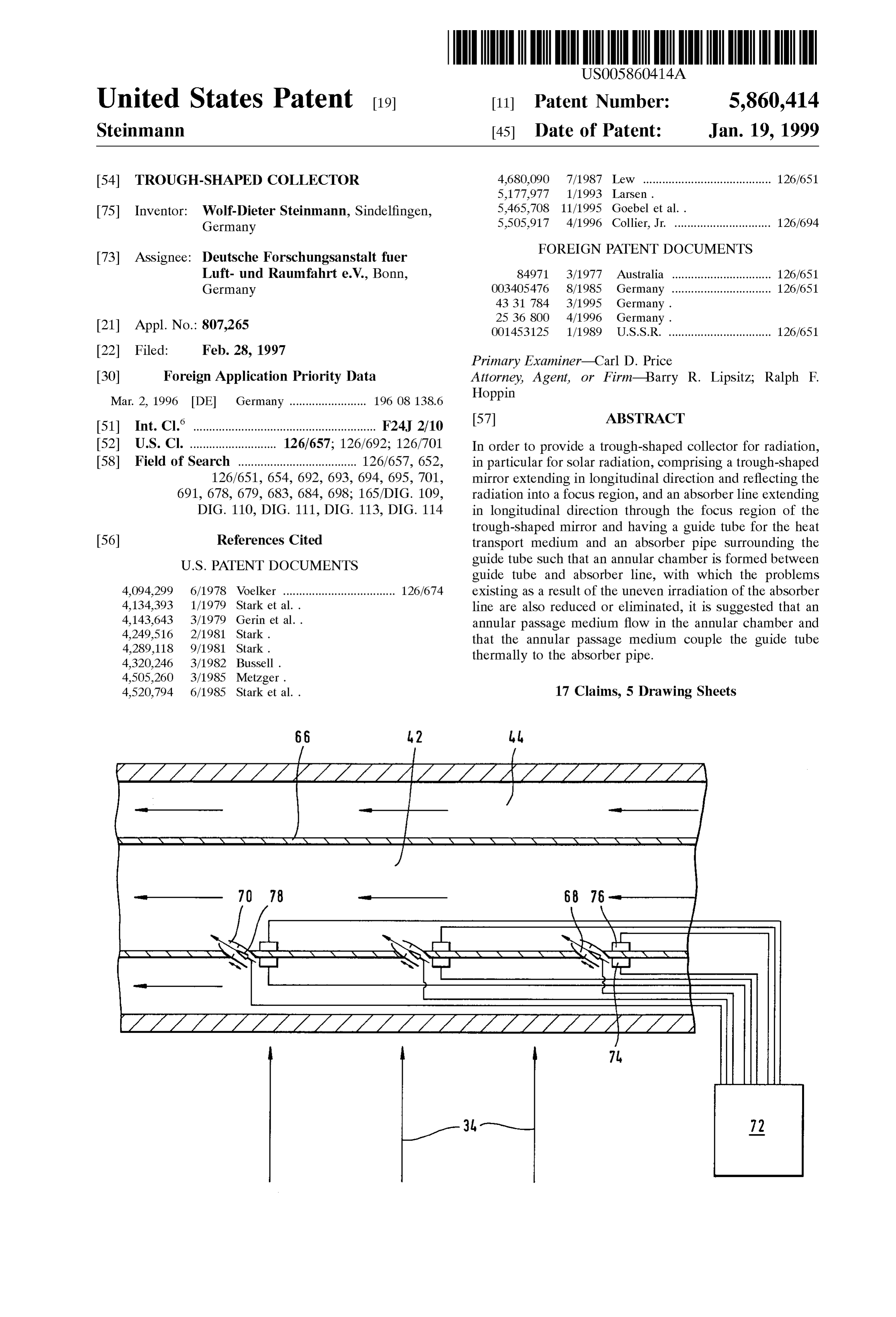
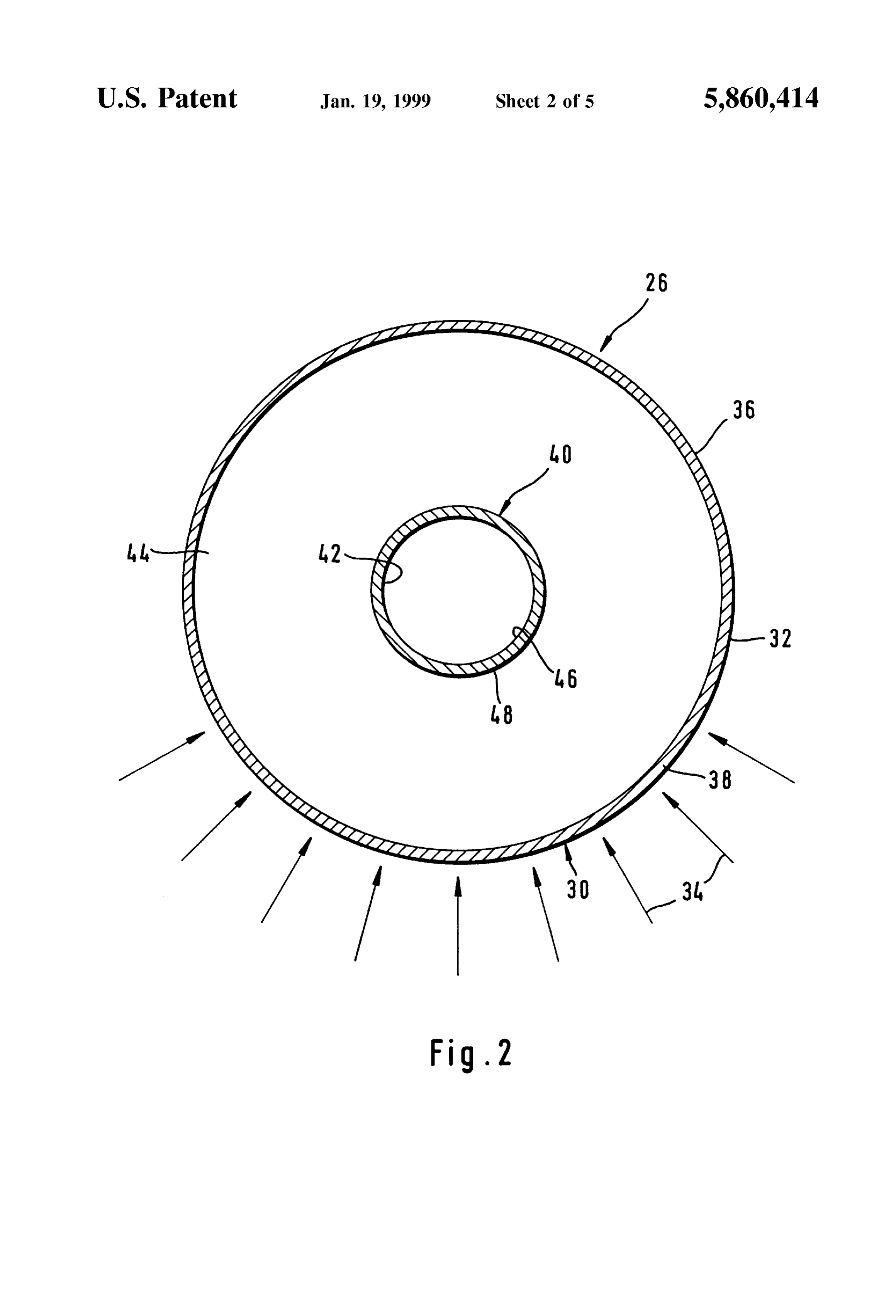
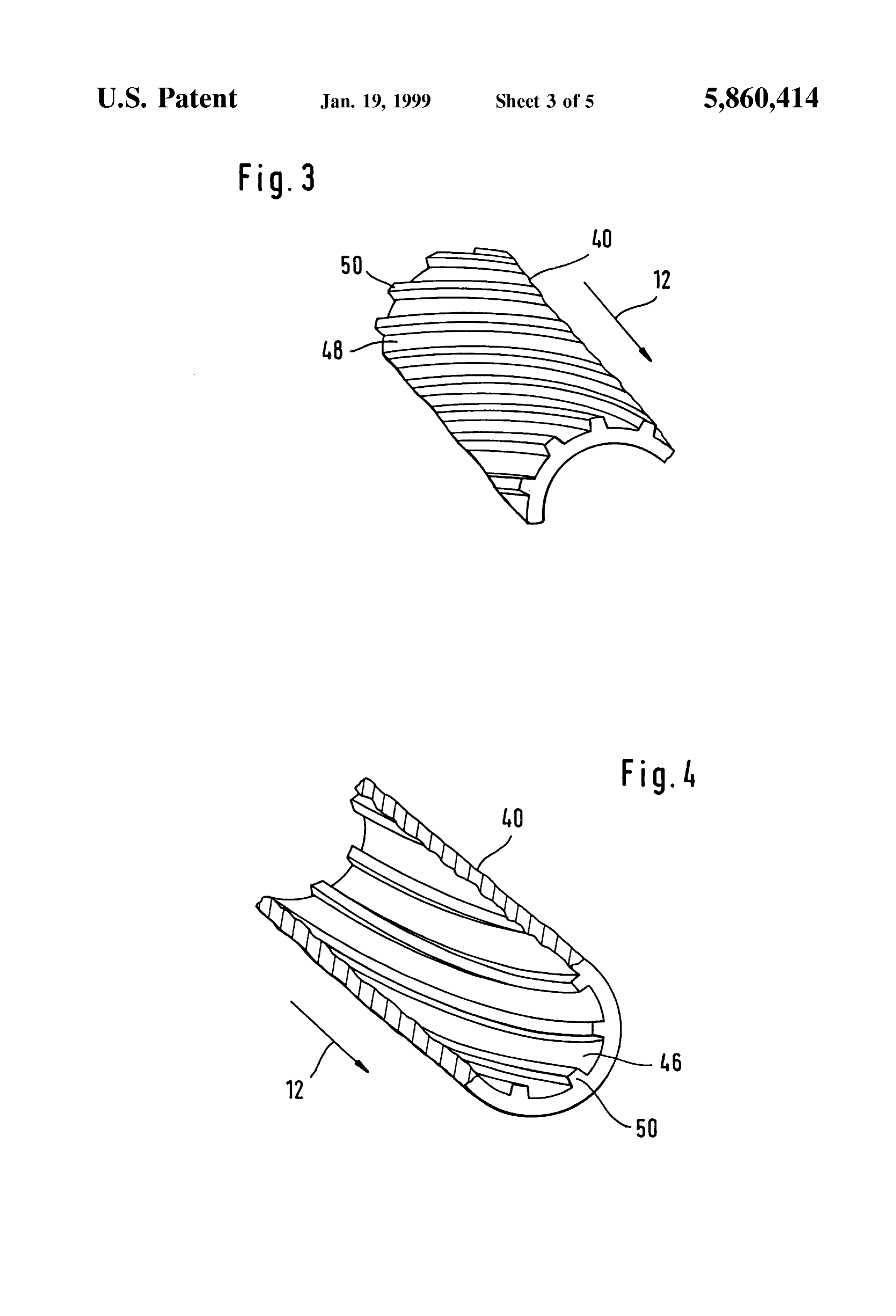
FIG. 1 shows a Schematic, perspective illustration of an annular passage medium flowing in the annular passage 44 inventive trough-shaped collector; is given an angular momentum which promotes the inter FIG. 2 shows a croSS Section through an inventive mixing of the annular passage medium and thus leads to a absorber line; more uniform heating of the annular passage medium over the entire cross section (FIG. 2) of the annular chamber 44.
FIG. 3 shows a cross section through an inventive varia 40 Again tion of a guide tube, showing the inner Side of the guide tube; evenly asin circumferential a result of this, the guide tube 40 is heated more direction over its outer cylindrical
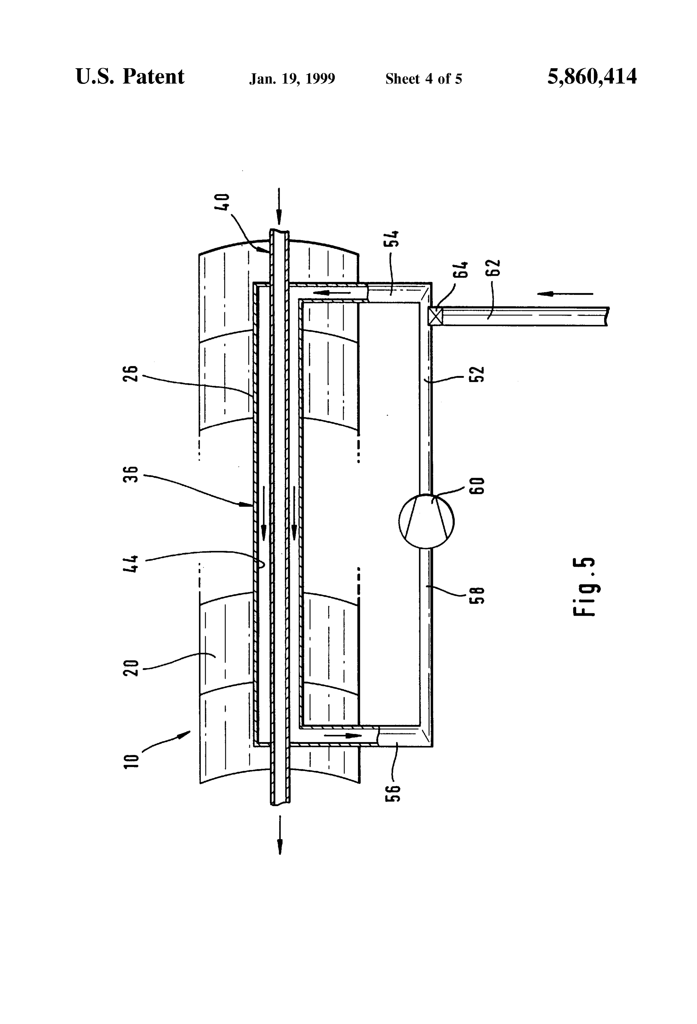
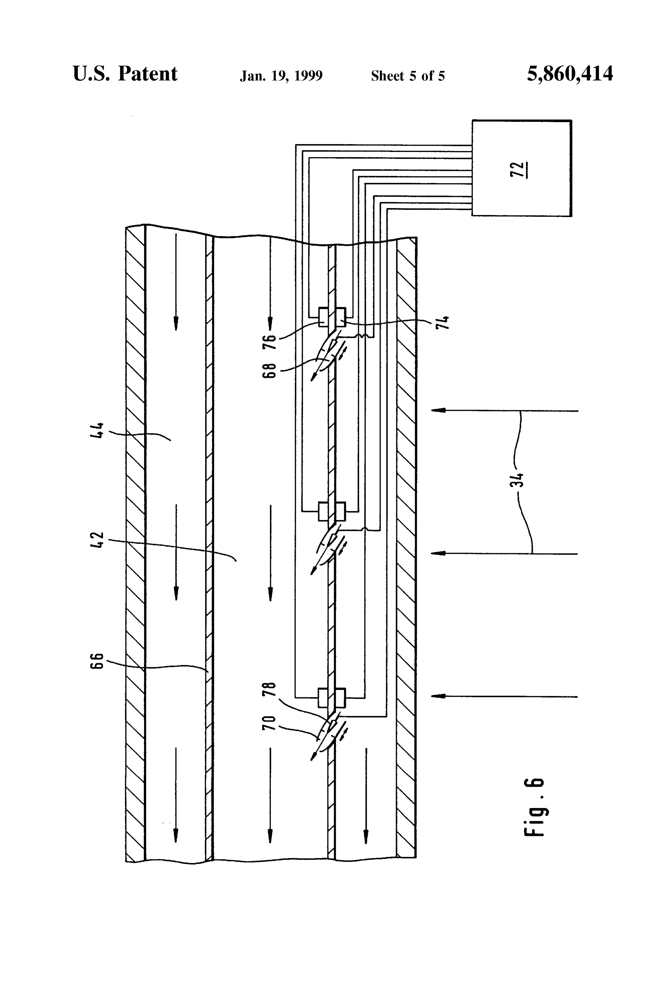
FIG. 4 similar to FIG. 3 but now showing the outer side Surface 48 by the annular passage medium. of the guide tube, In a further variation (FIG. 4), the inner cylindrical FIG. 5 shows a schematic illustration of a closed circuit 45 surface 46 of the guide tube 40 likewise has a structure. This for annular passage medium and comprises elevations 50 which protrude from the inner FIG. 6 shows a longitudinal section of the absorber line. cylindrical surface 46 in the direction of the interior of the
DETAILED DESCRIPTION OF THE
tube and extend helically at an angle to the longitudinal
INVENTION direction 12 and at a distance parallel to one another. This 50 Structure Sees to it that the heat transport medium flowing in
One embodiment of an inventive trough-Shaped collector the interior of the guide tube 40 is given an angular momen is illustrated in FIG. 1, the trough-shaped collector desig tum and thereby intermixed better. The heat transport nated as a whole as 10 extending in a longitudinal direction medium can thus absorb the heat transferred from the 12 and having a trough-shaped mirror 12 which has indi annular passage medium flowing in the annular chamber 44 vidual mirror elements 16 which preferably have a parabolic 55 to the guide tube 40 in an efficient manner. shape and are mounted on a mirror frame 18. The mirror The annular passage medium is conveyed in a closed Surfaces 20 reflect the incoming radiation 22 towards a focal circuit 52 (FIG. 5). The circuit comprises the annular cham line 24, the absorber line 26 being mounted in the region of ber 44 extending inside the trough-shaped collector 10; a the focal line 24 and being held by Support struts 28 at a line 54 which opens into the annular chamber 44 in the defined distance in relation to the mirror Surfaces 20. 60 vicinity of the one end of the trough-shaped collector 10 and The absorber line 26 comprises an absorber screen 30, the via which annular passage medium flows into the annular absorber Surfaces 32 of which absorb the radiation 34 chamber 44, heat transport medium and annular passage reflected from the mirror Surface 20. In the variation of an medium having the same direction of flow in the interior of embodiment shown in FIG. 2, an absorber pipe 36 forms the the trough-shaped collector 10; a line 56, into which the absorber screen 30. A cylinder element 38 of the absorber 65 annular chamber 44 opens in the vicinity of the other end of screen 30 facing the mirror is irradiated as a result of the the trough-shaped collector 10 and through which annular reflected radiation 34. passage medium flows out of the annular chamber 44; a line
Page 9
S 6 58 which connects the lines 54 and 56 with one another and particular, the risk is imminent of the fluid annular passage thus completes the circuit 52. medium vaporizing, the control unit 72 provides for annular The circuit 52 has a pump 60 which generates the nec passage medium to be sprayed into the interior of the guide essary flow Velocity of the annular passage medium in the tube 40 from the annular chamber 44 via the nozzle elements circuit 52. Since the annular passage medium flowing in the 70.
circuit 52 serves to transfer heat, it is advantageous when the The corresponding amount of annular passage medium mass flow rate, generated by the pump 60, of annular which has been sprayed into the guide tube 40 via the nozzle passage medium through the annular chamber 44 in the elements 70 is again fed into the circuit 52 via the valve 64. trough-shaped collector 10 is greater than the mass flow rate This means that a cooling of the annular passage medium in of heat transport medium flowing in the guide tube 40 the circuit 52 occurs. The flow capacity through the nozzle through the trough-shaped collector 10. For example, the elements 70 is thereby controlled such that the optimum mass flow rate in the annular chamber 44 could be greater operating temperature is reached in the annular passage approximately by a factor of ten than the mass flow rate in medium.
the guide tube 40. In order to control the flow capacity through the nozzle The lines 54, 56 and 58 and the pump 60 are preferably 15 elements, these have a valve drive 78. The valve drive 78 is arranged Such that they do not mask the radiation 34 advantageously an electric motor which is remote-controlled reflected from the mirror surface 20 on its path to the by the control unit 72.
absorber Screen 30. Additional control possibilities also result. If, for The annular passage medium in the circuit 52 is Subject to example, the Supply of the heat transport medium into the a pressure which, when water is used as annular passage trough-shaped collector 10 is interrupted, the case may then medium, can be, for example, in the range of approximately occur that the absorber line 26 is no longer adequately 100 to 200 bars and so the water used in this case as annular cooled and thus damage is impending. When the tempera passage medium is present in the fluid State at the maximum ture sensors 76 register temperatures in the interior 42 of the temperatures which can be attained in the trough-shaped guide tube 40 which are too high, the control unit 72 collector 10. It is advantageous when losses of annular 25 provides for annular passage medium to be increasingly passage medium and thus losses of pressure in the circuit 52 sprayed into the guide tube 40 from the circuit 52 via the can be compensated. The circuit 52 therefore has an addi nozzle elements 70 so that an adequate amount of fluid is tional Supply line 62, through which annular passage located in the interior 42 of the guide tube 40 and an medium which is preferably preheated can be fed into the adequate cooling of the absorber line 26 is ensured. The amount of fluid sprayed into the guide tube 40 and thus circuit 52 via a valve 64.
In a variation of an inventive embodiment, the same missing in the circuit 52 is fed into the circuit 52 again via the valve 64 and the supply line 62.
medium, preferably water, is used as heat transport medium What is claimed is:
and as annular passage medium. 1. A trough-Shaped collector for radiation, comprising: This results in the possibility of undertaking a temperature a trough-shaped mirror extending in a longitudinal direc regulation by way of Spraying annular passage medium from 35 tion and reflecting the radiation into a focus region; and the annular chamber 44 into the interior 42 of the guide tube an absorber line extending in Said longitudinal direction 40. through the focus region of the trough-Shaped mirror; As shown in FIG. 6, the walls 66 of the guide tube 40 have Said absorber line comprising:
for this purpose openings 68, in which nozzle elements 70 an absorber pipe having an absorber Screen which are Seated. The openingS 68 are thereby arranged in Spaced 40 absorbs the radiation reflected from said mirror; relationship in longitudinal direction 12. The distance a guide tube adapted to carry a heat transport medium between them need not necessarily be constant. For for transporting heat resulting from radiation example, it could be advantageous when the distance is absorbed by said absorber screen; Shorter in the vicinity of the one end of the trough-shaped Said absorber pipe Surrounding the guide tube Such that collector 10, at which the heat transport medium flows into 45 an annular chamber is formed between Said guide the trough-shaped collector 10, and the distance is greater in tube and Said absorber pipe, the vicinity of the other end, at which the heat transport Said annular chamber being adapted to carry an annular medium flows out of the trough-shaped collector 10. One or passage medium in Said longitudinal direction via a Several nozzle elements 70 can be arranged in circumferen closed circuit to efficiently transfer the heat resulting tial direction. 50 due to Said absorption from Said absorber pipe to Said The nozzle elements 70 can be controlled with respect to guide tube and heat Said guide tube essentially over their rate of flow, each nozzle element preferably being its entire circumference. actuatable individually. This control takes place via a control 2. A trough-shaped collector as defined in claim 1, unit 72. wherein:
A temperature Sensor 74 is preferably associated with 55 Said has a Substantially circular croSS-Section, and Said each nozzle element 70 and this is favorably seated on the absorber Screen is disposed at an outer circumference outer cylindrical surface 48 of the guide tube 40 in front of of Said absorber pipe for absorbing the radiation a nozzle element 70-in relation to the direction of flow. The reflected from Said trough-shaped mirror. temperature Sensors 74 measure the temperature in the 3. A trough-shaped collector as defined in claim 1, annular passage medium and pass these temperature values 60 wherein:
to the control unit 72. the annular passage medium comprises the same Sub Temperature Sensors 76 are likewise Seated on the inner stance as the heat transport medium. cylindrical Surface 46 of the guide tube 40. They measure the 4. A trough-shaped collector as defined in claim 1, further temperature in the heat transport medium and likewise pass comprising:
these values to the control unit 72. 65 nozzle elements arranged in the guide tube for introducing If the temperature in the annular passage medium mea Said annular passage medium from Said annular cham Sured by the temperature Sensors 74 is too high So that, in ber into Said guide tube.
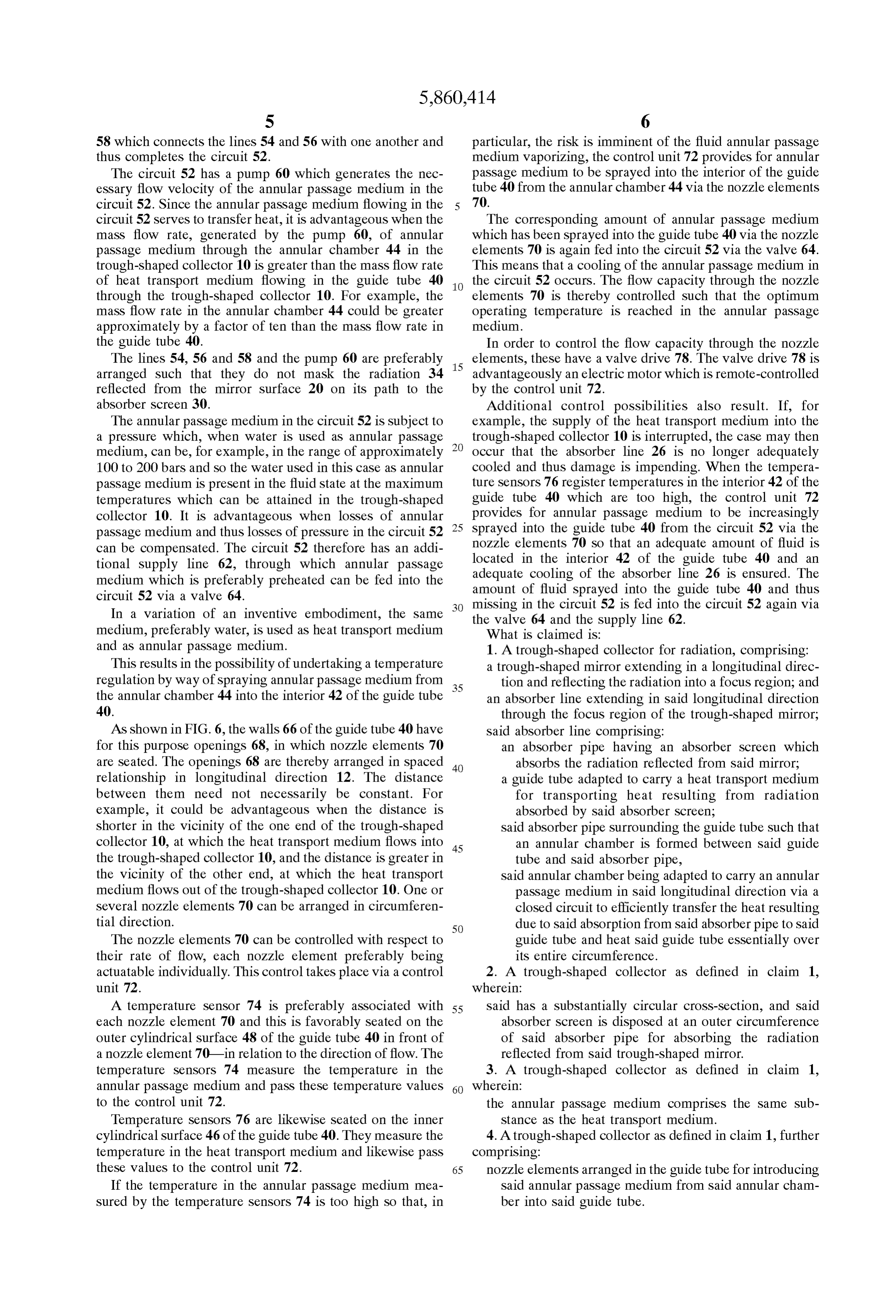
Page 10
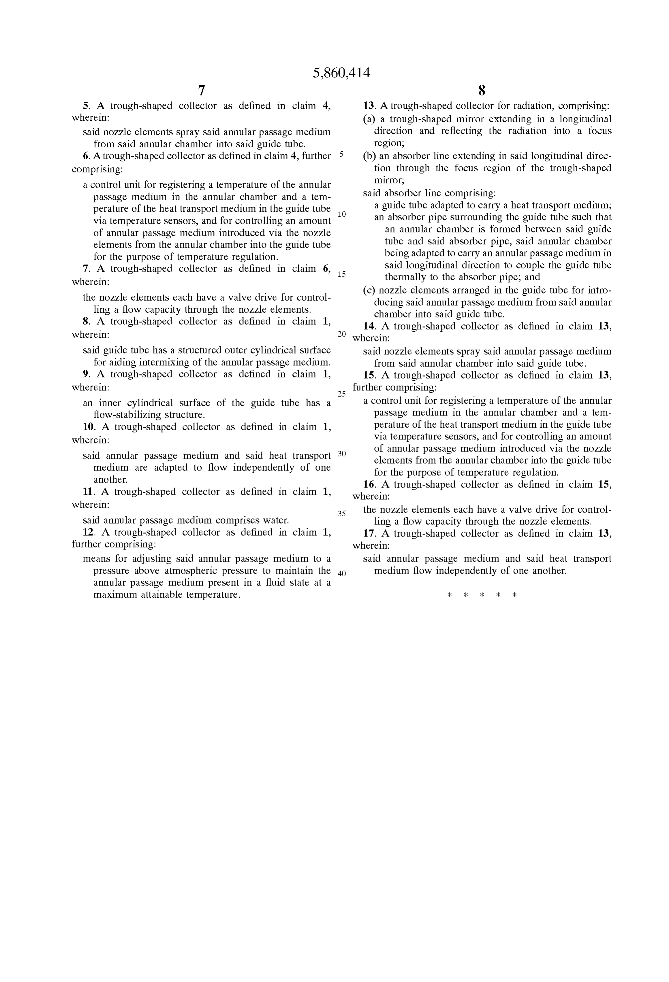
5. A trough-shaped collector as defined in claim 4, 13. A trough-shaped collector for radiation, comprising: wherein: (a) a trough-shaped mirror extending in a longitudinal Said nozzle elements spray Said annular passage medium direction and reflecting the radiation into a focus from Said annular chamber into Said guide tube. region;
6. A trough-shaped collector as defined in claim 4, further (b) an absorber line extending in Said longitudinal direc comprising: tion through the focus region of the trough-shaped a control unit for registering a temperature of the annular mirror;
passage medium in the annular chamber and a tem Said absorber line comprising:
perature of the heat transport medium in the guide tube a guide tube adapted to carry a heat transport medium; via temperature Sensors, and for controlling an amount an absorber pipe Surrounding the guide tube Such that of annular passage medium introduced via the nozzle an annular chamber is formed between Said guide elements from the annular chamber into the guide tube tube and Said absorber pipe, Said annular chamber for the purpose of temperature regulation. being adapted to carry an annular passage medium in 7. A trough-shaped collector as defined in claim 6, 15 Said longitudinal direction to couple the guide tube wherein: thermally to the absorber pipe, and the nozzle elements each have a valve drive for control (c) nozzle elements arranged in the guide tube for intro ling a flow capacity through the nozzle elements. ducing Said annular passage medium from Said annular 8. A trough-shaped collector as defined in claim 1, chamber into Said guide tube. wherein:
14. A trough-shaped collector as defined in claim 13, wherein:
Said guide tube has a Structured outer cylindrical Surface Said nozzle elements spray Said annular passage medium for aiding intermixing of the annular passage medium. from Said annular chamber into Said guide tube. 9. A trough-shaped collector as defined in claim 1, 15. A trough-shaped collector as defined in claim 13, wherein:
further comprising:
an inner cylindrical Surface of the guide tube has a a control unit for registering a temperature of the annular flow-stabilizing Structure. passage medium in the annular chamber and a tem 10. A trough-shaped collector as defined in claim 1, perature of the heat transport medium in the guide tube wherein: via temperature Sensors, and for controlling an amount Said annular passage medium and Said heat transport of annular passage medium introduced via the nozzle medium are adapted to flow independently of one elements from the annular chamber into the guide tube another.
for the purpose of temperature regulation.
16. A trough-shaped collector as defined in claim 15, 11. A trough-shaped collector as defined in claim 1, wherein:
wherein: the nozzle elements each have a valve drive for control
Said annular passage medium comprises water. ling a flow capacity through the nozzle elements. 12. A trough-shaped collector as defined in claim 1, 17. A trough-shaped collector as defined in claim 13, further comprising: wherein:
means for adjusting Said annular passage medium to a Said annular passage medium and Said heat transport preSSure above atmospheric pressure to maintain the 40 medium flow independently of one another. annular passage medium present in a fluid State at a maximum attainable temperature. k k k k k
Page 11
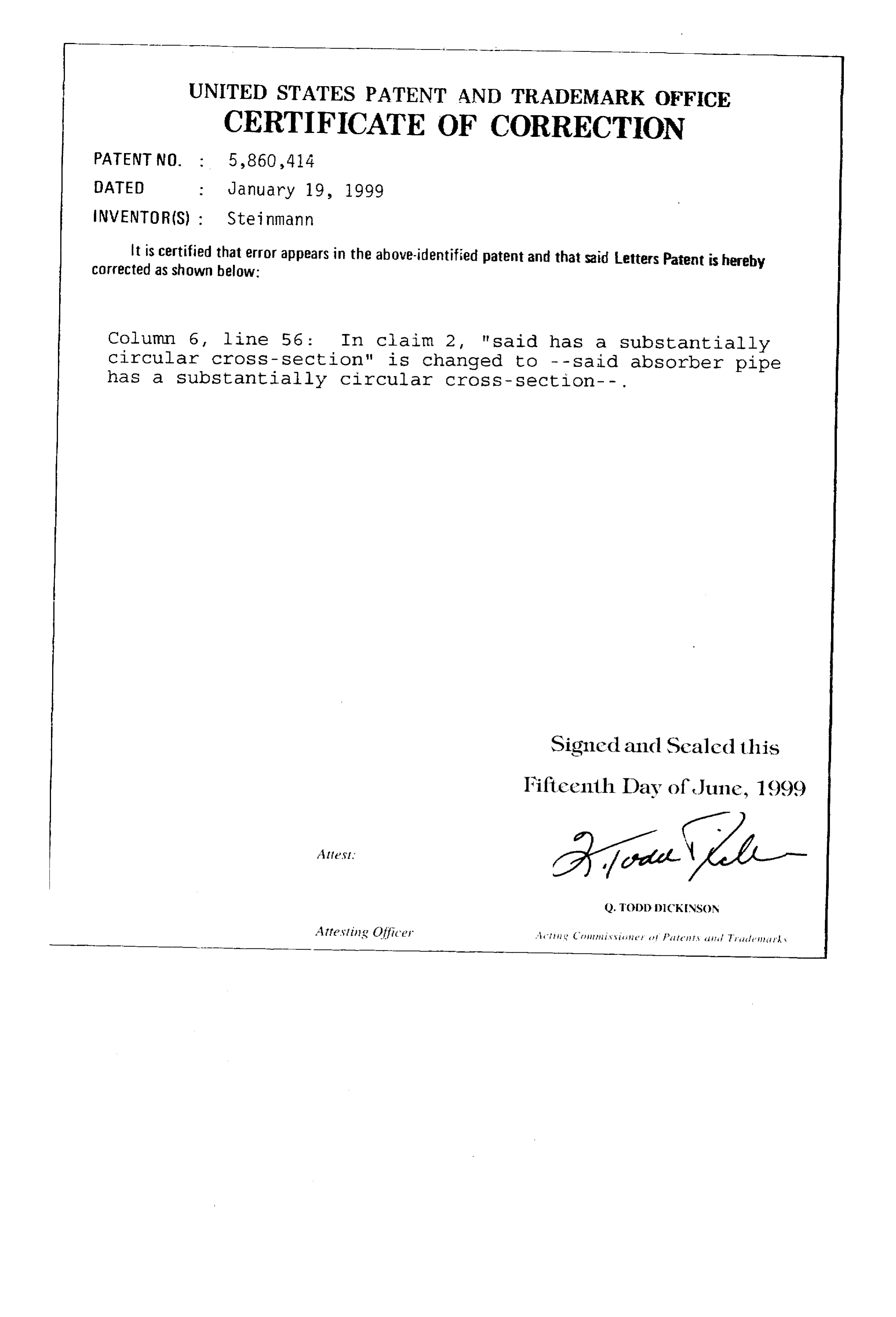
UNITED STATES PATENT AND THADEMARK OFFICE
CERTIFICATE OF CORRECTION
INVENTOR(S) : Steinmann
It is certified that error appears in the above-identified patent and that said Letters Patent is hereby corrected as shown below:
Column 6, line 56: In claim 2, "Said has a substantially circular cross-section" is changed to -- said absorber pipe has a substantially Circular CrOSS - Section - . Signed and Sealed this
IFifteenth Day of June, 1999
Q. TODD DICKINSON
Attesting Officer Ali Crinii is site it fit its edit Tule in k \
Provenance
- Collection
- Cited prior art
- Original PDF
- patentimages.storage.googleapis.com →
- Filed
- 1997-02-28
- Pages
- 11
- Method
- pdftotext (the PDF's own text layer) + pdftoppm 300dpi page scans
- Source
- Google Patents bibliographic record
- Granted
- 1999-01-19
- Inventors
- Wolf-Dieter Steinmann; Deutsches Zentrum fuer Luft und Raumfahrt eV
- Transcribed from
- patentimages.storage.googleapis.com →