patent · US5465708
Trough-shaped collector
14 November 1995
Page 1 — bibliographic record
United States Patent (19) 11 Patent Number: 5,465,708 Goebel et al. 45) Date of Patent: Nov. 14, 1995 54 TROUGH-SHAPED COLLECTOR 3,923,038 12/1975 Cutchaw ................................. 126/635
75) Inventors: Olaf Goebel, Stuttgart; Klaus 4,214,572 7/1980 Gonder. Hennecke, Lohmar, both of Germany 4,217,882 8/1980 Feldman, Jr. ...................... 165/10426 4,296,735 10/1981 Liorach ................................... 126/692 73) Assignee: Deutsche Forschungsanstalt fuer 4,320,246 3/1982 Russell ..................... ... 126/636 Luft- und Raumfahrt e.V., Bonn, 4,505,260 3/1985 Metzger ................... ... 126/683 Germany 4909,316 3/1990 Kamel et al. ... 165,104.26 4,911,144 3/1990 Godett et al. ........................... 126/636 (21) Appl. No.: 307,904 FOREIGN PATENT DOCUMENTS 22 Filed: Sep. 16, 1994. 3025826 1/1981 Germany. (30) Foreign Application Priority Data Primary Examiner James C. Yeung Sep. 18, 1993 DEI Germany .......................... 43 31 785.5 Attorney, Agent, or Firm-Barry R. Lipsitz (51 Int. CI. .............................. F24J 2/32 (57) ABSTRACT 52 U.S. Cl. .......................... 126/635; 126/694; 126/652;
65/104.26 A trough-shaped collector for solar radiation for steam 58) Field of Search ..................................... 126/635, 692, generation. A trough-shaped mirror extending in a longitu 126/651, 652, 654, 655, 656, 636, 637, dinal direction receives and reflects radiation onto an 684, 693, 638; 165/104.26 absorber line enclosing within its interior a steam generator tube. Heat is transferred transversely from the absorberline (56) References Cited to the steam generator tube by a heat pipe structure.
1,661,473 3/1928 Goddard et al. . 11 Claims, 4 Drawing Sheets
Page 2
Drawing sheet — no readable text.
Page 3
Drawing sheet — no readable text.
Page 4
Drawing sheet — no readable text.
Page 5
Drawing sheet — no readable text.
Page 6
TROUGH-SHAPED COLLECTOR With respect to the design of the vaporizer tubes, no details have so far been given. In a particularly advantageous
BACKGROUND OF THE INVENTION
embodiment, for example, the vaporizer tubes are designed for pressure of more than 25 bar, preferably to vaporize
The invention relates to a trough-shaped collector for water directly and use the steam for driving steam turbines. radiation, in particular for solar radiation, comprising a With respect to the design of the absorber surface, no trough-shaped mirror extending in a longitudinal direction details have so far been given. In the simplest case, the and reflecting the radiation into a focus region, and an recess could have an approximately rectangular or trapezoi dal cross section. It is, however, particularly advantageous absorber pipe member extending in the longitudinal direc tion in the focus region of the trough-shaped mirror, a heat 10 for the recess to have a channel with a curved cross section. In this case, the absorber surface is preferably a surface transport medium flowing through the pipe member for borne by the channel and therefore a concave surface. taking away the resulting heat and the pipe member having In this respect, it is particularly expedient for the absorber a recess extending in its longitudinal direction and being located between two side edges, this recess facing the 15 other side extend surface to edge.
from one side edge of the channel to the trough-shaped mirror with an opening formed by the side edges and being limited by an absorber screen bearing an With respect to the arrangement of the channel, no addi absorber surface. tional details have been given in conjunction with the Trough-shaped collectors of this type are known from preceding explanations of the individual embodiments. In an advantageous embodiment, for example, the channel is
U.S. Pat. No. 1,661473. 20 seated at its rim on a support of the absorber line. In these trough-shaped collectors, the absorber line is The Support could be any type of supporting construction. preferably formed by a C-shaped absorber pipe member It is, however, particularly expedient for the support to be a which, for its part, bears the absorber surface. The problem cylinder with such absorber pipe members is that the C-shaped space tion sincecasing segment extending in the longitudinal direc for the heat transport medium does not allow any efficient 25 particularly this is, from a constructional point of view, simple to produce and connect with the channel.
operation thereof.
The object underlying the invention is therefore to In a particularly advantageous embodiment, the support improve a trough-shaped collector of the generic type such and the channel togetherform the absorber pipe member and that this can be operated as efficiently as possible. enclose between them an interior of the absorber pipe member.
SUMMARY OF THE INVENTION
The inventive solution allows, in particular, the absorber surface to be adapted to an extension of the focus region
This object is accomplished in accordance with the inven transversely to the longitudinal axis, preferably to dimension tion, in a trough-shaped collector of the type described at the this essentially equal to the extension of the focus region outset, in that the absorber pipe member has an interior, that 35 transversely to the longitudinal direction. a vaporizer tube having an essentially round cross section In order to ensure, in this case, an efficient heat transport extends in the interior of the absorber pipe member for between the channel bearing the absorber surface and the transporting heat in the longitudinal direction and that the vaporizer tube, it is preferable for a heat pipe thermally vaporizer tube is thermally coupled to the absorber pipe coupling the channel and the vaporizer tube essentially in a member via a heat transport medium present between the 40 direction transversely to the longitudinal direction to be vaporizer tube and the absorber screen for transporting heat arranged between the channel and the vaporizer tube. transversely to the longitudinal direction. The heat pipe could be a constructional element which is Such provision of a separate vaporizer tube allows the independent of the channel and the vaporizer tube and is in dimensions of this vaporizer tube to be adapted to the given thermal contact therewith. It is, however, particularly advan circumstances for transporting heat away as effectively as 45 tageous for the interior of the absorber pipe member which possible by means of the heat transport medium and, thus, surrounds the vaporizer tube to form a vapor chamber of the this vaporizer tube may be designed independently of the heat pipe.
cross section of the focus region so that the absorber surface In addition, the heat pipe is, in the simplest case, con can be dimensioned independently of the cross section of the structed such that the vaporizer tube and the absorber pipe vaporizer tube. 50 member represent housing elements thereof. The advantage of the inventive solution is therefore to be An effective action of the heat pipe can be attained when seen in the fact that due to the arrangement of the vaporizer the channel bears a capillary structure of the heat pipe, tube separate from the absorber pipe member the vaporizer which keeps a heat transfer medium of the heat pipe tube can, on the one hand, be dimensioned with respect to its 55 absorbed, on a side facing away from the absorber surface. stability for high steam pressures without needing to take the In this example, the vaporizer tube forms, in particular, in shape of the absorber surface into consideration. the preferred case a condensation surface for the heat In addition, the coupling between absorber surface and transfer medium with an outer side so that the heat pipe, in vaporizer tube by means of the heat transport medium can this case, heats the vaporizer tube uniformly in circumfer expediently accomodate to an acceptable deformation of the 60 ential direction.
vaporizer tube due to uneven heating. Moreover, in an additional, advantageous embodiment the In this respect, it is particularly advantageous for the heat support is likewise coupled to the channel by the heat pipe transport medium to heat the vaporizer tube uniformly in so that the temperature of the support walls corresponds circumferential direction. essentially to that of the channel bearing the absorber This means that the problems which result from uneven 65 surface.
deformation of the vaporizer tube due to uneven heating In order to avoid any removal of heat from the support, it thereof are solved. is preferable for the support to be covered with an insulation
Page 7
layer so that heat will not be discharged to the surroundings impinged by solar radiation 34 reflected from the mirror from this. surface 20.
Furthermore, any discharge of heat to the surroundings by One embodiment of the inventive absorber screen 30 convection can be reduced by having a cover which is having an absorber surface 32 which absorbs the solar permeable to radiation engaging over the absorber surface. radiation 34 reflected by the mirror surface 20 is preferably This cover is arranged, in the simplest case, such that it part of an absorber pipe member designated as a whole as preferably extends arcuately over the absorber surface. 36, which comprises a channel 38 and a support 40 for the channel 38.
In another, advantageous possibility, the absorber pipe member is arranged as a whole in a protective casing which O 44,The channel 38 extends between two side edges 42 and which extend parallel to the longitudinal direction 12, represents a cover for the absorber surface with a partial with a concave cross section which extends transversely to section which is permeable to radiation. the longitudinal direction 12 and lies symmetrically between An insulating gas at low pressure or under vacuum is the side edges 42 and 44. A concave surface of the channel preferably provided between the cover and the absorber 38 thereby represents the absorber surface 32 so that the surface. 15 channel 38 forms the absorber screen 30. An inventive absorber surface can, in principle, be The support 40 is, for its part, designed as a cylinder arranged independently of any tracking movement of the casing segment which likewise extends between the side trough-shaped mirror. It is, however, particularly advanta edges 42 and 44, namely with such a radius that an interior geous for the absorber surface to be coupled to a tracking 52, which is crescent-shaped in cross section transversely to movement of the trough-shaped mirror. 20 the longitudinal direction 12, remains between an inner wall This may be realized, in the simplest case, by the absorber 48 of the channel 38 and an inner wall 50 of the support 40. surface being rigidly coupled to a frame of the trough This interior represents the interior of the absorber pipe shaped mirror which is movable in order to carry out the member 36. The support 40 and the channel 38 are prefer tracking movement. ably parts which are connected, preferably welded, to one 25 another in the region of the side edges 42 and 44 and
The heat transport medium is preferably supplied to together form the channel 38.
and/or removed from the absorberline which is movable for tracking via a rotary supply line, even better via a torsion In order to thermally insulate the absorber surface 32 in pipe to avoid rotary seals. relation to the surroundings, a glass cover 54 made of glass which is transparent for the solar radiation 34, preferably
Additional features and advantages of the invention are 30 transparent for visible light and reflecting infrared radiation, the subject matter of the following description as well as the preferably rises above the channel 38, namely between the drawings of several embodiments. side edges 42 and 44. This glass cover is designed to be dome-shaped in cross section transversely to the longitudi
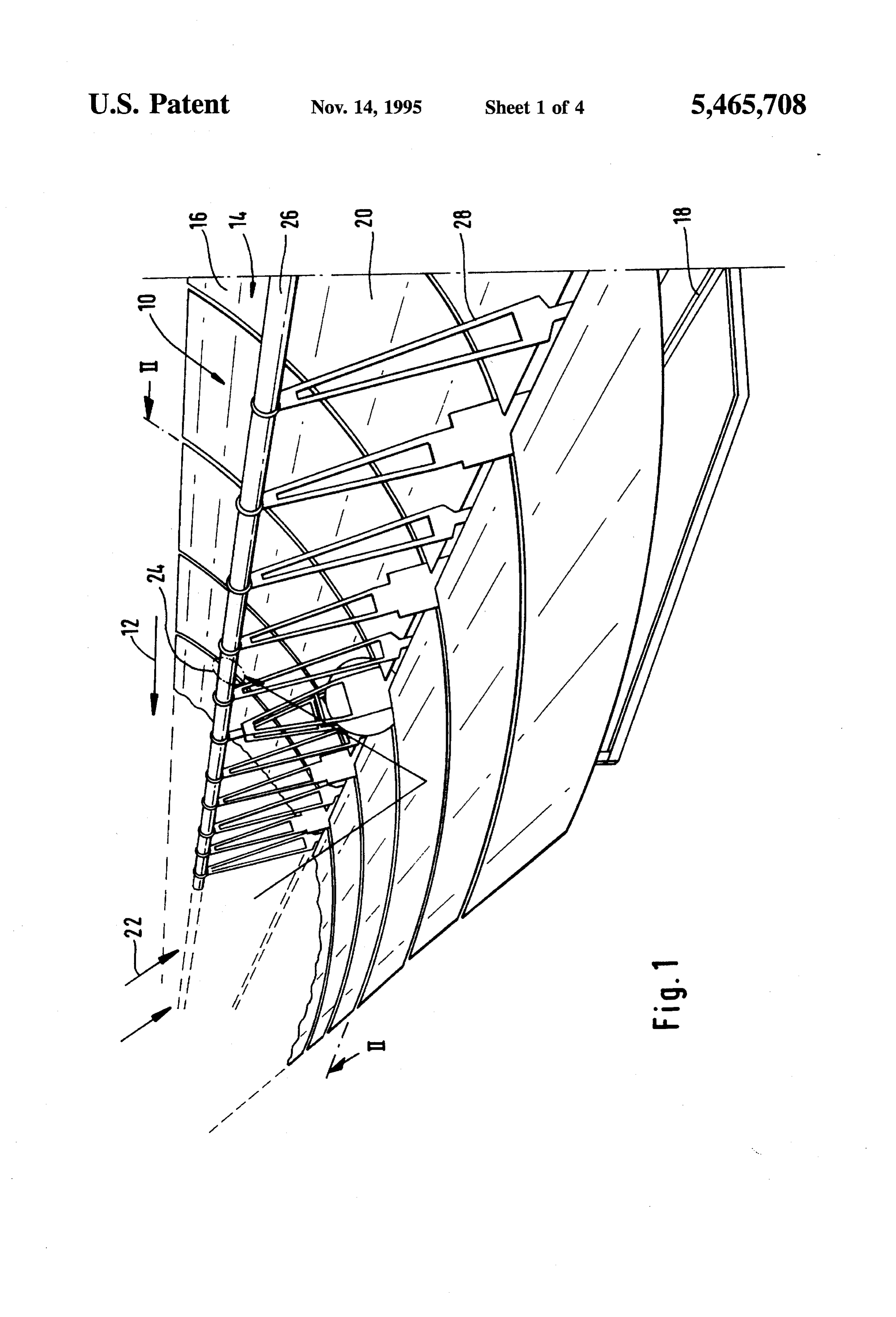
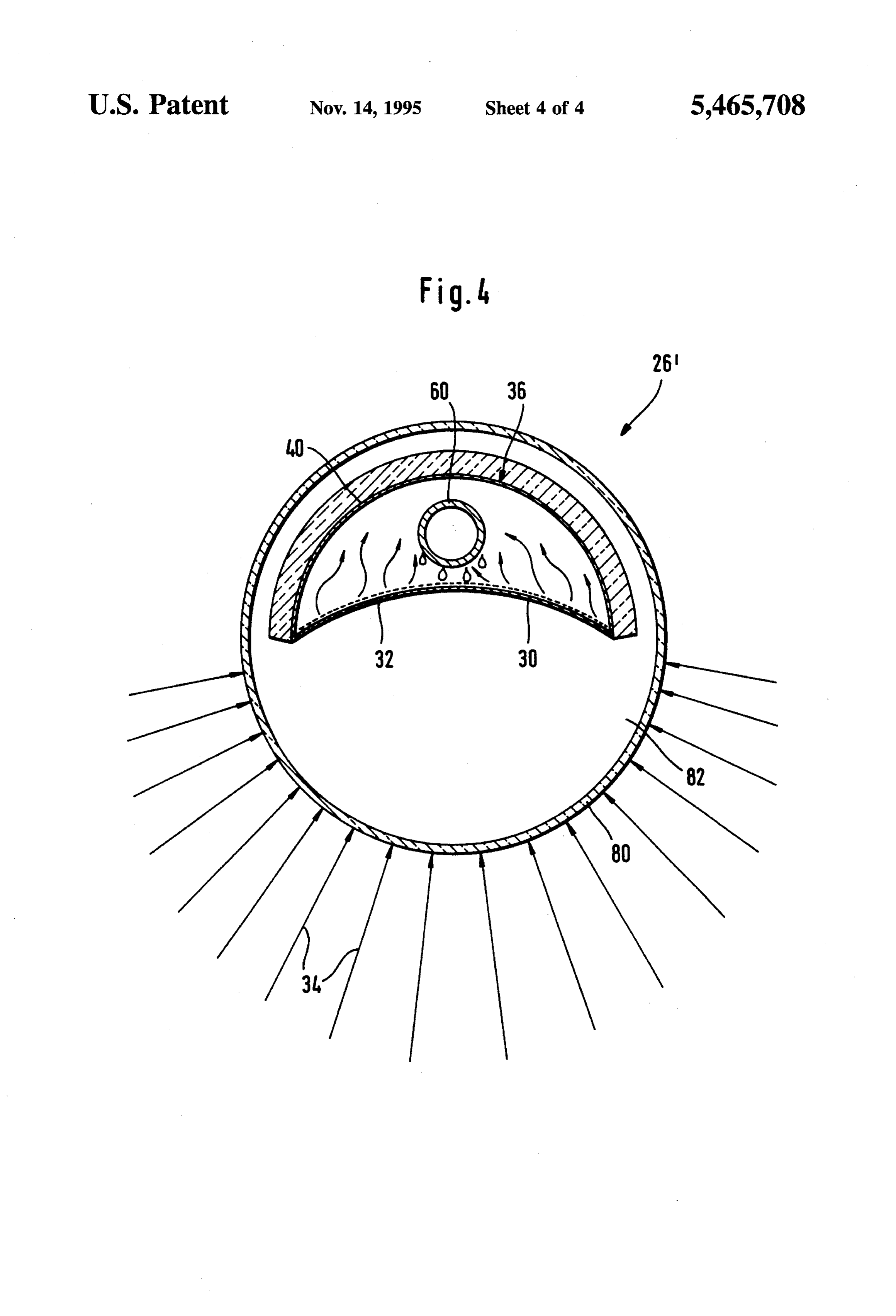
BRIEF DESCRIPTION OF THE DRAWINGS nal direction 12 and insulating gas at a low pressure or under FIG. 1 is a perspective illustration of an inventive trough 35 vacuum is preferably provided between the glass cover 54 and the absorber surface 32.
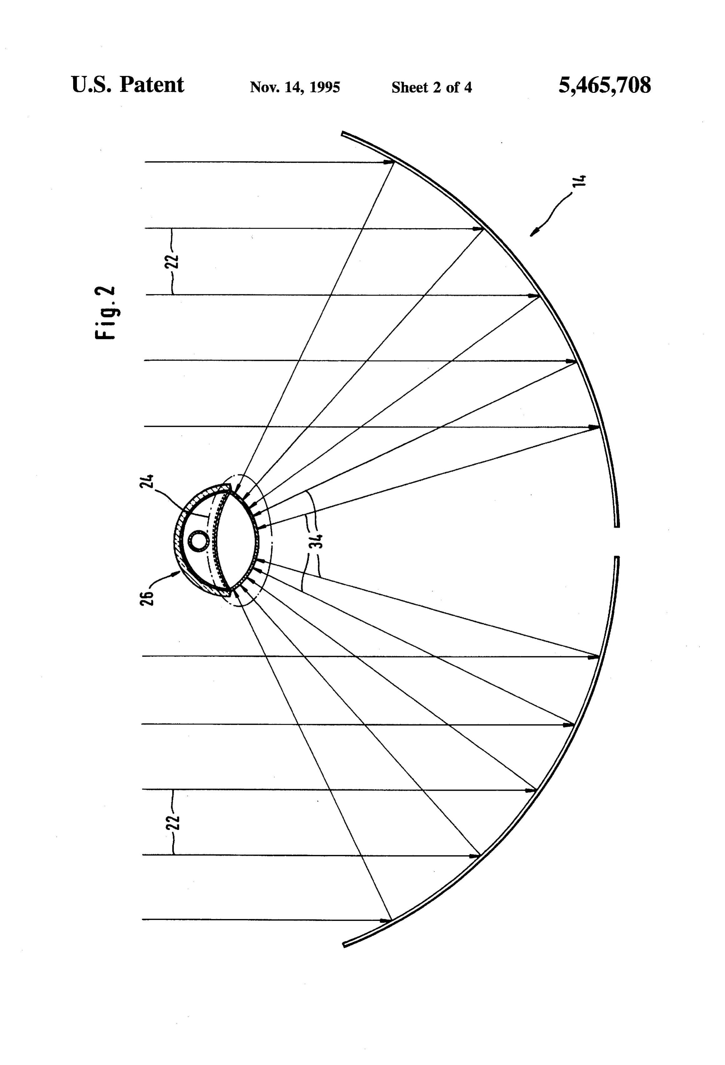
shaped collector,
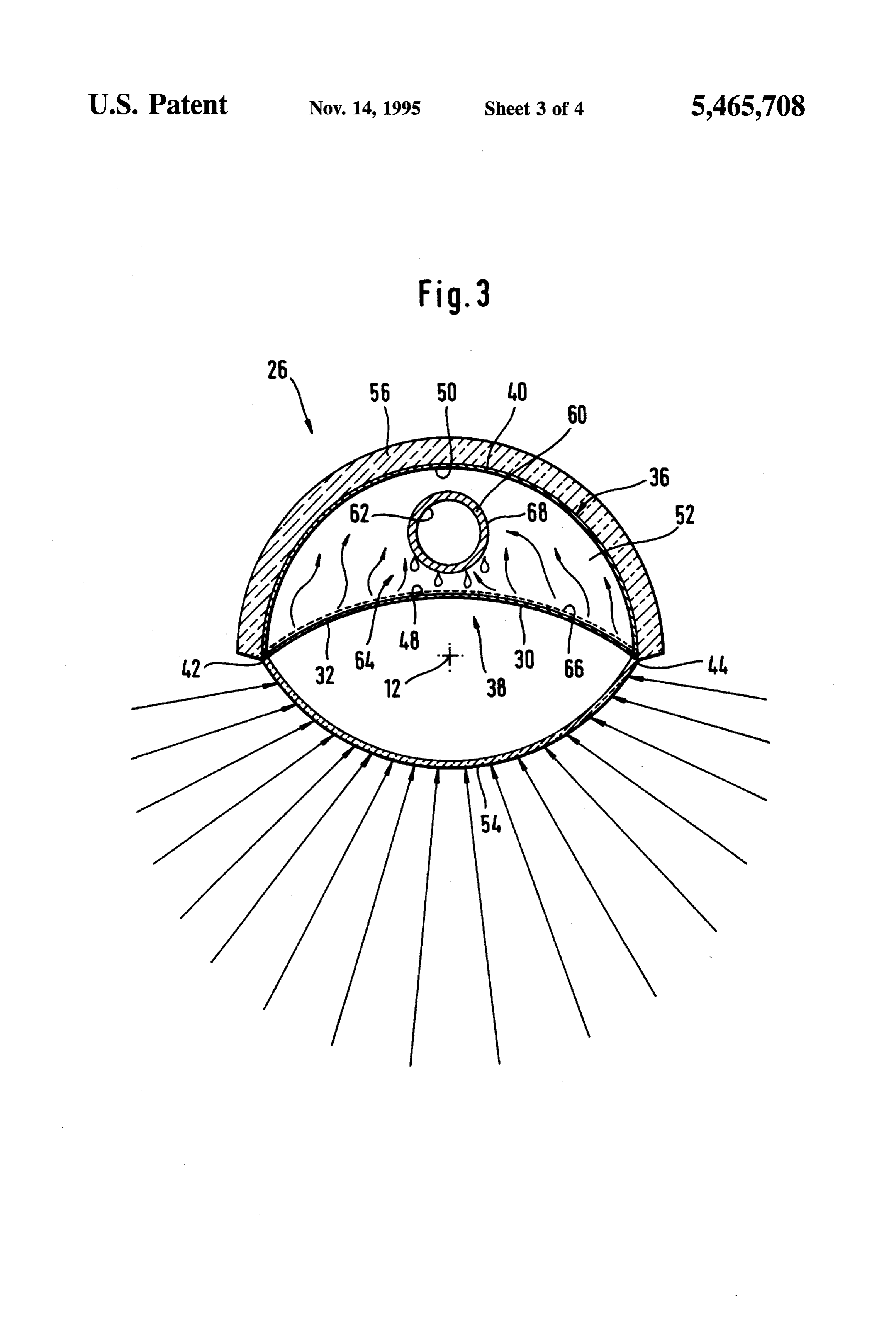
FIG. 2 is a section along line II-II in FIG. 1; Moreover, an insulation layer 56, which covers the sup FIG.3 is an enlarged cross section through a first embodi port 40 from side edge 42 to side edge 44 and reduces any ment of an inventive absorber line and cooling in the region of the support 40, is provided for 40 insulating the support 40 which is arranged on a side of the
FIG. 4 is across section similar to FIG.3 through a second channel 38 facing away from the mirror surface 20. embodiment of an inventive absorber line.
The frame 52 of the inventive absorber pipe member 36
DETAILED DESCRIPTION OF THE
is penetrated by a vaporizer tube 60 which conveys a heat
transport medium in a tube interior 62 for taking away the heat.
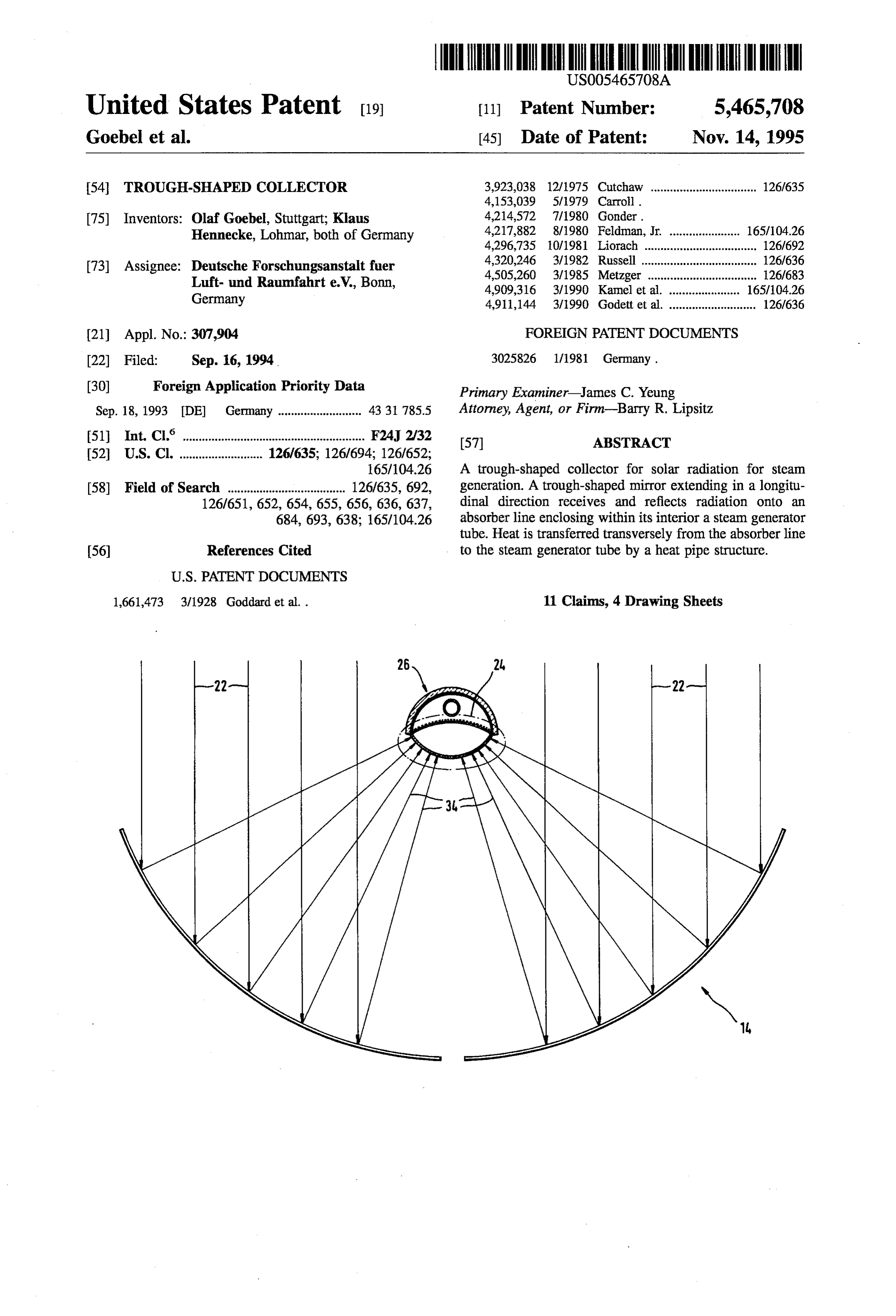
An embodiment of an inventive trough-shaped collector For the thermal coupling between the vaporizer tube 60 illustrated as a whole in FIG. 1 and designated as 10 extends and the absorber screen 30, the interior 52 of the absorber in a longitudinal direction 12, for example over several pipe member 36 which surrounds the vaporizer tube 60 is hundred meters, and comprises a trough-shaped mirror 14 50 designed as a vapor chamber of a heat pipe designated as a which is preferably designed as a parabolic mirror and whole as 64. In the simplest case, from a constructional point constructed of a plurality of mirror elements 16 which are of view, both the support 40 and the vaporizer tube 60 form held on a mirror frame 18 and, together, form a mirror housing elements of a housing of this heat pipe 64. surface 20 which extends in the longitudinal direction 12 The heat pipe 64 comprises, in addition, a capillary and is parabolic transversely to the longitudinal direction 12. 55 structure 66 which is arranged on the inner wall 48 and is The parabolic mirror surface 20 reflects incoming solar saturated by a heat transfer medium, preferably potassium. radiation 22 into a focal line 24 which extends in the The capillary structure 66 holding the heat transfer medium longitudinal direction 12 and in which an absorber line and the absorber screen 30 togetherform a vaporizing region designated as a whole as 26 is located. This absorber line is of the heat pipe 64 while a condensate region is formed by rigidly held via support struts 28 on the mirror frame 18, 60 a circumferential surface of the vaporizer tube 60 which acts which is pivotable to align the mirror surface 20 exactly in as condensation surface 68. The heat transfer medium con relation to the solar radiation 22. The support struts 28 are denses on this condensation surface 68 and drips, in turn, arranged one after the other at regular intervals in the from the condensation surface 68 back to the capillary longitudinal direction in order to hold the absorber line 26 structure 66 which absorbs this and distributes it over its precisely aligned in the focal line 24. 65 entire extension on the inner wall 48 of the absorber screen As illustrated in FIG. 3, the absorberline 26 comprises an 30.
absorber screen 30 which bears an absorber surface 32 Moreover, the inner wall 50 of the support 40 likewise
Page 8
forms a condensation surface to the extent that this does not steam generation, said collector comprising: have the same temperature as the absorber screen 30 and so (a) a trough-shaped mirror extending in a longitudinal the support 40 is also held by the heat pipe 64 at the same direction for reflecting solar radiation into a focus temperature as the absorber screen 30 and, furthermore, region extending in the longitudinal direction; transports the heat efficiently to the vaporizer tube 60 and the heatis passed via this to the heat transport medium conveyed (b) an absorber line comprising: in the tube interior 62. (1) a longitudinally extending support having a recess In a second embodiment of an inventive absorber line, with longitudinally extending edges; and designated as a whole as 26' in FIG. 4, the absorber pipe (2) an absorber surface extending across and along said member 36 is designed in the same way as in the first 10 recess of said support andjoining to said longitudinal embodiment. edges to form an inner surface of said recess, said A protective casing 80 is, however, provided instead of absorber surface extending in the focus region so as the glass cover 54. This protective casing engages around to intercept radiation reflected from said trough the absorber pipe member 36 and is preferably constructed 15 shaped mirror;
as a whole from a glass transparent for the solar radiation34. (c) a steam generator tube extending longitudinally within This protective casing 80 is preferably arranged coaxially to said absorber line for generating steam from water the support 40 and therefore engages over the absorber guided therein in said longitudinal direction, and surface 32 as well as the support 40. (d) a heat pipe structure between said absorber line and Gas at a low pressure or under vacuum is preferably 20 said steam generator tube for transferring heat trans provided in a space 82 between the protective casing 80 and versely from said absorber surface to said steam gen the absorber pipe member 36 in order to achieve as good an erator tube, said absorber surface being the heat source insulation of the absorber pipe member 36 as possible, in and said steam generator tube being the heat sink of particular of the absorber screen 30 thereof. said heat pipe structure.
As for the rest, the absorber pipe member 36 is of the 25 2. The collector as defined in claim 1, wherein the recess same design as in the first embodiment and so individual has a curved cross-section.
elements of this have the same reference numerals and with 3. The collector as defined in claim 1, wherein the respect to the description of these elements reference can be absorber surface is a longitudinally extending surface con made to the comments on the first embodiment. cave in a direction transverse to said longitudinal direction. All the embodiments of the inventive solution described 30 4. The collector as defined in claim 1, wherein the support above operate such that the absorberline 26 or 26' is rigidly is a cylinder casing segment extending in the longitudinal coupled to the mirror frame 18 of the trough-shaped mirror direction.
via the support struts 28 so that when the mirror frame 18 is 5. The collector as defined in claim 1, wherein the pivoted to track the direction of incidence of the solar absorber surface extends transversely to the longitudinal radiation 22 the absorber line 26 or 26' is pivoted with it so 35 direction region.
essentially over the same distance as the focus that the alignment of the absorber surface S2 relative to the mirror surface 20 is and remains unchanged. 6. The collector as defined in claim 1, further comprising For this purpose, the absorber pipe member 36 or the a capillary structure of the heat pipe on a side facing away from the absorber surface.
vaporizer tube 60 is connected via a rotary supply line or a torsionable pipe with a respective inlet and/or outlet for the 40 side7. The
collector as defined in claim 1, wherein an outer the steam generator tube forms a condensation heat transport medium. surface for a heat transfer medium of the heat pipe. Water is preferably used as heat transport medium, 8. The collector as defined in claim 1, further comprising whereby this water is vaporized in the vaporizer tubes, in an insulation layer covering the support. particular high-pressure vaporizer tubes, at a pressure of 45 9. The collector as defined in claim 1 further comprising more than 25 bar to drive the steam turbines with this steam. a transparent cover over the absorber surface. The absorber surface 32 preferably extends over the entire 10. The collector as defined in claim 1, further comprising extension of the focus region 24 transversely to the longi a protective casing around the absorber line. tudinal direction 12 so that the entire solar radiation 22 11. The collector as defined in claim 1, further comprising which hits the mirror surface 20 impinges on the absorber 50 support struts coupling the absorber line to the trough surface 32 as reflected solar radiation 34 and is absorbed and shaped mirror wherein the absorber surface is coupled to a coupled into the vaporizer tube 60 via the heat pipe 64. tracking movement of the trough-shaped mirror. What is claimed is:
1. An elongated collector for collecting solar radiation for : k . . .
Provenance
- Collection
- Cited prior art
- Original PDF
- patentimages.storage.googleapis.com →
- Filed
- 1994-09-16
- Pages
- 8
- Method
- pdftotext (the PDF's own text layer) + pdftoppm 300dpi page scans
- Source
- Google Patents bibliographic record
- Granted
- 1995-11-14
- Inventors
- Olaf Goebel; Klaus Hennecke; Deutsches Zentrum fuer Luft und Raumfahrt eV
- Transcribed from
- patentimages.storage.googleapis.com →