patent · US4350897
Lighter than air wind energy conversion system
21 September 1982
Page 1 — bibliographic record
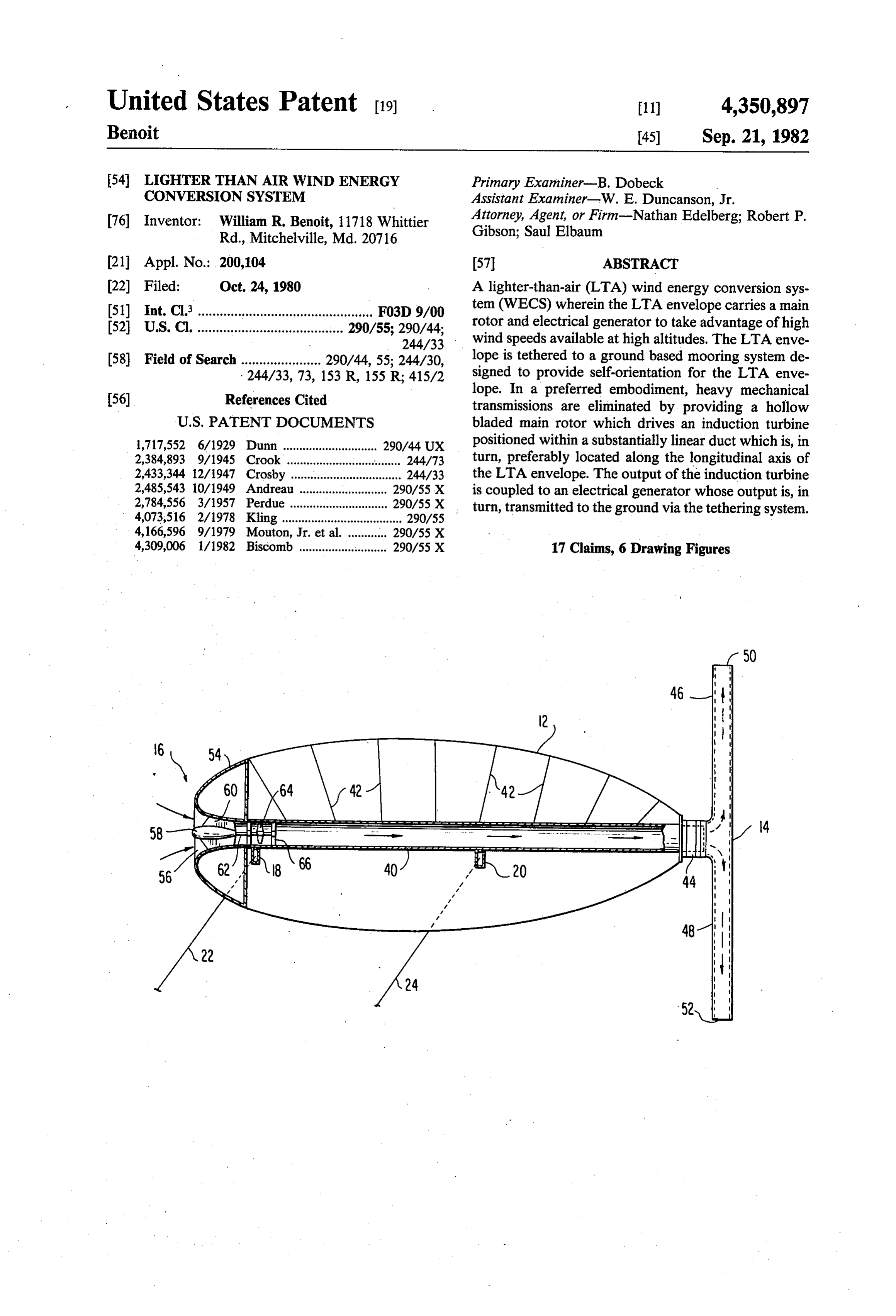
United States Patent (19) 11 4,350,897 Benoit 45) Sep. 21, 1982 54) LIGHTER THAN AIR WIND ENERGY Primary Examiner-B. Dobeck CONVERSION SYSTEM Assistant Examiner-W. E. Duncanson, Jr. 76) Inventor: William R. Benoit, 11718 Whittier Attorney, Agent, or Firm-Nathan Edelberg; Robert P. Rd., Mitchelville, Md. 20716 Gibson; Saul Elbaum 21 Appl. No.: 200,104 (57 ABSTRACT 22 Filed: Oct. 24, 1980 A lighter-than-air (LTA) wind energy conversion sys 51) Int. Cli................................................ F03D 9/00 tem (WECS) wherein the LTA envelope carries a main 52 U.S. C. ........................................ 290/55; 290/44; rotor and electrical generator to take advantage of high 244/33 wind speeds available at high altitudes. The LTA enve 58 Field of Search ...................... 290/44, 55; 244/30, lope is tethered to a ground based mooring system de 244/33, 73, 153 R, 155 R; 415/2 signed to provide self-orientation for the LTA enve lope. In a preferred embodiment, heavy mechanical 56) References Cited transmissions are eliminated by providing a hollow
1,717,552 6/1929 Dunn ....... ... 290/44 UX positioned within a substantially linear duct which is, in 2,384,893 9/1945 Crook ........................... so to 244/73 turn, preferably located along the longitudinal axis of 2,433,344 12/1947 Crosby .................................. 244/33 the LTA envelope. The output of the induction turbine 2,485,543 10/1949 Andreau ........................... 290/55 X is coupled to an electrical generator whose output is, in 2,784,556 3/1957 Perdue ........ ... 290/55 X turn, transmitted to the ground via the tethering system. 4,073,516 2/1978 Kling ..................................... 290/55 4,166,596 9/1979 Mouton, Jr. et al. ... 290/55 X 4,309,006 1/1982 Biscomb ........................... 290/55 X 17 Claims, 6 Drawing Figures
Page 2
Drawing sheet — no readable text.
Page 3
Drawing sheet — no readable text.
Page 4
ciency is that there is a requirement for an open ap
LIGHTER THAN AIR WIND ENERGY proach to the tower location, which leads to the desir CONVERSION SYSTEM ability of utilizing higher altitude, but relatively inacces RIGHTS OF THE GOVERNMENT sible, bald hills for placement of a WECS tower. Fur s ther, construction of a tower necessarily results in a
The invention described herein may be manufac fixed height for the main rotor whose electrical generat tured, used, and licensed by or for the U.S. Government ing capability is therefore at the mercy of the wind for governmental purposes without the payment to me density at that particular height at any given point in of any royalty thereon. time. Further, undesirable vibrations have been ob 10 served which result from what is referred to as "tower
BACKGROUND OF THE INVENTION shadow' which occurs when the blade of the rotor 1. Field of the Invention passes adjacent to the tower and sets up a type of vibra The present invention is related to wind energy con tory forcing function effect. Additionally, there are version systems and, more particularly, is directed inherent energy losses due to tower drag, and it is diffi towards a wind energy conversion system which is cult to erect, service and maintain the equipment posi carried aloft by a lighter-than-air structure. tioned on the top of the tower. 2. Description of the Prior Art Due to gravity loads, there presently exists a practical The advent of fossil fuel shortages has stimulated the maximum limit for the rotor diameter of approximately development of alternative energy sources, and in cer 300 feet. Further, a WECS having a 300 foot diameter tain regions of the world wind energy conversion sys-20 rotor tems (WECS) are becoming more efficient and compet ently that costs produces 2.5 megawatts of electricity pres approximately $3 million and includes a itive in generating large amounts of electricity for resi massive transmission, drive shaft and heavy bearings dential or commercial use. Commercial versions of a
WECS traditionally consist of a wind-driven rotor cou as complicate the towertodesign which add significantly the cost of the WECS as well pled to an electrical generator which are mounted on a 25 sive system must be positioned. upon For which such a mas example, a mechan tower to raise the large diameter rotor off the ground ical transmission required for a 300 foot diameter rotor and as high in the wind regime as possible, would weigh approximately 150-200 tons. The major challenges to a designer of a WECS are the dilute concentration of energy in the wind as well as tionalIn addition to the foregoing drawbacks, a conven the intermittent nature of the wind. The low power 30 like, toWECS requires yaw motors, bull rings and the turn the main rotor as the wind shifts direction density of wind dictates that WECS of large size are required if sizable amounts of electrical power are to be in order to maintain effective orientation. Such yaw generated. The intermittent nature of the wind nor motors and associated controls are expensive for large mally results in the rendering of a WECS in an idle state diameter rotors, are very slow to react, and add to much of the time. This has resulted in granting wind- 35 maintenance and servicing problems. generated electricity a value equal only to the fossil or There is a type of WECS which is known to obviate nuclear fuel displaced with relatively little value the need for a mechanical transmission. Such a WECS granted for the capital equipment. This has seriously is known in the art as an Enfield-Andreau wind machine retarded commercial WECS development. (see page 18 of “Wind Machines' by Frank R. Eldridge, In addition, since the wind spectrum contains gusts 40 The Mitre Corporation, October 1975). The Enfield and lulls, the stresses introduced into the rotor system of Andreau wind machine operates on a depression princi a WECS are large, and require rotor designs and sup ple wherein the blades of the propeller are hollow and port structures which are, to say the least, quite a chal are provided with apertures at their tips. Generally, the lenge to the designer. interior of the blades communicate through an air pas Since the power contained in the wind is a function of 45 sage in the hub of the propeller with the outlet of an air the cube of the velocity, the siting of a WECS becomes turbine which is coupled to an electric generator. When extremely important. Thus far, the best sites for a the wind velocity is of a value sufficient to cause rota ground-based WECS have been on the coastlines in the tion of the propeller, the air within the hollow blades is northern hemisphere, as well as on mountain tops and induced, by reason of the centrifugal force generated by hill tops. The latter elevations replace the high towers 50 its own mass, to flow out through the apertures in the required to position the wind-driven rotor high enough blade tips thereby forming a depression (i.e., a pressure to benefit from the velocity gradient of the wind. Un lower than that of the surrounding atmosphere) within fortunately, the availability of prime high-altitude sites the hollow blades. The air within the air turbine is then is severely limited, and although the cost of tower con at a higher pressure than that of the air remaining within struction is greatly reduced for such sites, the expenses 55 the blades, therefore establishing a continuous flow of of road building, transporting the heavy components air through the air turbine, the hub, the interiors of the and subsequent erection of the WECS are high. blades and out through the apertures at the tips. The It is generally considered that WECS must be placed flow of air through the air turbine supplies power to beyond the boundary layer portion of the wind in order drive the electric generator. A typical Enfield-Andreau to become inexpensive in terms of the energy yields. 60 WECS is set forth, for example, in U.S. Pat. No. Additionally, a WECS must be designed to afford maxi 2,784,556 to Perdue. Such a ground-based system, how mum protection against violent storms, which in the ever, still requires the propeller hub to be capable of past have been primarily responsible for wind machine rotation about a vertical axis in order that it may face breakdown or destruction. into the wind. Additionally, a conventional Enfield In addition to the inherent high cost attendant to the 65 Andreau WECS requires the incoming air to make at construction of a tower of sufficient height to position a least three 90' turns prior to expulsion through the large diameter (e.g., 300 foot) rotor, ground-based tow- . propeller tips. Such a system inherently loses energy ers suffer from several other deficiencies. One defi that it otherwise might have. Further, a ground-based
Page 5
Enfield-Andreau WECS suffers from the same defi much more efficient and hence more economical than ciency set forth above with respect to other WECS, prior art systems, which greatly reduces stresses in namely, the inability to take advantage of the high wind pinging on the rotor, and which is relatively easy to power densities found at considerable altitudes off the erect, maintain and service when compared to ground ground. based WECS.
I am also aware of U.S. Pat. No. 4,073,516 which An additional object of the present invention is to issued Feb. 14, 1978 to Kling. In this patent, the advan provide a wind energy conversion system which re tage of replacing a tower-based WECS with a gas-filled quires very little site preparation, has little impact on hollow body that carries a rotor assembly, current gen the environment, is virtually pollution-free, noise-free erator and alignment means is recognized. However, 10 and is visually unobjectionable.
the apparatus disclosed in this patent for accomplishing A further important object of the present invention is these noteworthy objectives are complex. Initially, the to provide an airborne wind energy conversion system system requires an alignment assembly for aligning the which eliminates the need for a mechanical transmission rotor to face into the wind, a ground anchor, and at least and thereby greatly reduces the weight of the system one captivating stay connecting the floating power 15 required to be airborne.
plant to the anchor. The support body is connected to Another important object of the present invention is the captivating stay through a joint connection requir to provide an LTA-WECS which can produce, for ing three degrees of freedom. The rotors are gimbal example, the same amount of electricity with a rotor of mounted at a variable relative position with respect to one-fourth the size of a ground-based WECS, or can the support body but in fixed positions relative to one 20 achieve four times the power as may be obtained for the another. Additionally, the rotor assembly requires at same size rotor on a tower-based WECS. least one pair of coaxially and coplanarly mounted The foregoing and other objects are attained in accor counter-rotating rotors having their moments of mo dance with one aspect of the present invention through mentum compensated. Again, while this patent does the provision of apparatus which comprises a lighter recognize the noteworthy advantage of elevating a 25 than-air structure and means supported by the lighter wind-driven power plane into high-altitude winds by than-air structure for generating electricity. Such means means of a lighter-than-air structure, the means for includes a main rotor adapted to be rotated by the wind, accomplishing same, it is felt, leaves much to be desired a turbine in fluid communication with the main rotor, and may be impractical. and an electrical generator coupled to the turbine. I am also aware of the following U.S. Patents which, 30 Means are preferably connected between the lighter together with the above-noted references, are consid than-air structure and the ground for tethering the ered by me to be the closest prior art to my invention: structure and for delivering electricity from the genera U.S. Pat. Nos. 1,717,552; 2,384,893; 2,433,344; and tor. -
3,936,652. In accordance with more specific aspects of the pres 35 ent invention, the main rotor includes at least one hol
OBJECTS AND SUMMARY OF THE low rotor blade having an air inlet and an air outlet. The INVENTION system further includes duct means for coupling the air It is therefore a primary object of the present inven inlet of the hollow rotor blade to the turbine, the latter tion to provide a wind energy conversion system preferably being positioned within the duct means. (WECS) which is coupled with a lighter-than-air More particularly, the duct means includes an open (LTA) structure for taking advantage of high energy front end and a rear end, the air inlet of the main rotor density winds at high altitudes in a more efficient and coupled to the rear end while the hollow rotor blade is economical manner than heretofore possible. adapted, upon rotation, to draw air through the open Another general object of the present invention is to front end of the duct means. The turbine preferably provide a wind energy conversion system which over 45 includes impeller blade means adapted to be rotated by comes the disadvantages and deficiencies noted above the air drawn through the open front end of the duct with respect to prior art WECS structures. means. The electrical generator may be positioned ei A further general object of the present invention is to ther forwardly or rearwardly of the turbine. provide a wind energy conversion system which totally The duct means preferably comprises a substantially eliminates the complications associated with ground 50 linear duct from the front end to the rear end thereof to based systems, including those associated with tower minimize air losses. In one embodiment, the duct is structure and cost. positioned within the lighter-than-air structure substan An additional object of the present invention is to tially along the longitudinal axis thereof. In this embodi provide a wind energy conversion system which per ment, the open front end of the duct comprises a ram air mits withdrawal of the system from the wind regime 55 inlet. Alternately, the duct may be positioned externally prior to the advent of a storm in order to protect the of the lighter-than-air structure, and in such a case system against damage. means may be provided for connecting the duct to the An additional object of the present invention is to structure, w
provide a WECS which may be positioned in any desir In a preferred embodiment, the main rotor is con able location, such as in a valley, off-shore, in marsh 60 nected to the rear of the lighter than air structure and land, and other locations heretofore thought inappro rotates in a plane which is substantially perpendicular to priate for an efficient WECS. the longitudinal axis of the structure. Another object of the present invention is to provide In accordance with other aspects of the present in a wind energy conversion system in combination with a vention, the means connected between the lighter-than lighter-than-air structure which is self-orienting, and 65 air structure and the ground preferably comprises at includes aerodynamic damping of orientation motions. least one tethering cable means and at least one electri An additional general object of the present invention cal cable means. Preferably provided on the ground are is to provide a wind energy conversion system which is means for mooring the cable means which includes
Page 6
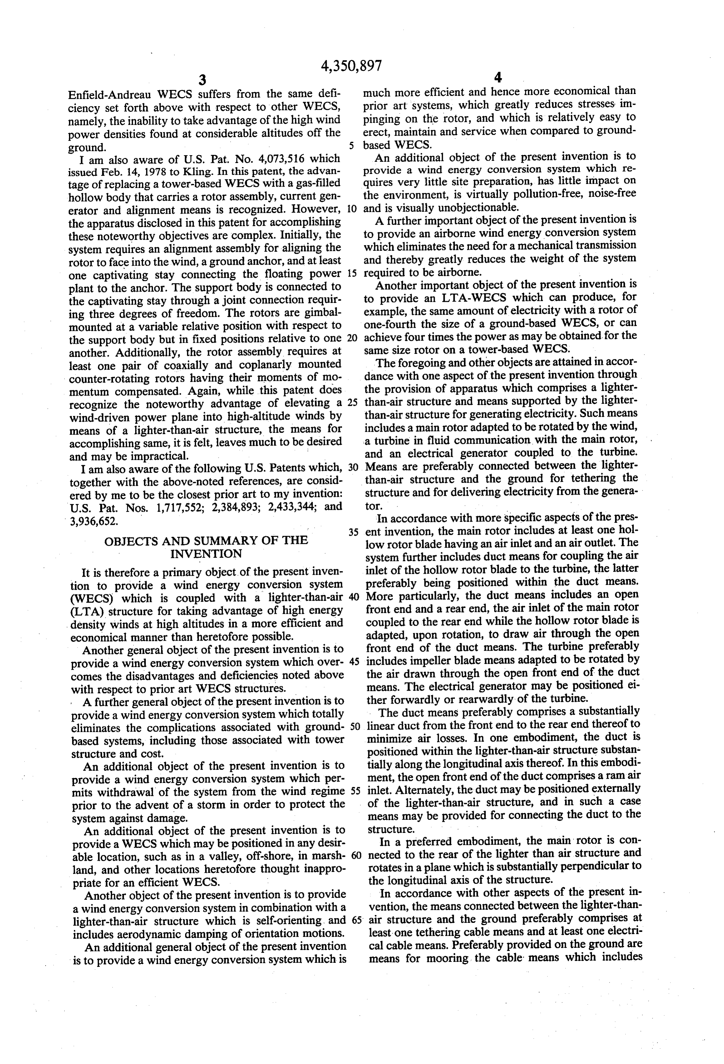
means for selectively drawing in the cable means and may be provided, as may be desirable. Excess lift pro thereby bringing the structure closer to the ground. vided by the LTA envelope 12 will keep tethering ca More particularly, the cable means may include at least bles 22 and 24 taut and the LTA envelope 12 in the two cables one of which is connected to the fore portion desired wind regime. While a single tethering cable may of the structure, the mooring means including a beam work as well, the double tethering arrangement illus which is pivotally coupled to a support pedestal and includes a cable connected preferably through a winch trated in FIG. 1 is preferred since it will maintain the LTA envelope 12 rigidly in a horizontal position as the to each end thereof. In the LTA-WECS, the cables are system 10 translates downwind and upwind. Preferably, connected to a pair of fore and aft outriggers that ex the LTA envelope 12 is designed with its center of lift tend laterally from the lighter-than-air structure. 10 co-located with its center of gravity, one of the tether BRIEF DESCRIPTION OF THE DRAWINGS ing cables such as 24 being attached just below the center of gravity. The cable tethering system illustrated
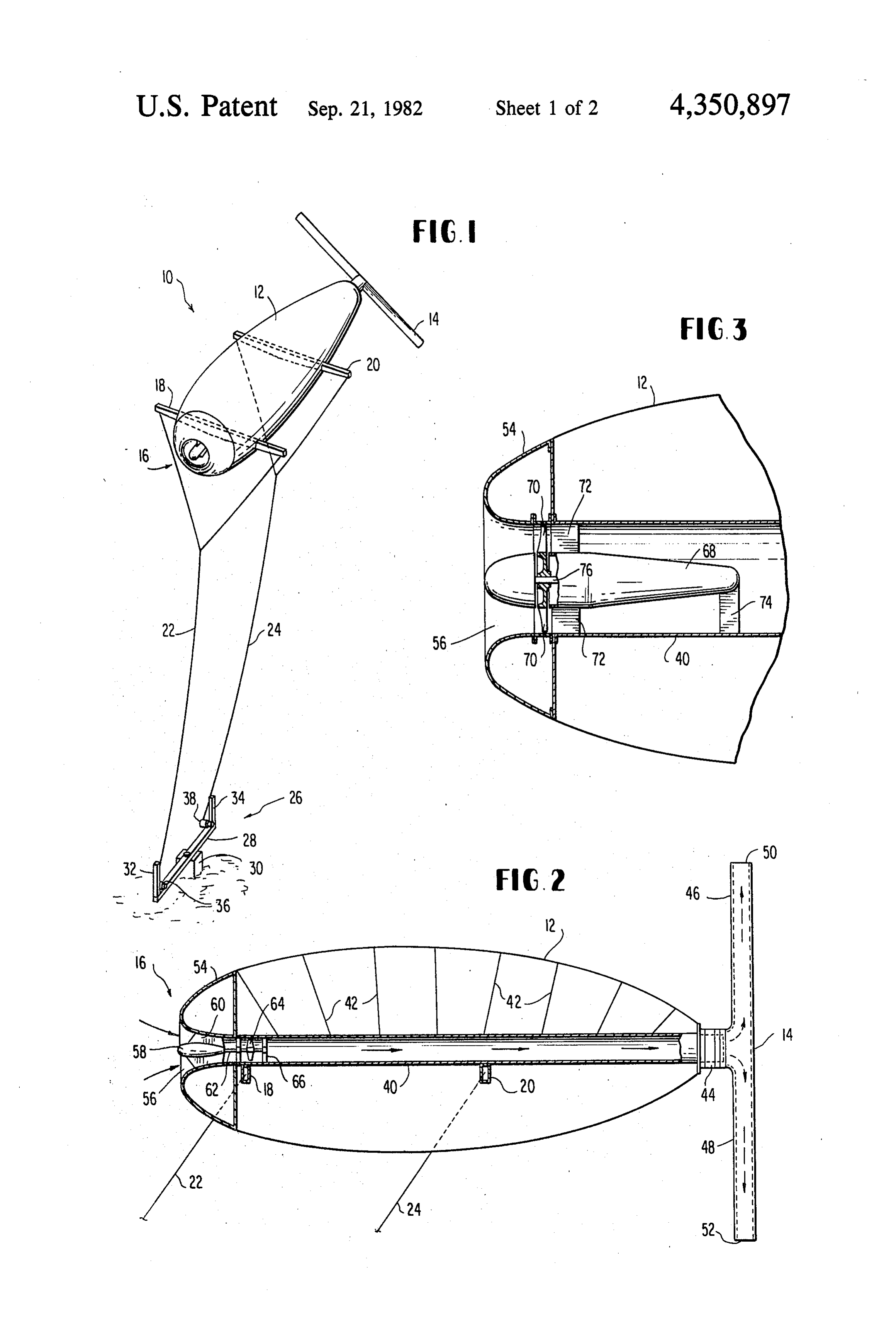
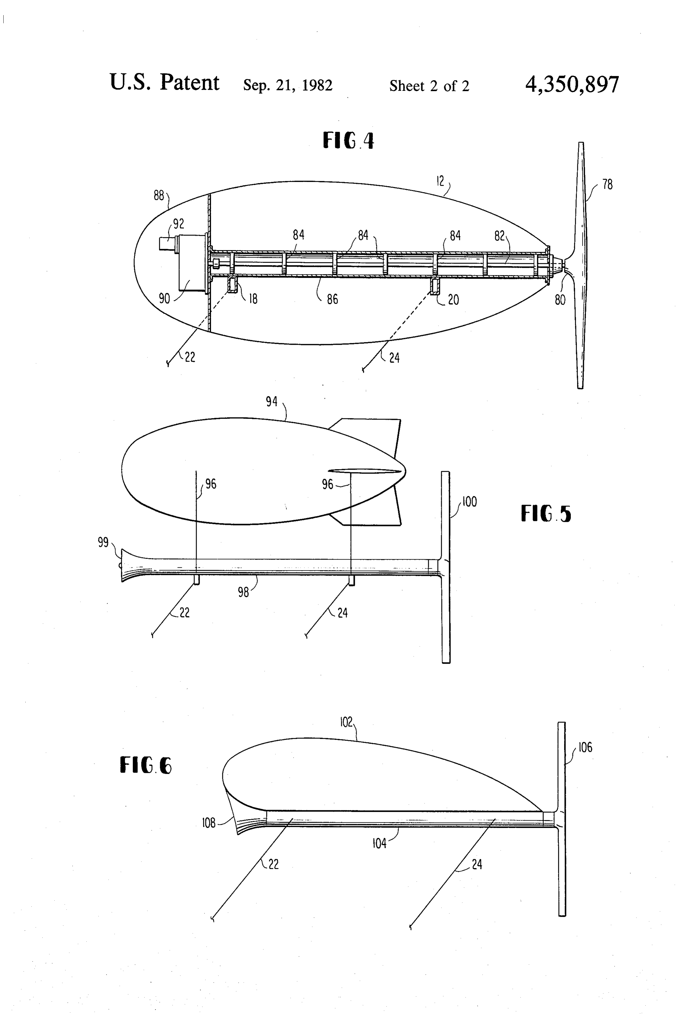
The foregoing and other objects, aspects, uses and in FIG. 1 allows the structure 12 to translate in the advantages of the present invention will become more downwind direction when impacted by a gust, thereby fully appreciated as the same becomes better under 15 relieving the stresses on the system 10. When the gust stood from the following detailed description of the expires and the lull begins, the restoring force from the present invention when considered in connection with lift vector of the envelope 12 will translate the vehicle the accompanying drawings, in which: into the wind thereby regaining the energy of the gust. FIG. 1 is a perspective view of a preferred embodi This feature results in a smoothing of the velocity pro ment of the present invention; 20 file of the wind and, therefore, dramatically smooths the FIG.2 is a longitudinal sectional view of the lighter stresses or loads on the rotor 14.
than-air structure of FIG. 1; The lower ends of the tethering cables 22 and 24 are FIG. 3 is an enlarged, broken sectional view of the secured to a mooring system which is indicated gener forward portion of an alternate embodiment to that ally by reference numeral 26. Although the mooring illustrated in FIG. 2; 25 system 26 could take any of a number of forms, in the . FIG. 4 is a view similar to FIG. 2 but illustrating yet preferred embodiment, the mooring system 26 includes another alternate embodiment; an elongated beam 28 which is pivotally coupled at its FIG. 5 is a schematic representation of yet a further center point to a support pedestal 30 (e.g., concrete) alternate embodiment of the present invention; and which is affixed in the ground. A pair of mooring stan FIG. 6 is a schematic representation of still another 30 chions 32 and 34 are provided at the ends of beam 28 to alternate embodiment of the present invention. permit the LTA envelope 12 to be secured during bad DETAILED DESCRIPTION OF THE weather. For this purpose, a pair of winches 36 and 38, PREFERRED EMBODIMENTS or the like, may be provided for drawing in cables 22 and 24, respectively.
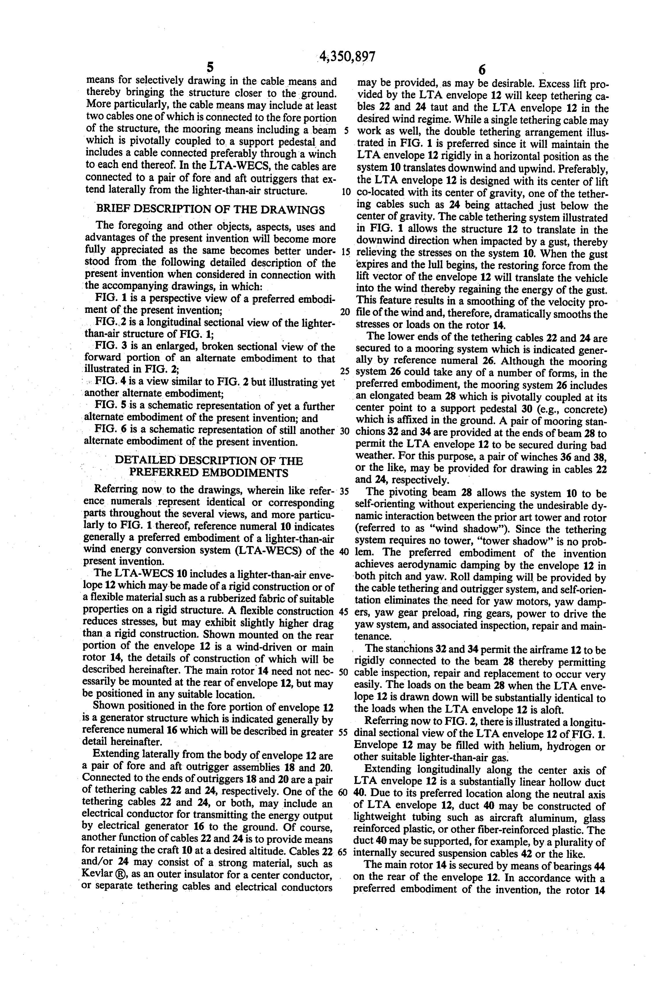
Referring now to the drawings, wherein like refer 35 The pivoting beam 28 allows the system 10 to be ence numerals represent identical or corresponding self-orienting without experiencing the undesirable dy parts throughout the several views, and more particu namic interaction between the prior art tower and rotor larly to FIG. 1 thereof, reference numeral 10 indicates (referred to as "wind shadow"). Since the tethering generally a preferred embodiment of a lighter-than-air system requires no tower, "tower shadow' is no prob wind energy conversion system (LTA-WECS) of the lem. The preferred embodiment of the invention present invention. achieves aerodynamic damping by the envelope 12 in The LTA-WECS 10 includes a lighter-than-air enve both pitch and yaw. Roll damping will be provided by lope 12 which may be made of a rigid construction or of the cable tethering and outrigger system, and self-orien a flexible material such as a rubberized fabric of suitable tation eliminates the need for yaw motors, yaw damp properties on a rigid structure. A flexible construction 45 ers, yaw gear preload, ring gears, power to drive the reduces stresses, but may exhibit slightly higher drag yaw system, and associated inspection, repair and main than a rigid construction. Shown mounted on the rear tenance.
portion of the envelope 12 is a wind-driven or main The stanchions 32 and 34 permit the airframe 12 to be rotor 14, the details of construction of which will be rigidly connected to the beam 28 thereby permitting described hereinafter. The main rotor 14 need not nec 50 cable inspection, repair and replacement to occur very essarily be mounted at the rear of envelope 12, but may easily. The loads on the beam 28 when the LTA enve be positioned in any suitable location. lope 12 is drawn down will be substantially identical to Shown positioned in the fore portion of envelope 12 the loads when the LTA envelope 12 is aloft. is a generator structure which is indicated generally by Referring now to FIG. 2, there is illustrated a longitu reference numeral 16 which will be described in greater 55 dinal sectional view of the LTA envelope 12 of FIG. 1. detail hereinafter. Envelope 12 may be filled with helium, hydrogen or Extending laterally from the body of envelope 12 are other suitable lighter-than-air gas.
a pair of fore and aft outrigger assemblies 18 and 20. Extending longitudinally along the center axis of Connected to the ends of outriggers 18 and 20 are a pair LTA envelope 12 is a substantially linear hollow duct of tethering cables 22 and 24, respectively. One of the 40. Due to its preferred location along the neutral axis tethering cables 22 and 24, or both, may include an electrical conductor for transmitting the energy output of LTA envelope 12, duct 40 may be constructed of lightweight tubing such as aircraft aluminum, glass by electrical generator 16 to the ground. Of course, reinforced plastic, or other fiber-reinforced plastic. The another function of cables 22 and 24 is to provide means duct 40 may be supported, for example, by a plurality of for retaining the craft 10 at a desired altitude. Cables 22 65 internally secured suspension cables 42 or the like. and/or 24 may consist of a strong material, such as The main rotor 14 is secured by means of bearings 44 Kevlar (R), as an outer insulator for a center conductor, on the rear of the envelope 12. In accordance with a or separate tethering cables and electrical conductors preferred embodiment of the invention, the rotor 14
Page 7
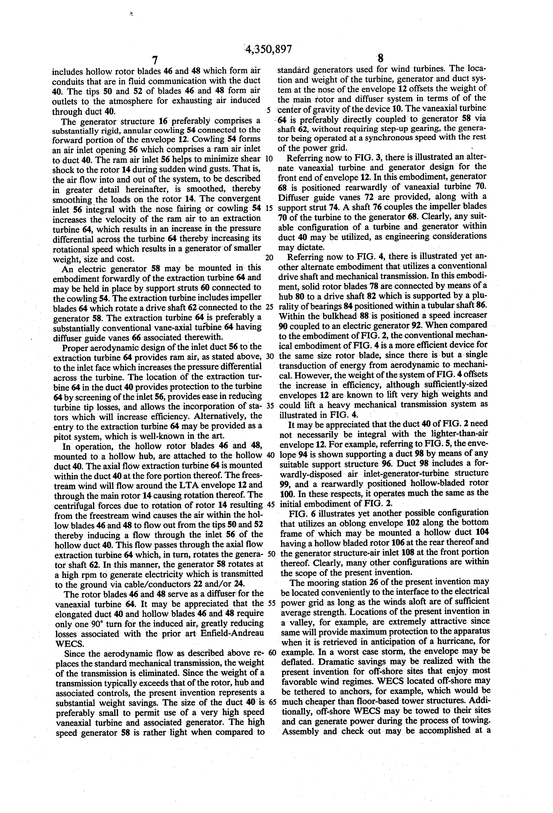
includes hollow rotor blades 46 and 48 which form air standard generators used for wind turbines. The loca conduits that are in fluid communication with the duct tion and weight of the turbine, generator and duct sys 40. The tips 50 and 52 of blades 46 and 48 form air tem at the nose of the envelope 12 offsets the weight of outlets to the atmosphere for exhausting air induced the main rotor and diffuser system in terms of of the through duct 40. center of gravity of the device 10. The vaneaxial turbine The generator structure 16 preferably comprises a 64 is preferably directly coupled to generator 58 via substantially rigid, annular cowling 54 connected to the shaft 62, without requiring step-up gearing, the genera forward portion of the envelope 12. Cowling 54 forms tor being operated at a synchronous speed with the rest an air inlet opening 56 which comprises a ram air inlet of the power grid.
to duct 40. The ram air inlet 56 helps to minimize shear O Referring now to FIG. 3, there is illustrated an alter shock to the rotor 14 during sudden wind gusts. That is, nate vaneaxial turbine and generator design for the the air flow into and out of the system, to be described 68 front end of envelope 12. In this embodiment, generator in greater detail hereinafter, is smoothed, thereby is positioned rearwardly of vaneaxial turbine 70. smoothing the loads on the rotor 14. The convergent 15 Diffuser guide vanes 72 are provided, along with a inlet 56 integral with the nose fairing or cowling 54 support strut 74. A shaft 76 couples the impeller blades increases the velocity of the ram air to an extraction 70 of the turbine to the generator 68. Clearly, any suit turbine 64, which results in an increase in the pressure able configuration of a turbine and generator within differential across the turbine 64 thereby increasing its duct 40 may be utilized, as engineering considerations rotational speed which results in a generator of smaller may dictate.
weight, size and cost. 20 Referring now to FIG. 4, there is illustrated yet an An electric generator 58 may be mounted in this other alternate embodiment that utilizes a conventional embodiment forwardly of the extraction turbine 64 and drive shaft and mechanical transmission. In this embodi may be held in place by support struts 60 connected to ment, solid rotor blades 78 are connected by means of a the cowling 54. The extraction turbine includes impeller hub 80 to a drive shaft 82 which is supported by a plu blades 64 which rotate a drive shaft 62 connected to the 25 rality of bearings 84 positioned within a tubular shaft 86. generator 58. The extraction turbine 64 is preferably a Within the bulkhead 88 is positioned a speed increaser substantially conventional vane-axial turbine 64 having 90 coupled to an electric generator 92. When compared . diffuser guide vanes 66 associated therewith. to the embodiment of FIG. 2, the conventional mechan Proper aerodynamic design of the inlet duct 56 to the ical embodiment of FIG. 4 is a more efficient device for extraction turbine 64 provides ram air, as stated above, 30 the same size rotor blade, since there is but a single to the inlet face which increases the pressure differential transduction of energy from aerodynamic to mechani across the turbine. The location of the extraction tur cal. However, the weight of the system of FIG. 4 offsets the increase in efficiency, although sufficiently-sized bine 64 in the duct 40 provides protection to the turbine envelopes 64 by screening of the inlet 56, provides ease in reducing 12 are known to lift very high weights and turbine tip losses, and allows the incorporation of sta 35 could lift a heavy mechanical transmission system as tors which will increase efficiency. Alternatively, the illustrated in FIG. 4.
entry to the extraction turbine 64 may be provided as a It may be appreciated that the duct 40 of FIG. 2 need pitot system, which is well-known in the art. not necessarily be integral with the lighter-than-air In operation, the hollow rotor blades 46 and 48, envelope 12. For example, referring to FIG. 5, the enve mounted to a hollow hub, are attached to the hollow lope 94 is shown supporting a duct 98 by means of any duct 40. The axial flow extraction turbine 64 is mounted suitable support structure 96. Duct 98 includes a for within the duct 40 at the fore portion thereof. The frees wardly-disposed air inlet-generator-turbine structure tream wind will flow around the LTA envelope 12 and 99, and a rearwardly positioned hollow-bladed rotor through the main rotor 14 causing rotation thereof. The 100. In these respects, it operates much the same as the centrifugal forces due to rotation of rotor 14 resulting 45 initial embodiment of FIG. 2.
from the freestream wind causes the air within the hol FIG. 6 illustrates yet another possible configuration low blades 46 and 48 to flow out from the tips 50 and 52 that utilizes an oblong envelope 102 along the bottom thereby inducing a flow through the inlet 56 of the frame of which may be mounted a hollow duct 104 hollow duct 40. This flow passes through the axial flow having a hollow bladed rotor 106 at the rear thereof and extraction turbine 64 which, in turn, rotates the genera 50 the generator structure-air inlet 108 at the front portion tor shaft 62. In this manner, the generator 58 rotates at thereof. Clearly, many other configurations are within a high rpm to generate electricity which is transmitted the scope of the present invention. to the ground via cable/conductors 22 and/or 24. The mooring station 26 of the present invention may The rotor blades 46 and 48 serve as a diffuser for the be located conveniently to the interface to the electrical vaneaxial turbine 64. It may be appreciated that the 55 power grid as long as the winds aloft are of sufficient elongated duct 40 and hollow blades 46 and 48 require average strength. Locations of the present invention in only one 90' turn for the induced air, greatly reducing a valley, for example, are extremely attractive since losses associated with the prior art Enfield-Andreau same will provide maximum protection to the apparatus WECS. when it is retrieved in anticipation of a hurricane, for Since the aerodynamic flow as described above re example. In a worst case storm, the envelope may be deflated. Dramatic savings may be realized with the places the standard mechanical transmission, the weight present of the transmission is eliminated. Since the weight of a invention for off-shore sites that enjoy most transmission typically exceeds that of the rotor, hub and favorable wind regimes. WECS located off-shore may associated controls, the present invention represents a be tethered to anchors, for example, which would be substantial weight savings. The size of the duct 40 is 65 much cheaper than floor-based tower structures. Addi preferably small to permit use of a very high speed tionally, off-shore WECS may be towed to their sites vaneaxial turbine and associated generator. The high and can generate power during the process of towing. speed generator 58 is rather light when compared to Assembly and check out may be accomplished at a
Page 8
shore station prior to towing. Additionally, mainte said air inlet of said hollow rotor blade coupled to said nance, repair and modification may be done at the shore rear end, said hollow rotor blade adapted, upon rotation base. Clearly, the design of the present invention will thereof, to draw air through said open front end. not require structure to oppose the fury of sea waves 6. The apparatus as set forth in claim 5, wherein said during storms. 5 turbine includes impeller blade means adapted to be Environmentally, it is by now appreciated that wind rotated by the air drawn through said open front end of mills are non-polluting devices that, if reasonably effi said duct means.
cient, can greatly assist the energy situation. Although 7. The apparatus as set forth in claim 6, wherein said the present invention is quiet compared to other me electrical generator is positioned forwardly of said tur chanical equipment, the device may be placed high 10 bine.
enough so that it would be soundless to personnel on the 8. The apparatus as set forth in claim 6, wherein said ground. Aesthetically, the invention is a dramatic im electrical generator is positioned rearwardly of said provement over conventional ground-based machines. turbine within said duct means. The high altitudes and thin cables render a degree of 9. The apparatus as set forth in claim 6, wherein said near invisibility for personnel at the mooring site, and a 15 duct means comprises a substantially linear duct from reduction in apparent size for distant observers. said front end to said rear end thereof. It may be appreciated that the present invention pro 10. The apparatus as set forth in claims 3, 5 or 9, vides many solutions to the disadvantages and deficien wherein said duct is positioned within said lighter than cies of the prior art WECS. Since the surface-to-volume air structure ratio of gas envelopes becomes more favorable with 20 said structure.substantially along the longitudinal axis of increased size, and because wind rotors become cheaper per square foot of swept area with increased size, an said11.open The apparatus as set forth in claim 10, wherein front end of said duct comprises a ram air economical WECS according to the present invention inlet.
will be quite large. For example, it is estimated that 12. The apparatus as set forth in claims 3, 5 or 9, machines having 200 foot rotor diameters are feasible. 25 wherein
Much larger sizes, capable of generating 10 megawatts, than air said duct is positioned externally of said lighter structure, and further comprising means for may also be achieved. connecting said duct to said structure. Obviously, numerous modifications and variations of the present invention are possible in light of the above wherein13. The apparatus as set forth in claims 1, 6 or 9, teachings. It is therefore to be understood that within 30 said main rotor is connected to the rear of said the scope of the appended claims, the invention may be lighter than air structure and rotates in a plane which is substantially perpendicular to the longitudinal axis of practiced otherwise than as specifically described said structure.
herein.
I claim as my invention: 14. The apparatus as set forth in claims 1, 5 or 9, 1. Apparatus, which comprises: 35 wherein said means connected between said lighter than a lighter than air structure; air structure and the ground comprises at least one means supported by said lighter than air structure for tethering cable means and at least one electrical cable generating electricity, said means including a main aS rotor adapted to be rotated by the wind, a turbine 15. The apparatus as set forth in claim 14, further in fluid communication with said main rotor, and 40 comprising means positioned on the ground for moor an electrical generator coupled to said turbine; and ing said cable means which includes means for selec means connected between said lighter than air struc tively drawing in said cable means and thereby bringing ture and the ground for tethering said structure and said structure closer to the ground.
for delivering electricity from said generator. 16. The apparatus as set forth in claim 15, wherein 2. The apparatus as set forth in claim 1, wherein said 45 said cable means includes at least two cables, one of main rotor includes a hollow rotor blade having an air which is connected to the fore portion of said structure, inlet and an air outlet. said mooring means including a beam pivotally coupled 3. The apparatus as set forth in claim 2, further com to a support pedestal and having one of said cables prising duct means for coupling said air inlet of said connected to each end thereof.
hollow rotor blade to said turbine. 50 17. The apparatus as set forth in claim 16, further 4. The apparatus as set forth in claim 3, wherein said comprising outriggers extending laterally from said turbine is positioned within said duct means. lighter than air structure to which said cables are con 5. The apparatus as set forth in claim 4, wherein said nected.
duct means includes an open front end and a rear end, e
Provenance
- Collection
- Cited prior art
- Original PDF
- patentimages.storage.googleapis.com →
- Filed
- 1980-10-24
- Pages
- 8
- Method
- pdftotext (the PDF's own text layer) + pdftoppm 300dpi page scans
- Source
- Google Patents bibliographic record
- Granted
- 1982-09-21
- Inventors
- William R. Benoit
- Transcribed from
- patentimages.storage.googleapis.com →