patent · US4906060
Apparatus and method for controlling the output frequency of a wind-driven alternator
6 March 1990
Page 1 — bibliographic record
United States Patent (19) 11 Patent Number: 4,906,060 Claude 45 Date of Patent: Mar. 6, 1990 54 APPARATUS AND METHOD FOR 4,656,413 4/1987 Bourbeau .......................... 322/35 X CONTROLLING THE OUTPUTFREQUENCY Primary Examiner-R. J. Hickey
OF A WIND-DRIVEN ALTERNATOR Attorney, Agent, or Firm-Dennis T. Griggs (75) Inventor: David L. Claude, Justin, Tex. 57 ABSTRACT 73 Assignee: Twind Energy Corporation, Method and apparatus for controlling the output fre Ridgewood, N.J. quency of an alternator by maintaining a relatively (21) Appl. No.: 327,823 constant speed of rotation of the alternator rotor are disclosed. The rotor includes an annular stator and a 22 Filed: Mar. 23, 1989 rotor rotatably mounted within. In one embodiment the 51) Int. Cl* ........................ H02K 29/00; H02P 9/00 stator winding is comprised of a plurality of discrete 52 U.S. C. ........................................ 322/29; 322/32; polyphase windings positioned within discrete annular 322/93; 290/44; 310/200; 318/.502 segments of the stator. When the actual rotor speed is 58 Field of Search ....................... 322/10, 11, 29, 32, below the desired speed, selected stator units are de 322/40, 89,90, 93,35; 290/44, 55; 318/.502, energized to decrease the strength of the stator mag 369,379; 310/200 netic field, thereby permitting the rotor speed to in (56) References Cited crease. When the actual rotor speed is greater than the
increase the strength of the stator magnetic field, 3,121,838 2/1964 Mozic ............................... 322/90 X thereby exerting a braking force on the rotor to slow it 3,200,324 8/1965 Wagner ................................. 322/32 down. In another embodiment each phase of the poly 3,404,326 10/1968 Repke ............................... 322/90 X phase stator winding includes a plurality of inductor 3,694,731 9/1972 Cherry .............................. 322/29 X 3,740,565 6/1973 Wesley .................................. 290/55 coils. Selected ones of the coils in each phase of the 4,059,771 11/1977 Jacobs et al. ... 290/44 stator winding are selectively energized to decrease the 4,395,669 7/1983 Berna et al... ... 318/.502 rotor speed or de-energized to increase the rotor speed, 4,419,618 12/1983 Gretsch ............ ... 322/29 X as required to maintain the desired rotor speed for sub 4,510,433 4/1985 Gamze et al. ......................... 322/32 stantially constant frequency output. 4,511,807 4/1985 Somerville ............................ 290/44 4,585,950 4/1986 Lund ..................................... 290/44 4,642,547 2/1987 Redlich ............................. 322/93 X 21 Claims, 3 Drawing Sheets
POWER OUTPUt
disc
60 Hz. REF
Page 2
Drawing sheet — no readable text.
Page 3
Drawing sheet — no readable text.
Page 4
Drawing sheet — no readable text.
Page 5
in a wind-driven generator. One such system uses a
APPARATUS AND METHOD FOR CONTROLLING speed control device which switches load resistors in THE OUTPUT FREQUENCY OF A WIND-DRIVEN and out of the output electrical circuit to maintain a ALTERNATOR relatively constant rotor speed, substantially indepen dently of variations in wind speed. Still other systems
FIELD OF THE INVENTION use relatively complex circuitry for controlling the The present invention relates generally to polyphasecurrent excitation applied to the stator windings to dynamoelectric machines, and in particular to a wind achieve the desired output characteristics of the genera driven alternator, the output frequency of which is O tor. In one such system the position of the rotor with proportional to the rotational speed of the alternator respect to the stator at any given time is detected by rotor. optical sensors. A microprocessor is used to transmit BACKGROUND OF THE INVENTION timed control signals to selectively conduct current through the stator winding at predetermined times. This
Electrical generators convert mechanical energy into system requires complex electro-optical devices in electrical energy by rotating an electrical conductor 15 order to control the excitation of the stator winding. (rotor) with respect to a relatively stationary magnetic element (stator), which produces an electric current in OBJECTS OF THE INVENTION the rotor. Rotational motion may be imparted to the It is, therefore, the principal object of the present rotor by a variety of means, such as an electric motor, 20 invention to provide an improved apparatus and wind turbine or the like. Electrical generators can be method for maintaining a substantially, constant rotor used to generate both DC and AC current. Within the class of AC current generators, also known as alterna speed and output frequency in an electrical alternator. Another object of the invention is to provide an im tors, is the so-called "polyphase' AC generator, in proved system which both the stator and rotor are equipped with poly tion of selectedand method for controlling the excita portions of the stator winding in an phase electrically conductive windings. 25
The output frequency of an alternator is proportional alternator.
Still another object of the invention is to provide an to the speed of rotation (RPM) of the rotor. For exam improved system and method for controlling the rota ple, a three phase AC generator may require a rotor speed of 1800 RPM to generate a 60 Hz AC signal. tional speed of a wind-driven generator, substantially Some electrical equipment which operates on AC cur 30 independently of variations in wind speed. rent requires constant frequency (e.g. 60 Hz) for effi A further object of the invention is to provide a rela cient operation. It is therefore critical to maintain a tively simple and economical apparatus and method for substantially constant rotor speed for constant fre maintaining a constant rotor speed and output fre quency output. It is also critical to maintain a constant quency in an electrical alternator. rotor speed to reduce wear and tear on mechanical 35 SUMMARY OF THE INVENTION components and for optimum operating efficiency of the machine. Machinery, such as electrical generators, The present invention is designed for use in a wind are dynamically balanced to run most efficiently at one driven alternator to produce 60 Hz power output at or more selected speeds of rotation. variable wind speeds substantially below the conven Wind-driven propellers or turbines are often used to tional threshold of twelve miles per hour. supply mechanical energy to turn the alternator rotor. This is accomplished by a wind-driven alternator in One problem associated with such wind-driven ma which three-phase, 60Hz power is delivered by a three chines is that wind speed variations will produce corre phase wound rotor which rotates within a three-phase sponding variations in the rotor speed and output fre field produced by an articulated stator. The stator is quency unless the rotor speed is otherwise regulated. 45 "articulated' in the sense that multiple stator units are DESCRIPTION OF THE PRIOR ART physically stacked and are wound separately, so that the Conventional wind-driven alternators have a three magnetomotive force contribution of each stator can be added to the total electromotive force which produces phase, wound rotor which constitutes the field. The the electromagnetic stator is also wound in three phase and delivers the SO coupled to the three-phase stator field which is magnetically output current. Such wind-driven alternators are de wound rotor. signed, typically, to drop offline when wind speeds fall sired level, one or more statorspeed Accordingly, when wind units drops below a de can be de-energized below a certain threshold level, for example twelve by disconnecting their separate windings, with field miles per hour. The reason for this is that the mechani excitation being applied only to the separate stator cal governor cannot reliably maintain 1800 RPM below 55 windings which remain energized. The overall mag the threshold wind speed level, assuming average netic field produced by the separate stator windings power loading. A constant 1800 RPM rotor speed is essential for the generation of output power at 60 Hz, appears as a mechanical load upon the wound rotor, which is the standard power frequency in the United thus imposing a magnetic braking force upon the rotor States. Although the rotor will continue turning at shaft.
lower speeds, and will produce power at such lower If all stator units are disconnected, there is no mag speeds, the frequency of the output current will drop netic brake effect, with only bearing frictional loads below the standard 60 Hz, so that legally, it cannot be tending to limit rotor speed. The power output, how applied to domestic subscriber loads, and technically it ever, is directly proportional to the number of stator could cause malfunctioning of loads such as electric 65 units which are connected into the field excitation cir motors which are intended to be operated at 60 Hz. cuit. The compromise of trade-off effected by this sys There are a variety of systems and methods known in tem is a reduction of power output to maintain a con the art for maintaining a relatively constant rotor speed stant RPM on the rotor shaft, which will produce a
Page 6
usable, 60 Hz power output, although it will be at a selected ones of the coils in each phase of the stator lower output level. winding to decrease the strength of the stator magnetic According to one aspect of the invention, the three field.
phase field excitation is determined by the magnitude of In the preferred embodiment a tachometer is attached the rotor shaft RPM. An analog signal is developed by 5 to the rotor for measuring the rotational speed thereof an RPM sensor coupled to the rotor shaft. This signal is and for generating an analog signal indicative of the compared with a 60 Hz reference signal. rotor speed at any given time. This analog speed signal, The load control logic circuit evaluates the magni together with an analog reference signal indicative of tude of the difference and generates a digital data word which corresponds with a unique, parallel combination 10 the desired speed of rotation of the rotor, is fed into an analog comparator. The amplitudes of the two signals of separate stator units for receiving the three-phase are compared and the comparator generates an analog field excitation. Three-phase field excitation is applied signal indicative of the differential amplitude between to various combinations of stator windings through the the address decoder/driver. According to this arrange speedtwoexceeds input signals. For example, if the actual rotor the desired speed, the comparator will ment, the magnetic brake effect imposed by stator load 15 generate a positive analog signal, the amplitude of ing is automatically reduced and increased in steps, as which rotor RPM decreases and increases with respect to a tual rotor speed exceedsto the is proportional the amount by which the ac desired rotor speed. If, on predetermined threshold level. the other hand, the actual rotor speed is less than the In an alternative embodiment, the stator is not articu lated, but each phase group of the stator winding com desired rotor speed, the comparator will generate a prises multiple winding coils which are circumferen negative signal, the amplitude of which is proportional tially spaced about a unitary stator core. Each winding to the amount by which the actual rotor speed is less coil within each phase group includes one or more than the desired rotor speed.
turns, with the end turn portions of each coil being The output of the comparator is fed into an analog-to brought out at the end of the stator core. The coils of 25 digital converter, wherein the amplitude differential is each phase group are separately energized so that the converted to a digital amplitude signal. Encoding cir effective number of coil turns within each phase group cuitry is provided for converting the digital amplitude can be increased or decreased incrementally. For exam signals into corresponding control signals, each of ple, in a stator core having 36 slots, each phase group which contains a discreté digital code representing the comprises 12 separate coils, with each coil having multi 30 selected portion of the stator winding which is to be ple turns. As an additional coil is connected or discon enabled or disabled, as the case may be. Driver means, nected, the magnetomotive force contribution is in which is preferably comprised of a decoder and a creased or decreased by about eight percent. switching circuit, is responsive to the control signals for The apparatus according to the present invention is selectively applying an excitation signal to selected comprised of means for measuring the rotational speed 35 portions of the stator winding in response to a first set of of the rotor and for generating a first electrical signal control signals indicating that selected portions of the indicative thereof; means for generating a second elec stator winding are to be energized and for disabling the trical signal representing a desired rotational speed of excitation signal from being applied to selected portions the rotor corresponding to a desired output frequency of the stator winding in response to a second set of of the alternator; means for comparing the first and 40 control signals indicating that selected portions of the second electrical signals and for generating a third elec stator winding are to be de-energized. trical signal when actual rotor speed is greater than The apparatus and method according to the present desired rotor speed and for generating a fourth electri invention provide a relatively simple and economical cal signal when the actual rotor speed is less than the technique for maintaining a substantially constant out desired rotor speed; and control means responsive to 45 put frequency in an electrical alternator by controlling the third electrical signal for enabling selected portions the rotor speed. The invention is particularly suitable of the stator winding, thereby increasing the strength of for use in connection with an alternator which is me the stator magnetic field to decrease the rotational speed of the rotor and to the fourth electrical signal for chanically to compensate coupled to a wind turbine or the like in order for variations in the wind speed.
disabling selected portions of the stator winding to 50 decrease the strength of the stator magnetic field and BRIEF DESCRIPTION OF THE DRAWINGS increase the rotational speed of the rotor. Other objects and advantages of the invention will be In one embodiment the stator includes a plurality of apparent from the detailed description and claims when discrete stator windings disposed on discrete annular read in conjunction with the accompanying drawings segments of the stator. The control means is responsive 55 wherein:
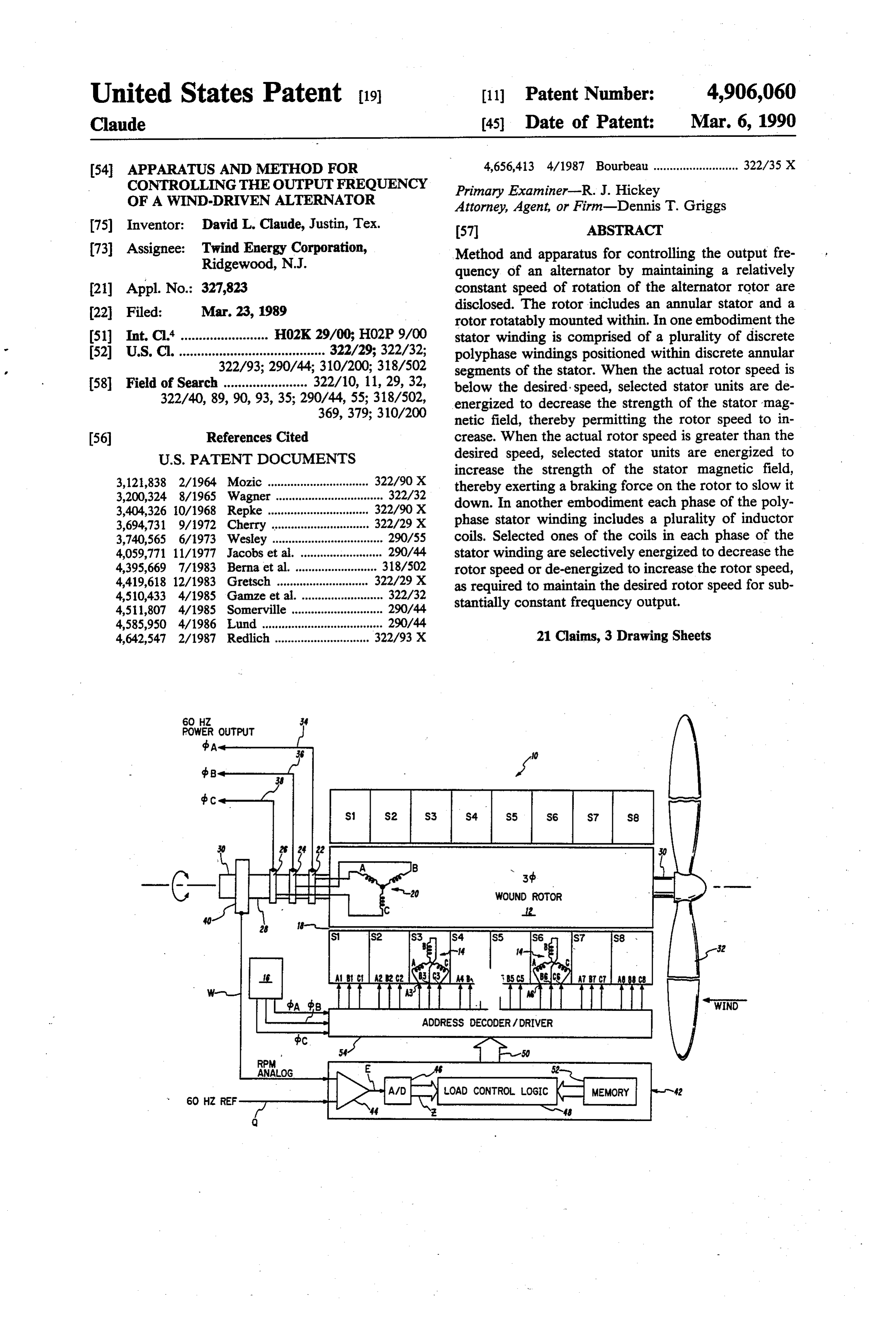
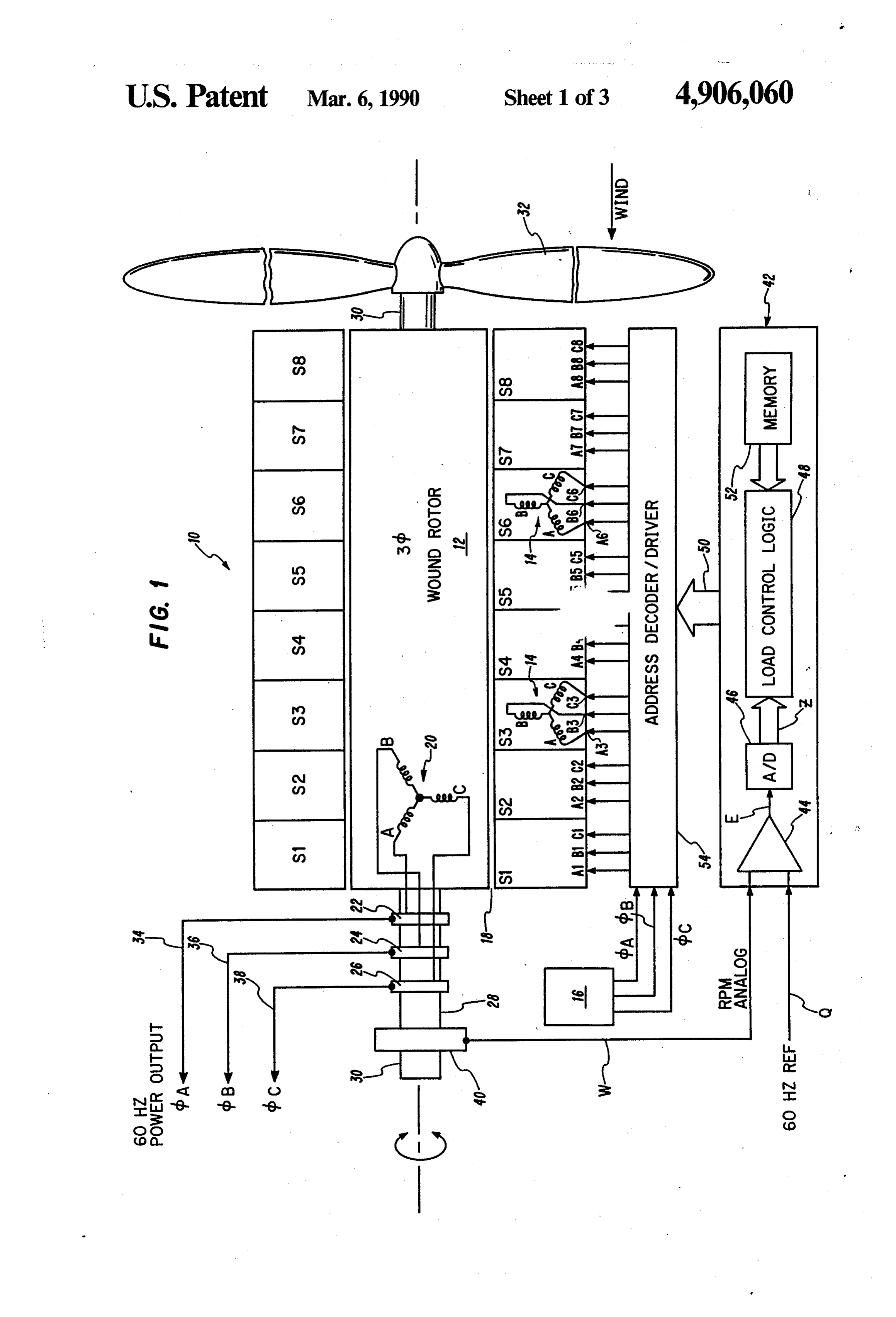
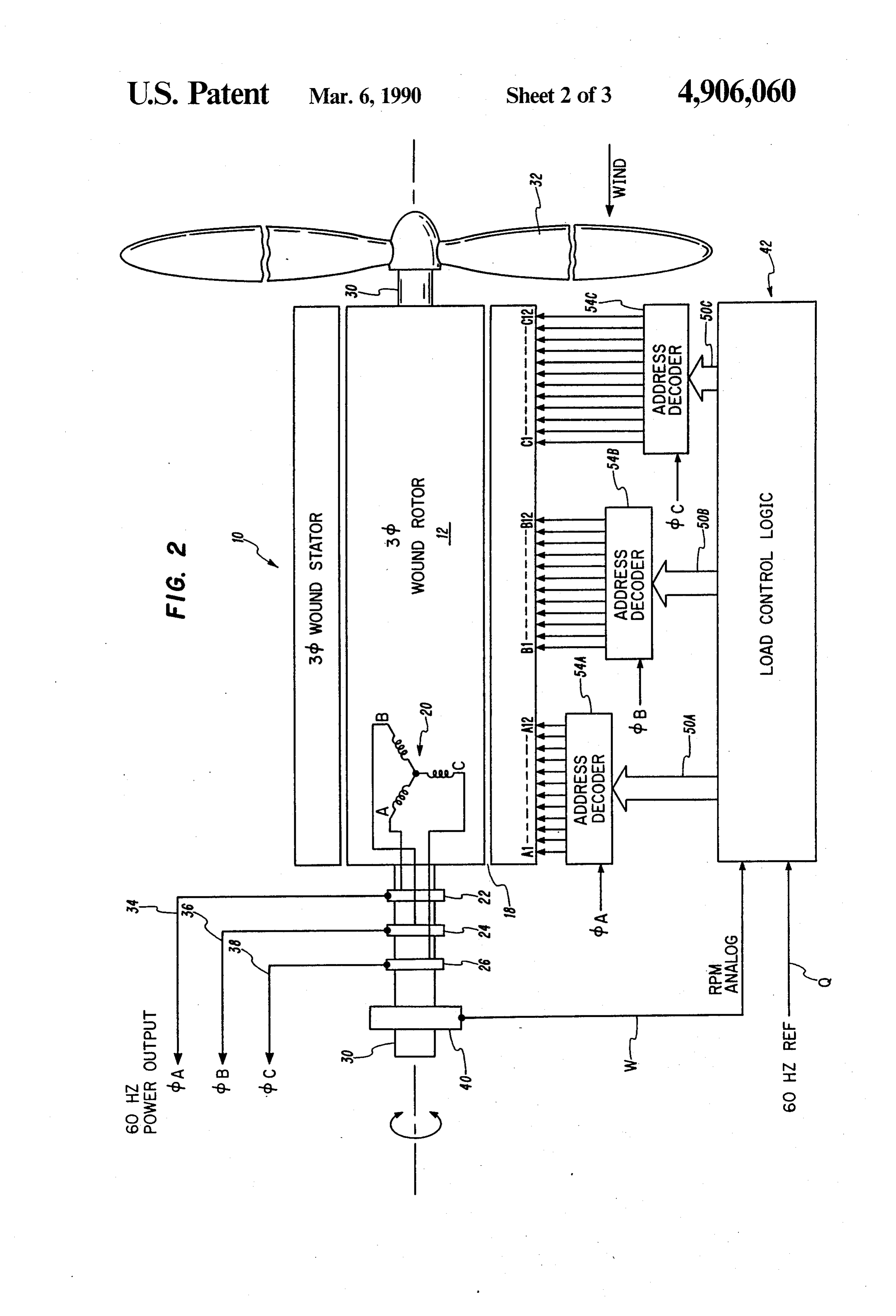
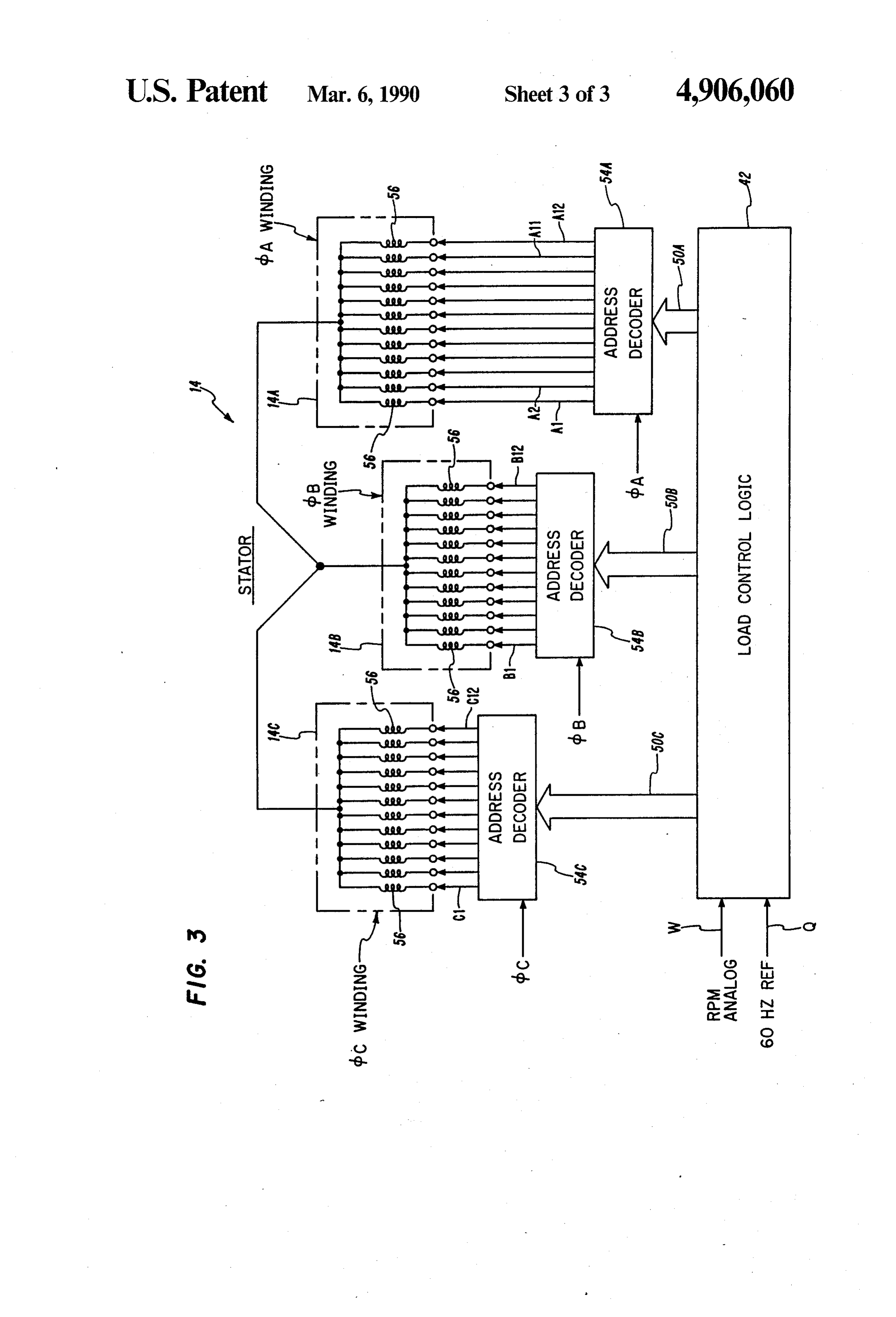
to the third electrical signal for enabling selected ones of the stator windings to increase the strength of the FIG. 1 is a schematic illustrating a first embodiment stator magnetic field and is responsive to the fourth of an apparatus for controlling the rotor speed in a electrical signal for disabling selected ones of the stator wind-driven alternator (shown in cross-section along windings to decrease the strength of the stator magnetic 60 the rotor axis), according to the present invention; field. FIG. 2 is a schematic illustrating a second embodi In another embodiment the stator includes a plurality ment of an apparatus for controlling the rotor sped in a of electrical inductor coils is each phase of the poly wind-driven alternator (shown in cross-section along phase stator winding. The control means is responsive the rotor axis), according to the present invention; and, to the third electrical signal for enabling selected ones 65 FIG. 3 is an electrical circuit diagram illustrating the of the coils in each phase of the stator winding to in excitation of selected coil groups within the stator crease the strength of the stator magnetic field and is winding, according to the second embodiment of the responsive to the fourth electrical signal for disabling present invention, as shown in FIG. 2.
Page 7
Referring to FIG. 1, rotor speed. is controlled by
DETAILED DESCRIPTION
PREFERRED EMBODIMENT
OF THE selectively energizing and de-energizing one or more stator units S1-S8. A tachometer 40 is attached to rotor
In the description which follows, like parts are shaft 28 for measuring the speed of rotation thereof. marked throughout the specification and drawings, 5 Tachometer 40 sends an analog signal W proportional respectively. The drawings are not necessarily to scale to rotor speed to a load control logic circuit 42. A stable and in some instances proportions have been exagger analog reference signal Q corresponding to the desired ated in order to more clearly depict certain features of rotor speed (1,800 RPM) to produce a 60 Hz output the invention. signal is also input to the logic circuit 42. Logic circuit Referring to FIG. 1, a wind-driven electrical alterna 10 42 includes a differential amplifier 44 for producing an tor is comprised of an annular stator 10 and a rotor 12, output signal E proportional to the difference of the which is concentrically disposed within stator 10. Rotor RPM signal W and the reference signal Q. 12 is journally supported for rotation with respect to If the amplitude of the RPM signal W exceeds the stator 10. Stator 10 has a plurality of discrete three 15 amplitude of the reference signal Q, the actual rotor phase windings 14 disposed thereon. Each winding 14 is speed is greater than the desired speed. The differential disposed within a discrete annular segment S1-S8 on (--E), amplifier 44 will then generate a positive analog signal stator 10. Although eight windings are illustrated in difference the amplitude of which is proportional to the FIG. 1, one skilled in the art will appreciate that the other hand,between the two input signals. If, on the actual number of windings is a matter of design choice. 20 than the reference signal Q,ofthetheactual the amplitude RPM signal W is less
Each stator winding 14 has three separate winding than the desired speed. The differentialrotor speed is less amplifier 44 will phases, as indicated by phase coil groups A, B and C.
The phase coil groups A, B and C are energized from a then generate a negative analog signal (-E), the ampli tude of which is proportional to the difference between conventional 60 Hz three-phase alternating current the two input signals.
supply 16 having three balanced output phases, bA, cbb 25 The output E of the differential amplifier 44 is input and dbC, which are displaced in time by 120 degrees. to an analog-to-digital converter 46 within logic circuit The flow of three-phase alternating current through 42, which converts the differential analog signal E to a one or more of the stator windings S1-S8 produces an digital data signal Z. A digital processor 48 is provided alternating magnetic field in airgap 18 between stator 10 for encoding the digital amplitude signals into respec and rotor 12. 30 tive binary coded digital data control words 50 in ac Rotor 12 has a symmetrical three-phase winding 20 disposed thereon, with separate phase windings A, B cordance with a control program stored in a memory unit 52 in the digital processor. The control signals and C. Each phase winding A, B and Cof rotor winding correspond with unique combinations of stator units 20 is respectively connected to a slip ring 22, 24 and 26 S1-S8, the windings 14 of which are to be energized or on rotor shaft 28. One end of rotor 12 is coupled to a 35 de-energized, as the case may be. propeller shaft 30, on which a propeller 32 is mounted. By energizing additional stator units, the stator mag Propeller 32 will spin around the axis of propeller shaft netic field is increased to increase the braking force on 30 in response to a force exerted on the propellerblades rotor 12, thereby reducing rotor speed when the actual by the wind, to impart rotational motion to rotor 12. As rotor speed is greater than the desired speed. When rotor 12 rotates within stator 10, the electrically con fewer stator units are energized, the stator magnetic ductive rotor winding 20 will cut through the magnetic field is reduced, which reduces the braking force on lines of flux established by stator windings 14 within airgap 18 to produce a three-phase alternating current rotor 14 and allows rotor 12 to spin faster when the actual rotor speed is less than the desired speed. If the in rotor winding 20. The magnitude of the current pro actual rotor speed is substantially equal to the desired duced in rotor winding 20 will of course be dependent 45 rotor speed, the differential amplifier 44 output E will upon the strength of the stator magnetic field and the be zero and a binary coded control signal 50 representa speed of rotation of rotor 12. The alternating electrical tive of a nominal combination of stator units S1-S8 will current generated in rotor winding 20 is transferred be generated.
through rings 22, 24 and 26 to respective output con The binary coded control signals are conducted, as ductors 34, 36 and 38, which are in turn connected to a 50 indicated at 50, to an address decoder/driver circuit 54 power distribution panel or power grid. wherein the binary coded control signals are decoded. In accordance with the present invention, the rota The driver circuitry 54 includes groups of three power tional speed of rotor 12 is maintained substantially con switches per stator unit (preferably power transistors or stant, despite variations in wind speed, to maintain a thyristors), each of which is connected to one of the constant frequency output signal, such as 60 Hz AC. 55 phase conductors A, B and C of each particular stator The output frequency of the alternator is directly pro winding 14, through power conductors A1, B1, C1, . . . portional to the rotational speed of rotor 12. In a three , A8, B8, C8, respectively. After the control signals are phase alternator, rotor 12 spins at a speed of approxi decoded, an address signal is generated to turn on or mately 1,800 revolutions per minute (RPM) to produce turn off selected ones of power switches which are a 60 Hz AC signal. The magnetic field created by the 60 electrically coupled to the particular stator windings 14 excitation of stator windings 14 acts as a brake to op which are to be energized or de-energized, as the case pose the rotation of rotor 12. The greater the strength of may be.
the stator magnetic field, the greater will be the braking For example, if all the stator windings 14 are ener effect on rotor 12. By varying the strength of the stator gized and the rotor speed falls below a threshold speed, magnetic field to compensate for changes in wind 65 logic circuit 42 will generate a control signal 50 which speed, a substantially constant rotor speed can be main instructs address decoder/driver circuit 54 to de-ener tained to achieve the desired output frequency, even gize stator windings 14 located in annular stator seg under relatively low wind speed conditions. ments S1 and S8. The decoder circuitry will respond by
Page 8
turning off the power switches attached to phase con winding 14 are selectively energized and de-energized. ductors (A1, B1, C1) and (A8, B8, C8), thereby de-ener Otherwise, the system and method for controlling the gizing the two stator windings 14 located in stator units speed of rotor 12 is essentially the same as described S1 and S8. When the corresponding power switches are above with reference to FIG. 1. turned off, the electrical circuit between the corre The system and method for controlling rotor speed in sponding phase conductors and excitation signal 16 will a three phase alternator according to the present inven be opened, thereby de-energizing the corresponding tion provides a relatively simple and economical system windings 14. The strength of the stator magnetic field for maintaining a substantially constant frequency out will be reduced, thereby permitting the rotor speed to put. Electrical power is conserved by eliminating the increase. 10 need for dump resistors and the like, which drain off If, for example, only two stator windings 14 in seg excess power in many types of conventional alternators. ments in S4 and S5 are energized and the actual rotor In accordance with the present invention the output speed exceeds the desired speed, logic circuit 42 will current of the alternator varies in response to variations generate a control signal 50 representing one or more in the stator magnetic field in order to maintain a con additional stator windings 14 which are to be energized. 15 stant output frequency despite variations in the wind or If it is desired to energize the stator windings 14 in other source of mechanical energy.
segments S3 and S6, decoder circuit 54 will send an Various embodiments of the invention have now address signal to the power switches coupled to the been described in detail. Since changes in and modifica corresponding phase conductors of the two windings 14 tions to the above-described preferred embodiment may in segments S3 and S6, thereby closing the correspond 20 be made without departing from the nature, spirit and ing switches and allowing excitation signal 16 to be scope of the invention, the invention is not to be limited applied to two stator windings 14 in stator units S3 and to said details except as set forth in the appended claims. S6 in addition to stator units S4 and S5 to increase the What is claimed is:
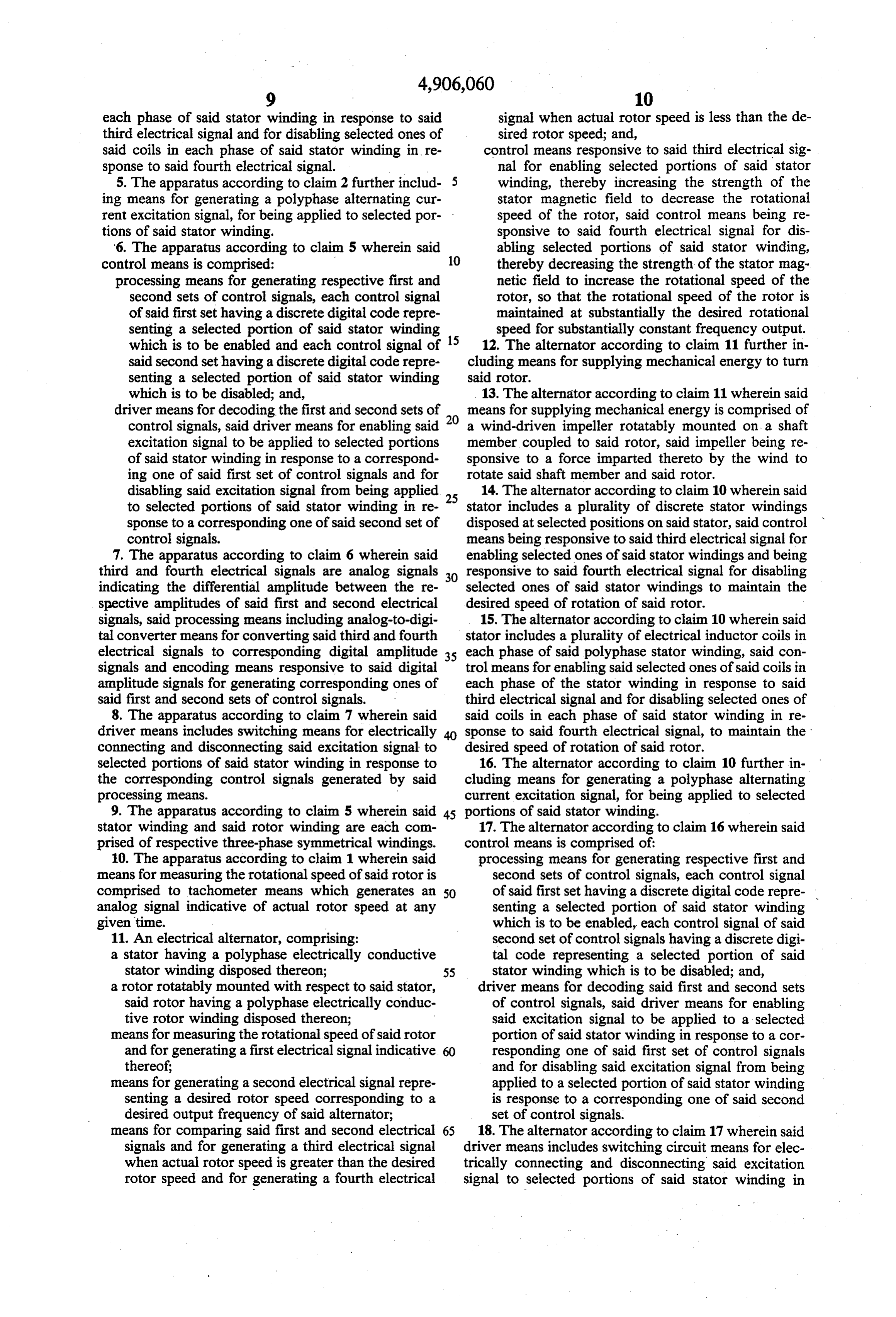
strength of the stator magnetic field and slow the rota 1. An apparatus for controlling the output frequency tional speed of rotor 12. 25 of an electrical alternator, said alternator having a stator One skilled in the art will appreciate that any one or and a rotor rotatably mounted with respect to stator, more of the eight separate stator windings 14 can be said stator and said rotor having respective polyphase energized or de-energized in combination at any given electrically conductive windings disposed thereon, said time to maintain a substantially constant rotor speed. apparatus comprising:
The wind speed may become excessive such that the 30 means for measuring the rotational speed of said rotor actual rotor speed exceeds the desired rotor speed, de and for generating a first electrical signal indicative spite the fact that all the stator windings 14 are ener thereof;
gized. In this event, rotor speed is limited by a mechani means for generating a second electrical signal repre cal governor (not shown) interposed between propeller senting a desired rotor speed corresponding to a 32 and rotor 12 to limit the speed of rotor 12 during high 35 desired output frequency of said alternator; wind conditions. Such control devices are known in the means for comparing said first and second electrical art and typically include means for aerodynamically signals and for generating a third electrical signal braking the rotor. One method of aerodynamically when actual rotor speed is greater than the desired braking the rotor is by varying the pitch of the propeller rotor speed and for generating a fourth electrical in the conventional manner. signal when actual rotor speed is less than the de Referring to FIGS. 2 and 3, an alternate embodiment sired rotor speed; and, of the invention is depicted. In this alternate embodi control means responsive to said third electrical sig ment stator 10 has a distributed three-phase winding 14. nal for enabling selected portions of said stator instead of separate winding groups S1-S8 as in the em winding, thereby increasing the strength of the bodiment shown in FIG. 1. Each stator phase winding 45 stator magnetic field to decrease the rotational 14A, 14B and 14C is comprised of a plurality of electri speed of the rotor, said control means being re cal inductor coils 56, each of which is electrically cou sponsive to said fourth electrical signal for dis pled through conductors A1-A12, B1-B12 and C1-C12 abling selected portions of said stator winding, to a particular power switch within driver circuitry thereby decreasing the strength of the stator mag 54A, 54B, 54C, respectively. In this configuration, one 50 netic field to increase the rotational speed of the or more individual coils within each phase of stator rotor.
winding 14 are selectively energized and de-energized 2. The apparatus according to claim 1 wherein said to increase or decrease the strength of the stator mag stator winding is comprised of a plurality of discrete netic field to maintain constant rotor speed. The binary stator windings disposed at predetermined positions on coded control signals 50A, 50B, 50C produced by load 55 said stator, said control means being responsive to said control logic circuit 42 correspond with unique combi third electrical signal for enabling selected ones of said nations of one or more coils 48 within each phase of stator windings and being responsive to said fourth stator winding 14 which are to be energized or de-ener electrical signal for disabling selected ones of said stator gized as determined by load control logic circuit 42. windings and being responsive to said fourth electrical For purposes of example only, the number of coils 56 60 signal for disabling selected ones of said stator wind in each phase winding is shown to be twelve. One 1ngs.
skilled in the art will appreciate that the number of coils 3. The apparatus according to claim 2 wherein said in each phase winding may be a number other than plurality of said stator windings are disposed on discrete twelve. Instead of selectively energizing and de-ener annular segments of said stator.
gizing all of the coils in selected ones of a plurality of 65 4. The apparatus according to claim 1 wherein said separate stator winding 14 (as in the embodiment shown stator includes a plurality of electrical inductor coils in in FIG. 1), one or more individual coils 56 within each each phase of said polyphase stator winding, said con phase group (bA, dB, bc) of a three-phase symmetrical trol means for enabling selected ones of said coils in
Page 9
each phase of said stator winding in response to said signal when actual rotor speed is less than the de third electrical signal and for disabling selected ones of sired rotor speed; and, said coils in each phase of said stator winding in re control means responsive to said third electrical sig sponse to said fourth electrical signal. nal for enabling selected portions of said stator 5. The apparatus according to claim 2 further includ- 5 winding, thereby increasing the strength of the ing means for generating a polyphase alternating cur stator magnetic field to decrease the rotational rent excitation signal, for being applied to selected por- - speed of the rotor, said control means being re tions of said stator winding. sponsive to said fourth electrical signal for dis 6. The apparatus according to claim 5 wherein said abling selected portions of said stator winding, control means is comprised: 10 thereby decreasing the strength of the stator mag processing means for generating respective first and netic field to increase the rotational speed of the second sets of control signals, each control signal rotor, so that the rotational speed of the rotor is of said first set having a discrete digital code repre maintained at substantially the desired rotational senting a selected portion of said stator winding speed for substantially constant frequency output. which is to be enabled and each control signal of 12. The alternator according to claim 11 further in said second set having a discrete digital code repre cluding means for supplying mechanical energy to turn senting a selected portion of said stator winding said rotor.
which is to be disabled; and, 13. The alternator according to claim 11 wherein said driver means for decoding the first and second sets of means for supplying mechanical energy is comprised of control signals, said driver means for enabling said 20 a wind-driven impeller rotatably mounted on a shaft excitation signal to be applied to selected portions member coupled to said rotor, said impeller being re of said stator winding in response to a correspond sponsive to a force imparted thereto by the wind to ing one of said first set of control signals and for rotate said shaft member and said rotor. disabling said excitation signal from being applied 25 14. The alternator according to claim 10 wherein said to selected portions of said stator winding in re stator includes a plurality of discrete stator windings sponse to a corresponding one of said second set of disposed at selected positions on said stator, said control control signals. means being responsive to said third electrical signal for 7. The apparatus according to claim 6 wherein said enabling selected ones of said stator windings and being third and fourth electrical signals are analog signals 30 responsive to said fourth electrical signal for disabling indicating the differential amplitude between the re selected ones of said stator windings to maintain the spective amplitudes of said first and second electrical desired speed of rotation of said rotor. signals, said processing means including analog-to-digi 15. The alternator according to claim 10 wherein said tal converter means for converting said third and fourth stator includes a plurality of electrical inductor coils in electrical signals to corresponding digital amplitude 35 each phase of said polyphase stator winding, said con signals and encoding means responsive to said digital trol means for enabling said selected ones of said coils in amplitude signals for generating corresponding ones of each phase of the stator winding in response to said said first and second sets of control signals. third electrical signal and for disabling selected ones of 8. The apparatus according to claim 7 wherein said said coils in each phase of said stator winding in re driver means includes switching means for electrically 40 sponse to said fourth electrical signal, to maintain the connecting and disconnecting said excitation signal to desired speed of rotation of said rotor. selected portions of said stator winding in response to 16. The alternator according to claim 10 further in the corresponding control signals generated by said cluding means for generating a polyphase alternating processing means. current excitation signal, for being applied to selected 9. The apparatus according to claim 5 wherein said 45 portions of said stator winding.
stator winding and said rotor winding are each com 17. The alternator according to claim 16 wherein said prised of respective three-phase symmetrical windings. control means is comprised of:
10. The apparatus according to claim 1 wherein said processing means for generating respective first and means for measuring the rotational speed of said rotor is second sets of control signals, each control signal comprised to tachometer means which generates an 50 of said first set having a discrete digital code repre analog signal indicative of actual rotor speed at any senting a selected portion of said stator winding given time. which is to be enabled, each control signal of said 11. An electrical alternator, comprising: second set of control signals having a discrete digi a stator having a polyphase electrically conductive tal code representing a selected portion of said stator winding disposed thereon; 55 stator winding which is to be disabled; and, a rotor rotatably mounted with respect to said stator, driver means for decoding said first and second sets said rotor having a polyphase electrically conduc of control signals, said driver means for enabling tive rotor winding disposed thereon; said excitation signal to be applied to a selected means for measuring the rotational speed of said rotor portion of said stator winding in response to a cor and for generating a first electrical signal indicative 60 responding one of said first set of control signals thereof; and for disabling said excitation signal from being means for generating a second electrical signal repre applied to a selected portion of said stator winding senting a desired rotor speed corresponding to a is response to a corresponding one of said second desired output frequency of said alternator; set of control signals.
means for comparing said first and second electrical 65 18. The alternator according to claim 17 wherein said signals and for generating a third electrical signal driver means includes switching circuit means for elec when actual rotor speed is greater than the desired trically connecting and disconnecting said excitation rotor speed and for generating a fourth electrical signal to selected portions of said stator winding in
Page 10
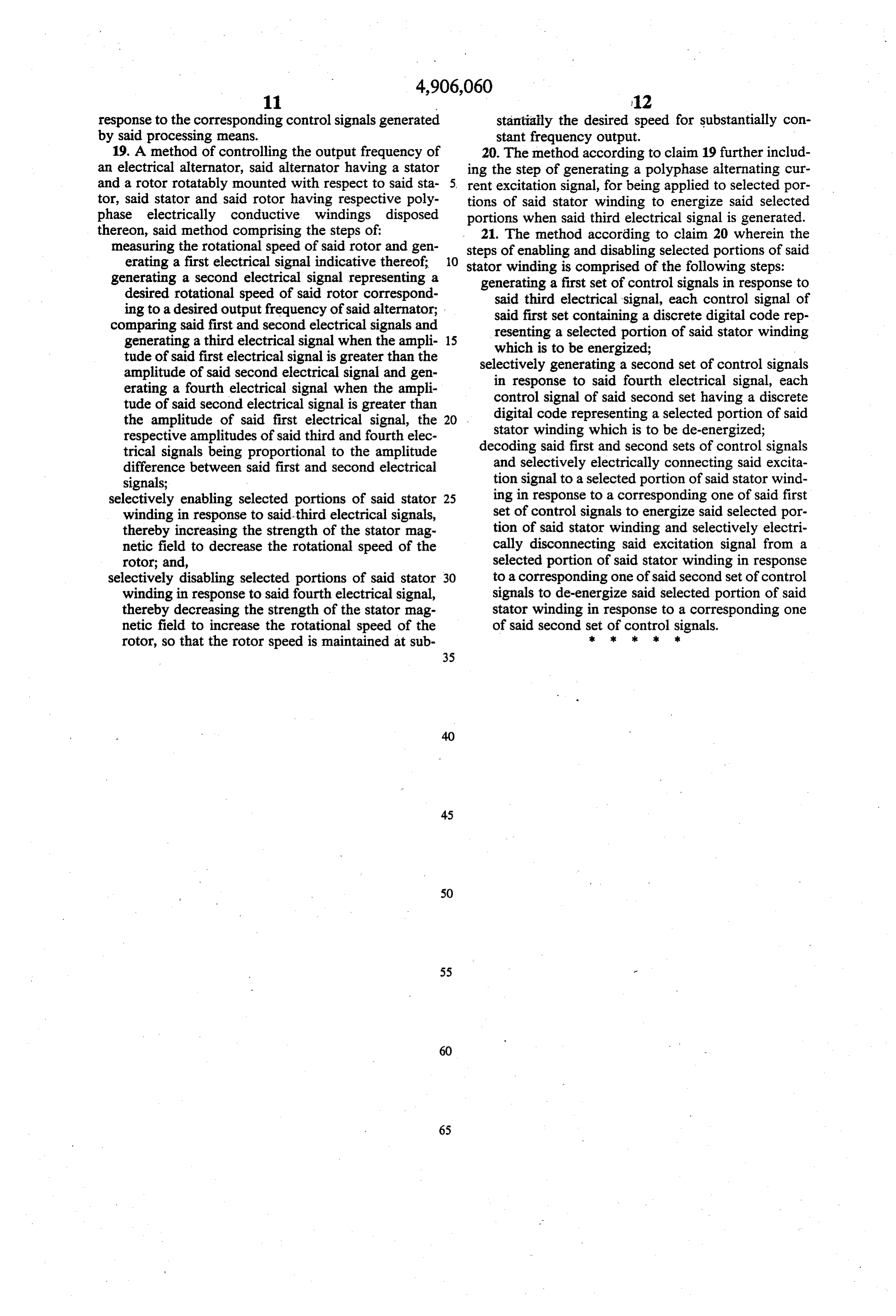
response to the corresponding control signals generated stantially the desired speed for substantially con by said processing means. stant frequency output.
19. A method of controlling the output frequency of 20. The method according to claim 19 further includ an electrical alternator, said alternator having a stator ing the step of generating a polyphase alternating cur and a rotor rotatably mounted with respect to said sta 5 rent excitation signal, for being applied to selected por tor, said stator and said rotor having respective poly tions of said stator winding to energize said selected phase electrically conductive windings disposed portions when said third electrical signal is generated. thereon, said method comprising the steps of 21. The method according to claim 20 wherein the measuring the rotational speed of said rotor and gen steps of enabling and disabling selected portions of said erating a first electrical signal indicative thereof; stator winding is comprised of the following steps: generating a second electrical signal representing a generating a first set of control signals in response to desired rotational speed of said rotor correspond said third electrical signal, each control signal of ing to a desired output frequency of said alternator; . said first set containing a discrete digital code rep comparing said first and second electrical signals and resenting a selected portion of said stator winding generating a third electrical signal when the ampli 15 which is to be energized;
tude of said first electrical signal is greater than the selectively generating a second set of control signals amplitude of said second electrical signal and gen in response to said fourth electrical signal, each erating a fourth electrical signal when the ampli control signal of said second set having a discrete tude of said second electrical signal is greater than digital code representing a selected portion of said the amplitude of said first electrical signal, the 20 stator winding which is to be de-energized; respective amplitudes of said third and fourth elec trical signals being proportional to the amplitude decoding said first and second sets of control signals difference between said first and second electrical and selectively electrically connecting said excita signals; tion signal to a selected portion of said stator wind selectively enabling selected portions of said stator 25 ing in response to a corresponding one of said first winding in response to said-third electrical signals, set of control signals to energize said selected por thereby increasing the strength of the stator mag tion of said stator winding and selectively electri netic field to decrease the rotational speed of the cally disconnecting said excitation signal from a rotor; and, selected portion of said stator winding in response selectively disabling selected portions of said stator 30 to a corresponding one of said second set of control winding in response to said fourth electrical signal, signals to de-energize said selected portion of said thereby decreasing the strength of the stator mag stator winding in response to a corresponding one netic field to increase the rotational speed of the of said second set of control signals. rotor, so that the rotor speed is maintained at sub k s s s
Page 11
UNITED STATES PATENT AND TRADEMARK OFFICE
CERTIFICATE OF CORRECTION
INVENTOR (S) : David L. Claude it is certified that error appears in the above-identified patent and that said Letters Patent is hereby corrected as shown below:
Column 4, line 62, "sped" should be -- speed --. Column 9, line 10, "comprised : " should be -- comprised
Signed and Sealed this
Eighth Day of January, 1991
Attest:
HARRY F. MANBECK, JR
Attesting Officer Commissioner of Patents and Trademarks
Provenance
- Collection
- Cited prior art
- Original PDF
- patentimages.storage.googleapis.com →
- Filed
- 1989-03-23
- Pages
- 11
- Method
- pdftotext (the PDF's own text layer) + pdftoppm 300dpi page scans
- Source
- Google Patents bibliographic record
- Granted
- 1990-03-06
- Inventors
- David L. Claude; Twind Energy Corp
- Transcribed from
- patentimages.storage.googleapis.com →