patent · US5782225
Vaporization system
21 July 1998
Page 1 — bibliographic record
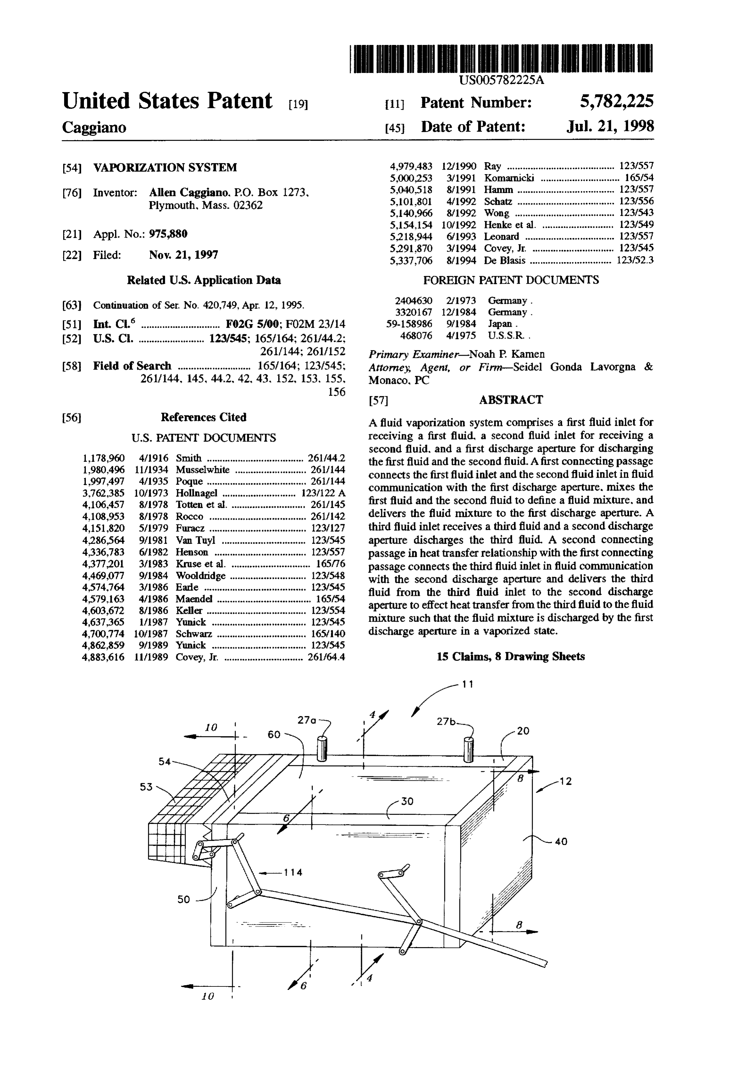
United States Patent (19) 11 Patent Number: 5,782,225 Caggiano 45 Date of Patent: Jul. 21, 1998 54 WAPORIZATION SYSTEM 4,979.483 12/1990 Ray ......................................... 123/557 5,000253 3/1991 Komarnicki . ... 165/54 76 Inventor: Allen Caggiano, P.O. Box 1273, 5,040,518 8/1991 Hamm ...... 123/557 Plymouth, Mass. 02362 5,101,801 4/1992 Schatz .. 123,556 5,140,966 8/1992 Wong ...................................... 123/543 5,154,154 10/1992 Henke et al. ........................... 123/549 21 Appl. No.: 975,880 5,218,944 6/1993 Leonard .................................. 123/557 5,291,870 3/1994 Covey, Jr. ... 123/545 22 Filed: Nov. 21, 1997 5,337,706 8/1994 De Blasis ............................... 123/523 Related U.S. Application Data FOREIGN PATENT DOCUMENTS (63. Continuation of Ser. No. 420,749, Apr. 12, 1995. 2404630 2/1973 Germany.
51 Int. Cl. ........................ F02G 5700; F02M 23/14 59-158986 971984 Japan.
52 U.S. C. ......................... 123/545; 165/164; 261/44.2: 468.076 4/1975 U.S.S.R. 261/144; 261/152 Primary Examiner-Noah P. Kamen 58 Field of Search ............................ 165/164; 1231545: Attorney; Agent, or Firm-Seidel Gonda Lavorgna & 261/144, 145, 44.2, 42, 43, 152, 153, 155, Monaco, PC
56) References Cited A fluid vaporization system comprises a first fluid inlet for
second fluid, and a first discharge aperture for discharging 1,178,960 4/1916 Smith ..................................... 261f44.2 the first fluid and the second fluid. A first connecting passage 1980,496 11/1934 Musselwhite ...... 261/144 connects the first fluid inlet and the second fluid inlet in fluid 1997,497 4/1935 Poque ...................................... 26/144 communication with the first discharge aperture, mixes the 3.762,385 10/1973 Hollnagel .... ... 23/122A first fluid and the second fluid to define a fluid mixture, and 4,106,457 8/1978 Totten et al. ..., 26/145 4,108,953 8/1978 Rocco . ... 261/142 delivers the fluid mixture to the first discharge aperture. A 4,151,820 5/1979 Furacz ..... ... 23/27 third fluid inlet receives a third fluid and a second discharge 4286,564 9/1981 Van Tuyl ... 123/545 aperture discharges the third fluid. A second connecting 4,336,783 6/1982 Henson ....... ... 123,557 passage in heat transfer relationship with the first connecting 4,377,201 3/1983 Kruse et al. ... 165/76 passage connects the third fluid inlet in fluid communication 4,469,077 9/1984 Wooldridge ... ... 123/548 with the second discharge aperture and delivers the third 4,574.764 3/1986 Earde ....... ... 123/545 fluid from the third fluid inlet to the second discharge 4.579,163 4/1986 Maendel. ... 165/54 4,603,672 8/1986 Keller ...... ... 123/554 aperture to effect heat transfer from the third fluid to the fluid 4,637.365 1/1987 Yunick ... . 123/545 mixture such that the fluid mixture is discharged by the first 4,700,774 10/1987 Schwarz. . . 165/140 discharge aperture in a vaporized state. 4,862,859 9/1989 Yunick .................................... 123/545 4,883,616 11/1989 Covey, Jr. .............................. 261/64.4 15 Claims, 8 Drawing Sheets
Page 2
Drawing sheet — no readable text.
Page 3
Drawing sheet — no readable text.
Page 4
Drawing sheet — no readable text.
Page 5
Drawing sheet — no readable text.
Page 6
Drawing sheet — no readable text.
Page 7
Drawing sheet — no readable text.
Page 8
Drawing sheet — no readable text.
Page 9
Drawing sheet — no readable text.
Page 10
WAPORIZATION SYSTEM flow of a fuel/air mixture within the system and allow for expansion of the heated fuel/air mixture therein.
This is a continuation of co-pending application Ser. No. It is a further object of the present invention to provide a 08/420,749 filed on Apr. 12, 1995. fluid vaporization system which can be utilized in both BACKGROUND OF THE INVENTION carbureted and fuel injected engines.
It is yet a further object of the present invention to provide 1. Field of the Invention a fluid vaporization system with numerous safety features The invention relates generally to a fluid vaporization that eliminate the risks of predetonation and excessive fuel system and, more particularly, to a fluid vaporization system vapor accumulation.
which heats a mixture of fluids and delivers the mixture in 10 The foregoing and other objects of the present invention a vaporized state. The fluid vaporization system is particu are carried out by a fluid vaporization system including a larly well adapted for heating a mixture of air and liquid fuel first fluid inlet for receiving a first fluid, a second fluid inlet and delivering it to an internal combustion engine as a vapor. for receiving a second fluid, and a first discharge aperture for 2. Background of the Invention 15 discharging the first and second fluids. A first connecting
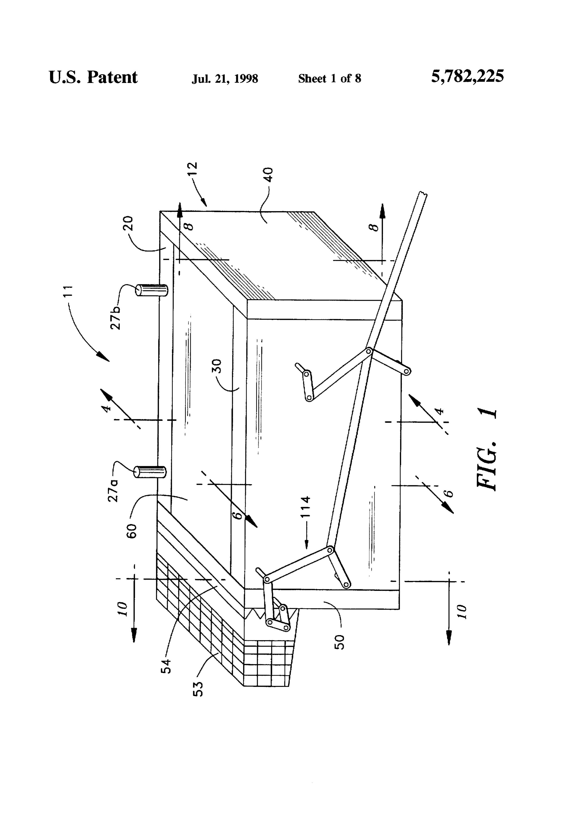
In an effort to reduce pollution and conserve resources, passage connects the first fluid inlet and the second fluid continual efforts are being made to improve the performance inlet in fluid communication with the first discharge of internal combustion engines, particularly in automobiles aperture, mixes the first fluid and the second fluid to form a and other motor vehicles. Motor vehicle engines must oper fluid mixture, and delivers the fluid mixture to the first ate as efficiently as possible while simultaneously minimiz 20 discharge aperture. A third fluid inlet receives a third fluid ing emissions and providing sufficient power. Toward these and a second discharge aperture discharges the third fluid. A goals, it has been sought to provide the most efficient and second connecting passage in heat transferrelationship with complete combustion of the fuel/air mixture consumed by the first connecting passage connects the third fluid inlet in the engine. In order to improve combustion of the fuel/air fluid communication with the second discharge aperture and mixture, one approach has been to heat the fuel/air mixture 25 delivers the third fluid from the third fluid inlet to the second to a vapor state before the fuel enters the engine. However, discharge aperture to effect heat transfer from the third fluid this and other attempts to achieve improved engine perfor to the fluid mixture such that the fluid mixture is discharged mance and reduced emissions by vaporizing the fuel/air by the first discharge aperture in a vaporized state. mixture have suffered from a number of shortcomings. BRIEF DESCRIPTION OF THE DRAWINGS Some attempts have suffered from an inability to suffi 30 ciently control the amount of vaporized fuel produced under The foregoing summary, as well as the following detailed all engine load conditions, especially under full load con description of the preferred embodiment of the invention, ditions. Other attempts have suffered from premature deto will be better understood when read in conjunction with the nation of the vaporized fuel prior to reaching the engine and appended drawings. For the purpose of illustrating the excessive accumulation of vaporized fuel outside of the 35 invention, there is shown in the drawings an embodiment engine causing safety concerns. Yet other attempts have which is presently preferred. It should be understood, suffered from the inability to produce sufficient vaporized however, that the invention is not limited to the precise fuel under engine loads greater than an idle condition. arrangements and instrumentalities shown. In the drawings: Accordingly, an improved fluid vaporization system is FIG. 1 is a perspective view of a vaporizing unit desired that provides a more optimal and effective fuel/air employed in a fluid vaporization system according to an mixture to an engine and is capable of supplying a fuel/air embodiment of the present invention;
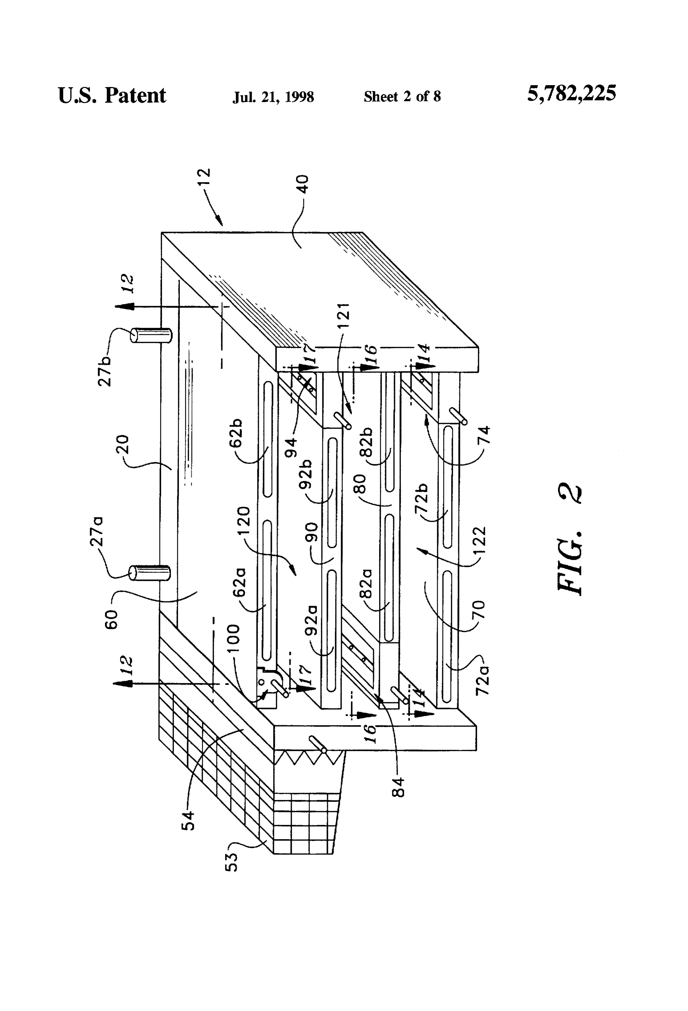
mixture in a vaporized state such that fuel efficiency is FIG. 2 is a perspective view of the vaporizing unit of FIG. increased while emissions and safety concerns are 1 with the front outer plate assembly removed;
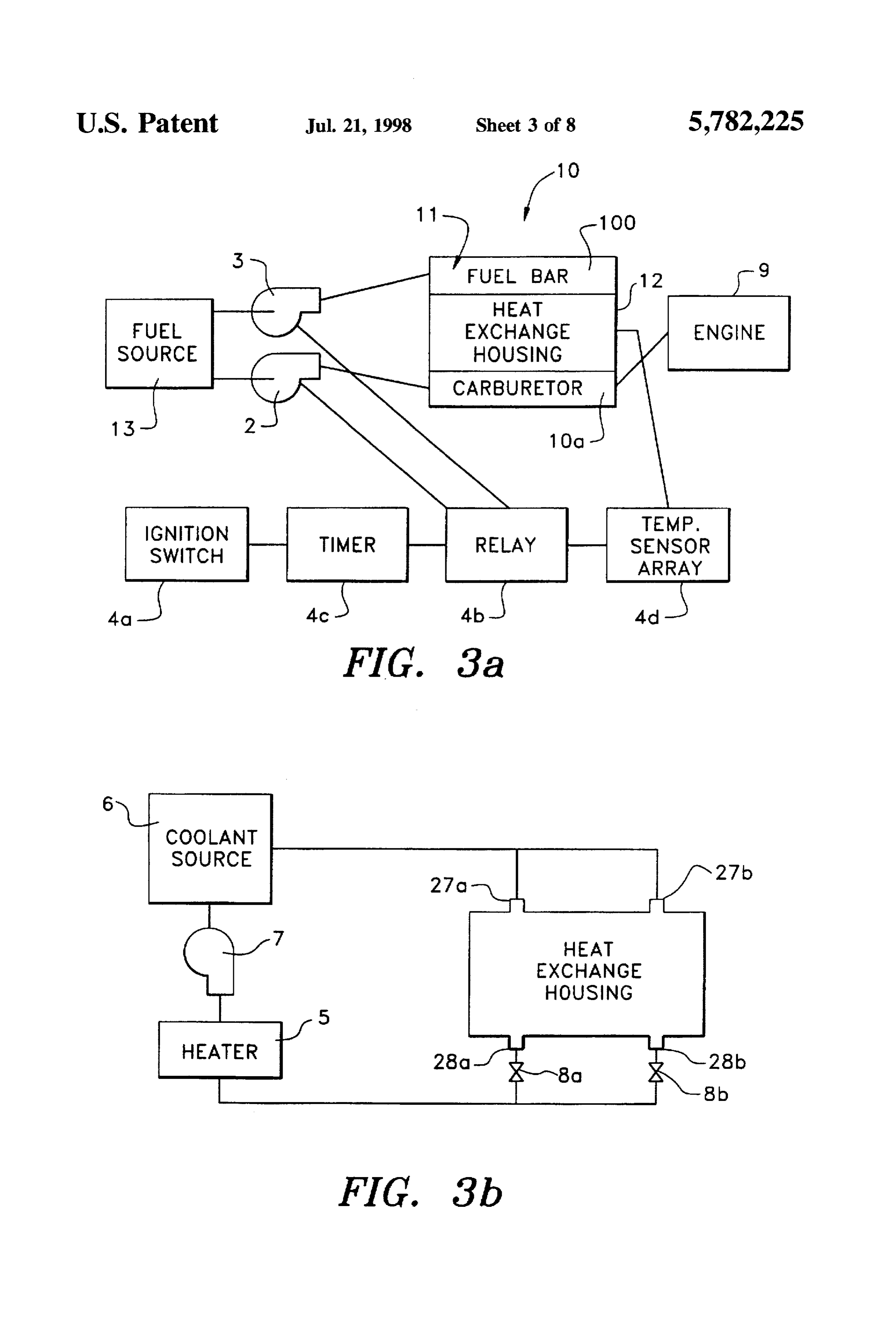
decreased. FIG. 3a is a block diagram showing the fuel circuit of the SUMMARY OF THE INVENTION 45 vaporizing system according to the present invention; It is an object of the present invention to provide a highly circuit of thea block
FIG. 3b is fluid diagram showing the hydraulic coolant vaporization system according to the efficient fluid vaporization system which employs a dual present invention;
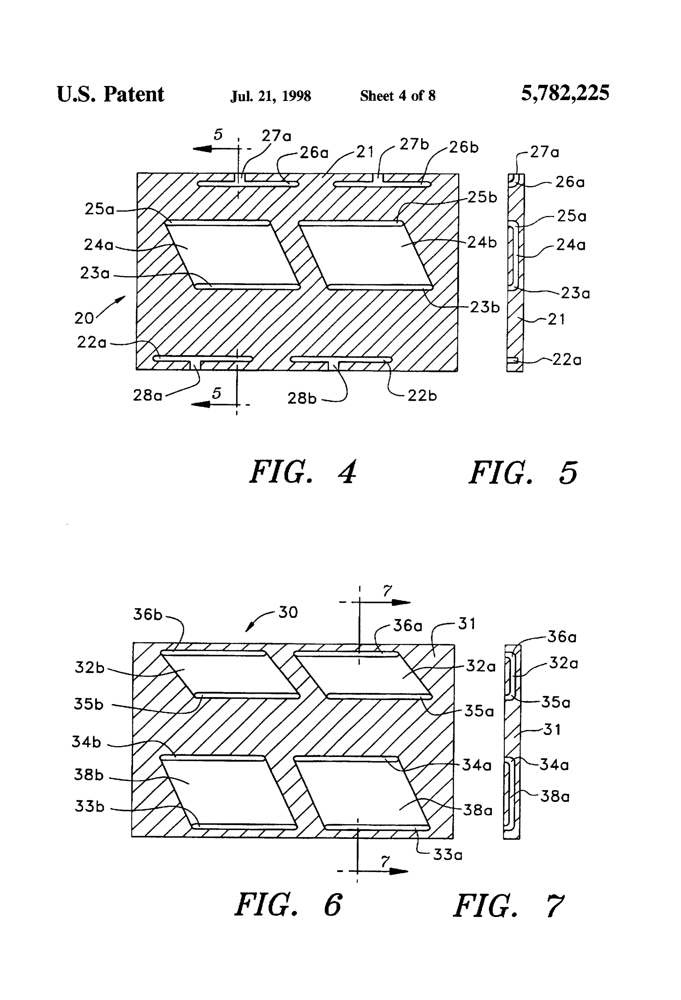
cross-counterflow heat exchanger to provide a fuel/air vapor FIG. 4 is a cross sectional view of the back outer plate mixture to an internal combustion engine to increase the fuel 50 assembly, taken along line IV-TV of FIG. 1; efficiency and decrease emissions.
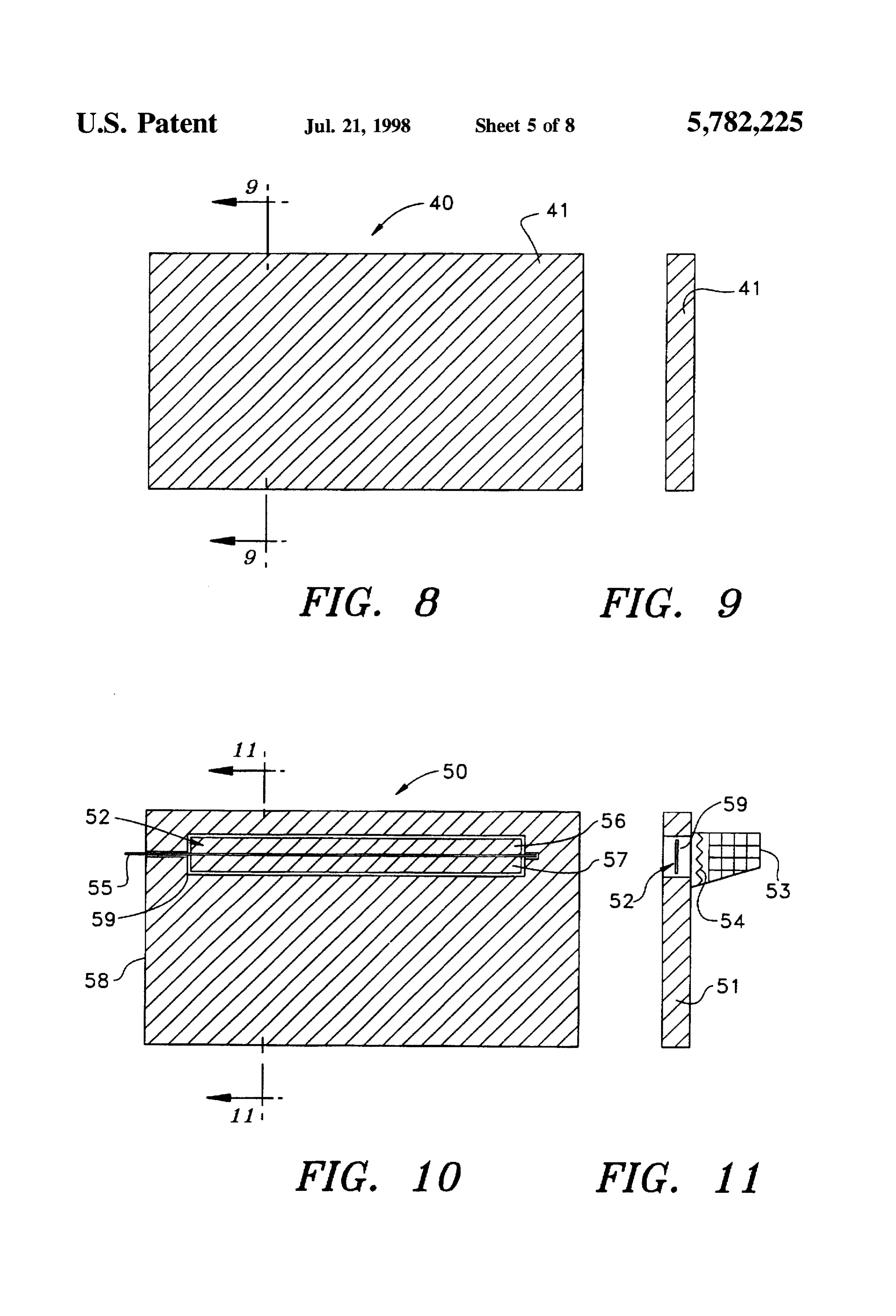
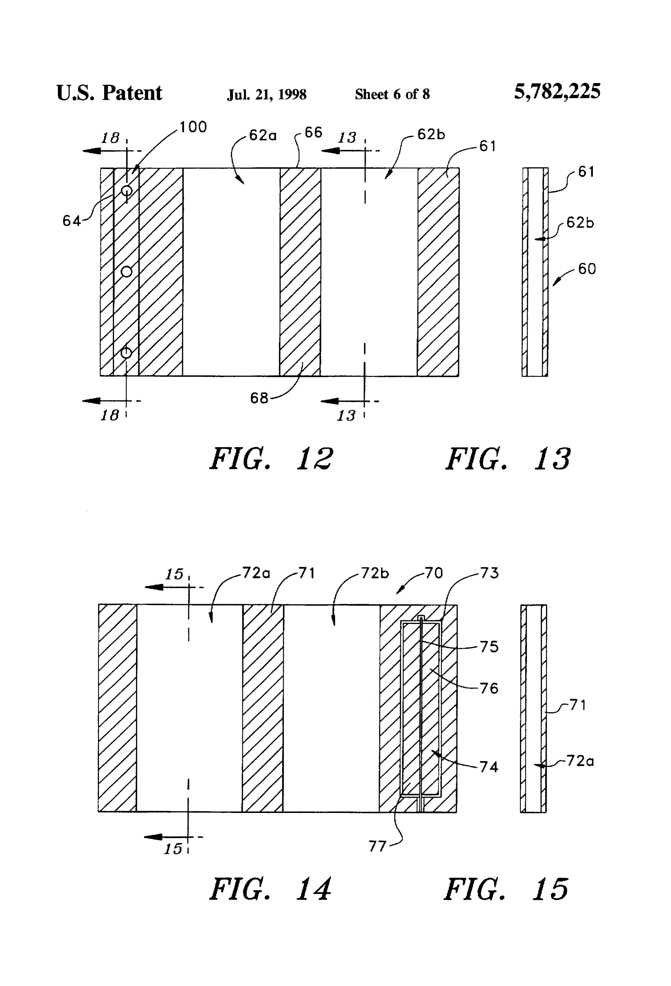
It is another object of the present invention to provide a FIG. 5 is a cross sectional view of the back outer plate fluid vaporization system for an internal combustion engine assembly, taken along line V-V of FIG. 4; in which airflow, fuel flow, and coolant or exhaust gas flow assembly,FIG. 6 is a cross sectional view of the front outer plate are all independently controllable such that a fuel/air mix 55 taken along line VI-VI of FIG. 1; ture flowing through the system is fully vaporized under all FIG. 7 is a cross sectional view of the front outer plate engine load conditions. assembly, taken along line VII-VII of FIG. 6; It is yet another object of the present invention to provide FIG. 8 is a cross sectional view of the right side outer plate a fluid vaporization system comprising a vaporizing unit assembly, taken along line VIII-VIII of FIG. 1; which is easily fabricated, assembled and disassembled to FIG.9 is a cross sectional view of the right side outer plate reduce manufacturing costs and facilitate field repairs. assembly, taken along line DX-DX of FIG. 8: It is a further object of the invention to provide a fluid FIG. 10 is a cross sectional view of the left side outer plate vaporization system which can precisely control the amount assembly, taken along line X-X of FIG. 1; of fuel/air mixture introduced into the vaporizing unit to FIG. 11 is a cross sectional view of the left side outer plate adequately power an engine under any load condition. 65 assembly, taken along line XI-XI of FIG. 10; It is a further object of the present invention to provide a FIG. 12 is a cross sectional view of the upper outer plate fluid vaporization system which can precisely control the assembly, taken along line XII-XII of FIG. 2;
Page 11
FIG. 13 is a cross sectional view of the upper outer plate assemblies 60 and 70 comprise upper and lower plates 61 assembly, taken along line XII-XIII of FIG. 12; and 71, respectively, and the plate assemblies 20.30, 40 and FIG. 14 is a cross sectional view of the lower outer plate 50 comprise side plates 21, 31, 41 and 51. respectively, assembly, taken along line XIV-XIV of FIG. 2; connecting the upper plate 61 and the lower plate 71 in spaced relation so as to define an airtight sealed chamber.
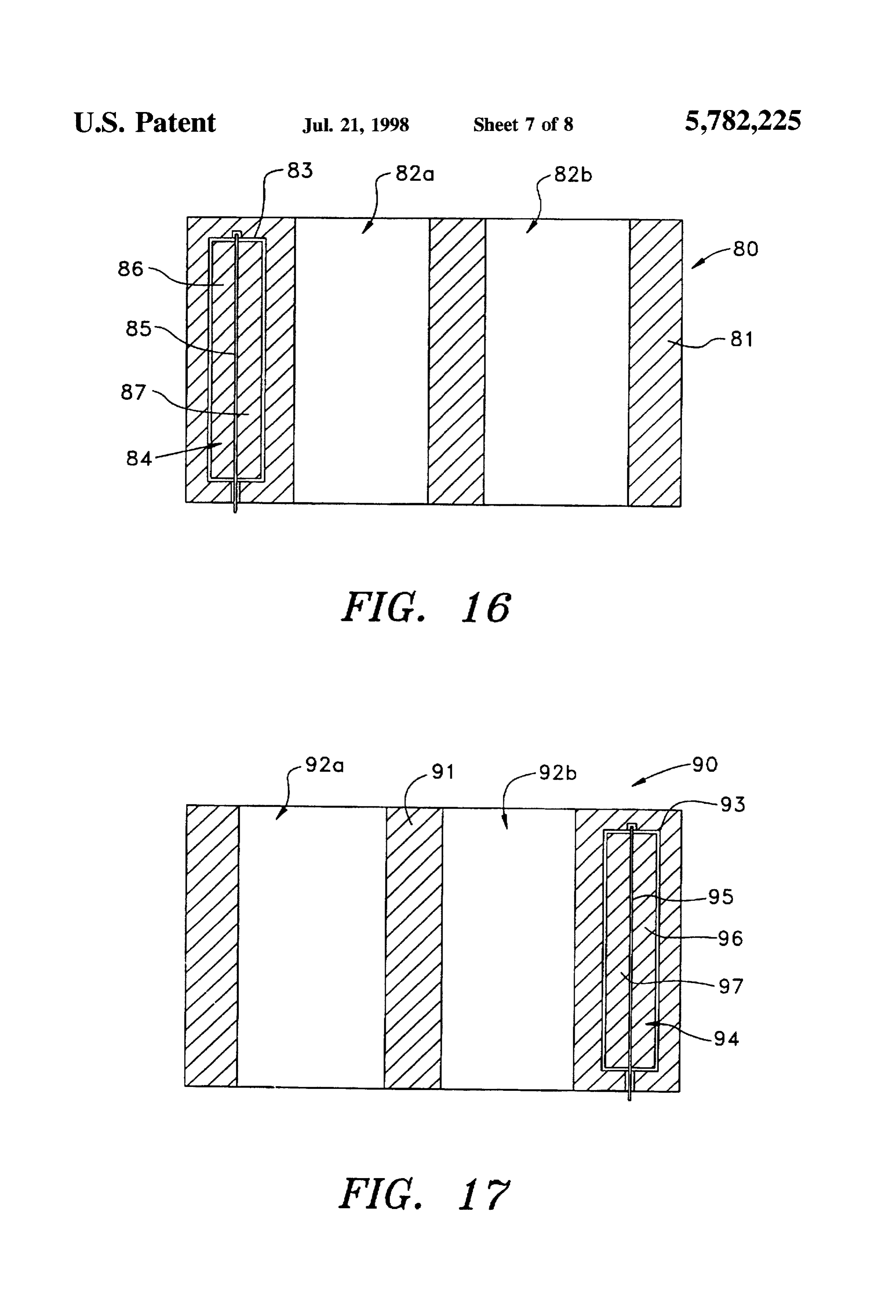
FIG. 15 is a cross sectional view of the lower outer plate The plate assemblies 80 and 90 comprise intermediate plates assembly, taken along line XV-XV of FIG. 14; 81 and 91 disposed within the sealed chamber and connected FIG. 16 is a cross sectional view of the lower inner plate to the side plates 40 and 50. As shown in FIG. 1, the assembly. taken along line XVI-XVI of FIG. 2; vaporizing unit 11 is linked to a conventional progressive FIG. 17 is a cross sectional view of the upper inner plate linkage 114 which controls the operation of the fuel bar assembly 100 as further described below.
assembly, taken along line XVI-XVII of FIG. 2;
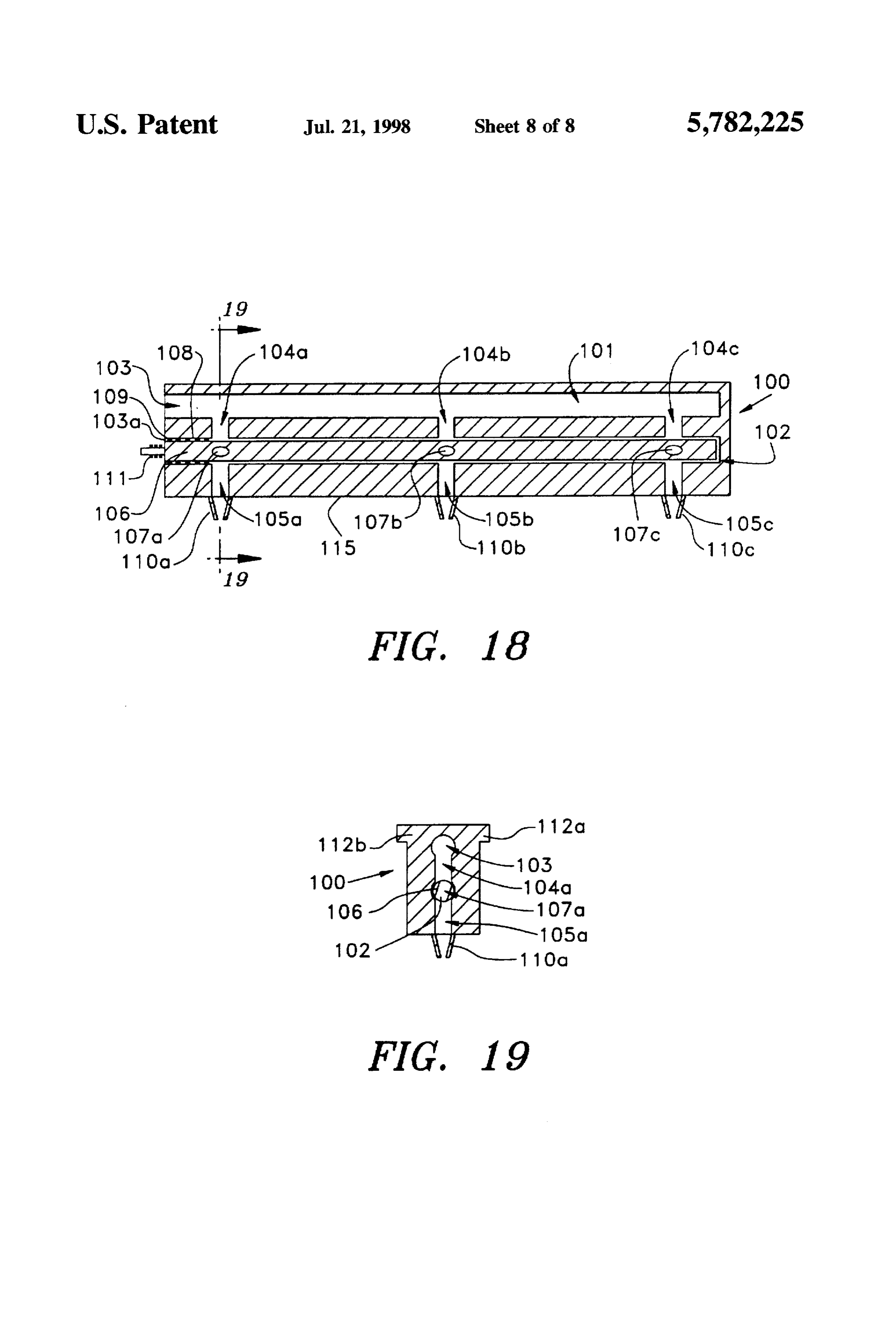
FIG. 18 is a cross sectional view of the fuel bar assembly, outer As best shown in FIGS. 4 and 5, the side plate or rear taken along line XVIII-XVIII of FIG. 12; and plate 21 of the rear outer plate assembly 20 includes a left inlet 28a, a right inlet 28b, a left discharge outlet 27a,
FIG. 19 is a cross sectional view of the fuel bar assembly. 15. and a right discharge outlet 27b. The left and right inlets 28a taken along line XIX-XIX of FIG. 18. and 28b open out from the bottom wall of the plate 21, and
DETALED DESCRIPTION OF THE
the left and right outlets 27a and 27b open out from the top wall of the plate 21. The left inlet 28a connects to a left
PREFERRED EMBODIMENT lower channel 22a, and the right inlet 28b connects to a right The preferred embodiment of the vaporizing system lower channel lower 22b. The left lower channel 22a and the right channel 22b have openings in the inner wall of the according to the present invention is described below with a plate specific application to an internal combustion engine, where upper21. The left discharge outlet 27a connects to the left the mixture of fluids is, for example, a mixture of air and nects to a right26a channel and the right discharge outlet 27b con upper channel 26b. Left upper channel 26a liquid fuel which is heated and delivered by the fluid and right upper channel 26b have openings in the inner wall vaporization system to the internal combustion engine in a 25 of plate 21. The plate 21 also includes a left medial cavity vaporized state. However, it will be understood by those of 24a and a right medial cavity 24b disposed at an interme ordinary skill in the art that the present invention is also diate portion of the plate 21. The left medial cavity 24a suitable for other applications requiring the input of fluids in connects with a left upper medial channel 25a and a left a vaporized state, such as, for example, heating oil fuel lower medial channel 23a. The right medial cavity 24b processors, air conditioning systems, refrigeration systems 30 connects with a right upper medial channel 25b and a right and ice storage tanks. It will further be understood that the lower medial channel 23b. Medial channels 23a, 23b, 25a fluids could be one or more types of liquids or a combination and 25b all open out from the inner wall of the plate 21. of one or more types of liquids and gases. As shown in FIGS. 6 and 7... the side plate or front outer Certain terminology is used in the following description plate 31 of the front outer plate assembly 30 includes a left for convenience only and is not intended to be limiting. The 35 lower cavity 38a, a left upper cavity 32a, a right lower cavity words right, left, rear, front, upper, lower, inner and outer 38b, and a right upper cavity 32b. The left lower cavity 38a designate directions in the drawing to which reference is connects with a left lower cavity lower channel 33a and a made. Such terminology includes the words above specifi left lower cavity upper channel 34a. The right lower cavity cally mentioned and words of similar import. 38b connects with a right lower cavity lower channel 33b Referring now to the drawings in detail, wherein like and a right lower cavity upper channel 34b. The left upper reference numerals are used to designate identical or corre cavity 32a connects with a left upper cavity lower channel sponding parts throughout the several views. FIGS. 3a and 35a and a left upper cavity upper channel 36a, The right 3b show a fluid vaporization system, generally designated upper cavity 32b connects with a right upper cavity lower 10, according to an embodiment of the present invention. channel 35b and a right upper cavity upper channel 36b. The fluid vaporization system 10 is applied in connection 45 Channels 33a, 33b, 34a, 34b, 35a, 35b, 36a, and 36b all with an internal combustion engine and comprises a vapor open out from the inner wall of the plate 31. izing unit 11 connected to the carburetor 10a of an engine 9. FIGS. 8 and 9 show cross sectional views of the right side In the present embodiment, the mixture of fluids comprises, plate assembly 40. In the present embodiment, the right side for example, a mixture of a liquid fuel, such as hydrocarbon plate assembly 40 is a solid side plate 41. fuel, and air. 50 Referring now to FIGS. 10 and 11, the left side outer plate As shown in FIGS. 1 and 2, the vaporizing unit 11 assembly 50 includes a left side plate 51 and an inlet channel comprises a heat exchange housing 12 and a fuel bar 59 extending therethrough. An air damper assembly 52 is assembly 100 for controlling the amount of fuel entering the rotatably disposed within the inlet channel 59 for controlling vaporizing unit 11 as further described below. The heat the volume of air that enters through inlet channel 59. The exchange housing 12 is preferably formed of plated, die cast, 55 damper assembly 52 includes a central rod 55 and radially or extruded aluminum, and is sufficiently sealed such that extending vanes 56 and 57. The central rod 55 extends past the air and fuel being mixed and vaporized within the a frontal edge 58 of the plate 51 for attachment to the housing do not escape therefrom. It is understood that the progressive linkage 114 shown in FIG. 1. Rotation of the fluid vaporization system of the present invention could be damper assembly 52 is controlled by the progressive linkage manufactured from other materials such as iron, copper. 114 to regulate the amount of air drawn through the heat stainless steel, or highly thermally conductive polymers exchange housing 12. Preferably, an air filter 53 is attached depending on the application. The heat exchange housing 12 to the inlet channel 59 for removing contaminants from the includes a rear outer plate assembly 20, a front outer plate incoming air. The air filter 53 can also contain an air heating assembly 30, a right side outer plate assembly 40, a left side coil 54 for raising the temperature of the air entering the air outer plate assembly 50, an upper outer plate assembly 60. 65 filter.
a lower outer plate assembly 70, a lower inner plate assem Referring now to FIGS. 12 and 13, the upper plate 61 of bly 80, and an upper inner plate assembly 90. The plate the upper outer plate assembly 60 is provided with a left side
Page 12
channel 62a, a right side channel 62b and fluid inlet or bore hydrocarbon fuel-burning internal combustion engine, it has 64. The left side channel 62a, the right side channel 62b and been found that the optimal height for each passageway is as the bore 64 extend through the entire height of the plate 61 follows:
from an upper end 66 to a lower end 68 of the plate 61. A If the height of the upper passageway 120 equals x, then fluid bar assembly 100 is disposed within the bore 64 as 5 the height of the medial passageway 121 equals 1.25x, further described below. and the height of the lower passageway 122 equals As shown in FIGS. 14 and 15, the lower plate 71 of the 1.5x.
lower outer plate assembly 70 is provided with a left side Referring now to FIGS. 12, 18 and 19, a fluid bar channel 72a extending through the entire height of the plate assembly 100 is disposed within the bore 64 of the upper 71 and a right side channel 72b extending through the entire 10 outer plate assembly 60. The fuel bar assembly 100 com height of the plate 71. The plate 71 further includes a prises an upper blind bore 101 and a lower blind bore 102. discharge opening 73 within which is disposed a damper assembly 74. The damper assembly 74 comprises a central The upper blind bore 101 opens at an inlet end 103 thereof and the lower blind bore opens at an inlet end 103a thereof.
rod 75 and radially extending vanes 76 and 77. The damper both located at a left end of the fluid bar assembly 100. assembly 74 is rotatably mounted within the discharge 15 Upper ports 104a. 104b, and 104c connect the upper blind opening 73, and the central rod 75 extends past a frontal bore 101 in fluid communication with the lower blind bore edge of plate 71 for attachment to the progressive linkage 102. Lower ports 105a, 105b, and 105c connect the lower 114 as described above for the damper assembly 52. It is also blind bore 102 to a lower surface 115 of the fluid bar desirable to provide a drain (not shown) on both the right assembly 100. A rod 106 is disposed within the lower blind and left sides of the plate 71 to allow for draining of any 20 bore 102 and is mounted for rotational movement therein. fluids that collect therein. The rod 106 has bores 107a, 107b, and 107c extending Referring now to FIG. 16, the intermediate plate 81 of the therethrough in spaced relation to establish fluid communi lower inner plate assembly 80 includes a left side channel cation between the ports 104a, 104b. 104c and the ports 82a extending through the entire height of the plate 81 and 105a, 105b, 105c., respectively, upon rotation of the rod 106. a right side channel 82b that also extends through the entire 25 Disposed on the outer circumference of the rod 106 are height of the plate 81. The plate 81 further includes a O-ring gaskets 108 and seals 109 to prevent leakage of fluid discharge opening 83 within which is disposed a damper from the outlet end of bore 102. A return spring 111 is assembly 84. The damper assembly 84 comprises a central provided for returning the rod 106 to a normally closed rod 85 and radially extending vanes 86 and 87. The damper position wherein the rod 106 blocks passage of fluids to the assembly 84 is rotatably mounted within the discharge 30 ports 105a-105c. Disposed at outlet ends of the ports 105a, opening 83, and the central rod 85 extends past a frontal 105b and 105c are nozzles 110a, 110b. and 110c, respec edge of plate 81 for attachment to the progressive linkage tively.
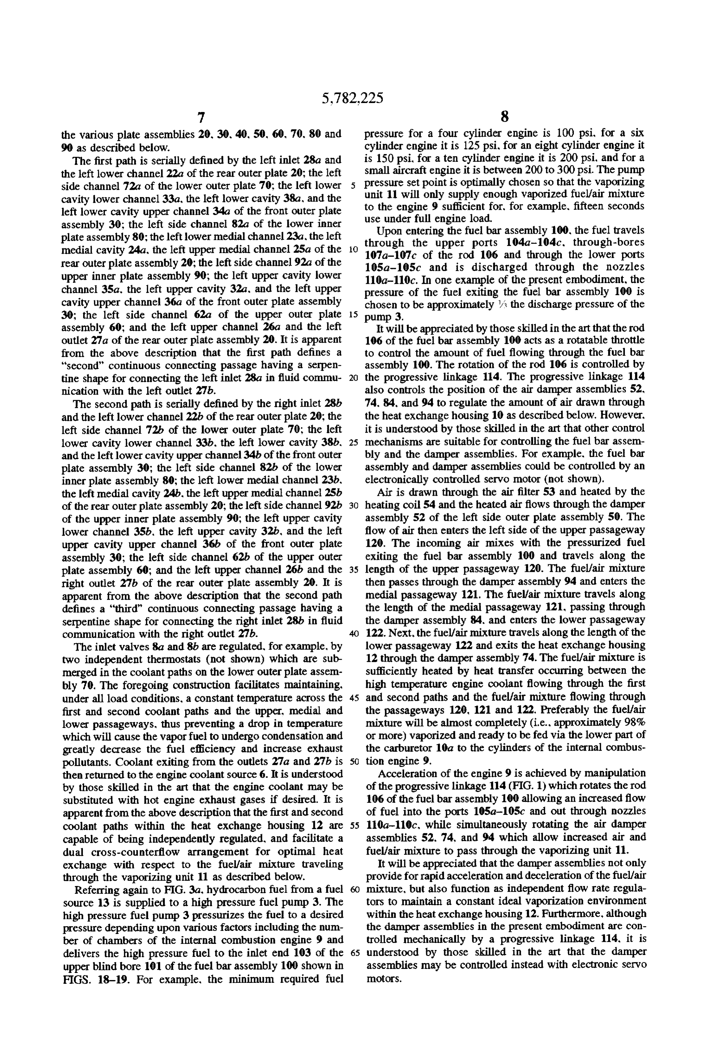
114 as described above for the damper assembly 52. Preferably, as shown in FIG. 19, the fluid bar assembly As shown in FIG. 17, the intermediate plate 91 of the 100 is provided with protrusions 112a and 112b formed upper inner plate assembly 90 includes a left side channel 35 along the top edge of the fluid bar assembly 100. Mating 92a extending through the entire height of the plate 91 and grooves (not shown) cut in the plate 61 matingly receive the a right side channel 92b also extending through the entire protrusions 112a and 112b of the fluid bar assembly 100 and height of the plate 91. The plate 91 further includes a facilitate the removal of the fluid bar assembly 100 from the discharge opening 93 within which is disposed a damper plate 61. It is also understood that the fluid bar assembly 100 assembly 94. The damper assembly 94 comprises a central can be formed integrally with the plate 61, with the rod 106 rod 95 and radially extending vanes 96 and 97. The damper permitted to rotate freely relative to the plate 61. assembly 94 is rotatably mounted within the discharge The operation of the fluid vaporization system 10 accord opening 93 and the central rod 95 extends past a frontal edge ing to the present invention will be described with an of the plate 91 for attachment to the progressive linkage 114 internal combustion engine with reference to FIGS. 3a and as described above for the damper assembly 52. 45 3b. In such an application, the mixture of fluids to be When assembled, as shown in FIGS. 1 and 2, the plate delivered to the internal combustion engine in a vaporized assemblies 20, 30, 40, 50, 60.70, 80 and 90 constitute the state comprises a mixture of liquid fuel and air, and the fluid heat exchange housing 12 of the vaporizing unit 11 and bar assembly 100 comprises a fuel bar assembly. provide three passageways therein: an upper passageway As shown schematically in FIG.3a, the vaporizing unit 11 120, a medial passageway 121, and a lower passageway 122. 50 of the present invention is attached to the bottom part of a The upper passageway 120 is defined by the lower side of conventional carburetor 10a. The top part of the conven the upper outer plate assembly 60 and the upper side of the tional carburetor, including the casing that contains the upper inner plate assembly 90. The medial passageway 121 choke assembly, is removed prior to attachment of the is defined by the lower side of the upper inner plate assembly vaporizing unit 11. In this arrangement, the air damper 90 and the upper side of the lower inner plate assembly 80. 55 assembly 74 disposed in the lower outer plate assembly 70 The lower passageway 122 is defined by the lower side of functions as the carburetor choke assembly. the lower inner plate assembly 80 and the upper side of the As shown in FIG. 3b, high temperature coolant from a lower outer plate assembly 70. The upper passageway 120, coolant source 6, preferably engine coolant, is pumped via the medial passageway 121, and the lower passageway 122 a pump 7 to a coil heater 5. The heater 5 heats the engine define a "first" continuous connecting passage having a coolant to approximately 180° F when and if required. Upon exiting the coil heater 5, the high-temperature coolant travels serpentine shape which connects the fluid inlet or bore 64 of the upper plate 61 and the inlet channel 59 of the left sideto inlet valves 8a and 8b such as, for example, conventional plate 51 in fluid communication with the discharge opening mechanical or electronic ball valves, which control the 73 of the lower plate 71. Preferably, the height of each amount of coolant passing therethrough into the left and passageway varies to accommodate expansion of the fluid 65 right inlets 28a and 28b, respectively, of the vaporizing unit traveling therein as a result of heating. For example, when 11. Upon entering the vaporizing unit 11, the high the vaporizing unit 11 is employed in combination with a temperature coolant travels in two adjacent paths defined by
Page 13
the various plate assemblies 20, 30.40, 50, 60, 70.80 and pressure for a four cylinder engine is 100 psi, for a six 90 as described below. cylinder engine it is 125 psi, for an eight cylinder engine it The first path is serially defined by the left inlet 28a and is 150 psi, for a ten cylinder engine it is 200 psi, and for a small aircraft engine it is between 200 to 300 psi. The pump the left lower channel 22a of the rear outer plate 20; the left pressure side channel 72a of the lower outer plate 70; the left lower unit 11 will set point is optimally chosen so that the vaporizing cavity lower channel 33a, the left lower cavity 38a, and the to the engineonly supply enough vaporized fuel/air mixture left lower cavity upper channel 34a of the front outer plate use under full engine load.for, for example, fifteen seconds 9 sufficient assembly 30; the left side channel 82a of the lower inner Upon entering the fuel bar assembly 100, the fuel travels plate assembly 80; the left lower medial channel 23a, the left through medial cavity 24a, the left upper medial channel 25a of the O 107a-107ctheof upper the rod ports 104a-104c. through-bores 106 and through the lower ports rear outer plate assembly 20; the left side channel 92a of the 105a-105c and is discharged through the nozzles upper inner plate assembly 90; the left upper cavity lower 110a-110c. In one example of the present embodiment, the channel 35a, the left upper cavity 32a, and the left upper pressure of the fuel exiting the fuel bar assembly 100 is cavity upper channel 36a of the front outer plate assembly chosen to be approximately /3 the discharge pressure of the 30; the left side channel 62a of the upper outer plate 15 pump 3.
assembly 60; and the left upper channel 26a and the left It will be appreciated by those skilled in the art that the rod outlet 27a of the rear outer plate assembly 20. It is apparent 106 of the fuel bar assembly 100 acts as a rotatable throttle from the above description that the first path defines a to control the amount of fuel flowing through the fuel bar "second" continuous connecting passage having a serpen assembly 100. The rotation of the rod 106 is controlled by tine shape for connecting the left inlet 28a in fluid commu the progressive linkage 114. The progressive linkage 114 nication with the left outlet 27b. also controls the position of the air damper assemblies 52, The second path is serially defined by the right inlet 28b. 74, 84, and 94 to regulate the amount of air drawn through and the left lower channel 22b of the rear outer plate 20; the the heat exchange housing 10 as described below. However. left side channel 72b of the lower outer plate 70; the left it is understood by those skilled in the art that other control lower cavity lower channel 33b. the left lower cavity 38b, 25 mechanisms are suitable for controlling the fuel bar assem and the left lower cavity upper channel 34b of the front outer bly and the damper assemblies. For example, the fuel bar plate assembly 30; the left side channel 82b of the lower assembly and damper assemblies could be controlled by an inner plate assembly 80; the left lower medial channel 23b, electronically controlled servo motor (not shown). the left medial cavity 24b, the left upper medial channel 25b Air is drawn through the air filter 53 and heated by the of the rear outer plate assembly 20; the left side channel 92b 30 heating coil 54 and the heated air flows through the damper of the upper inner plate assembly 90; the left upper cavity assembly 52 of the left side outer plate assembly 50. The lower channel 35b, the left upper cavity 32b, and the left flow of air then enters the left side of the upper passageway upper cavity upper channel 36b of the front outer plate 120. The incoming air mixes with the pressurized fuel assembly 30; the left side channel 62b of the upper outer exiting the fuel bar assembly 100 and travels along the plate assembly 60; and the left upper channel 26b and the 35 length of the upper passageway 120. The fuel/air mixture right outlet 27b of the rear outer plate assembly 20. It is then passes through the damper assembly 94 and enters the apparent from the above description that the second path medial passageway 121. The fuel/air mixture travels along defines a "third” continuous connecting passage having a the length of the medial passageway 121, passing through serpentine shape for connecting the right inlet 28b in fluid the damper assembly 84, and enters the lower passageway communication with the right outlet 27b. 122. Next, the fuel/air mixture travels along the length of the The inlet valves 8a and 8b are regulated, for example, by lower passageway 122 and exits the heat exchange housing two independent thermostats (not shown) which are sub 12 through the damper assembly 74. The fuel/air mixture is merged in the coolant paths on the lower outer plate assem sufficiently heated by heat transfer occurring between the bly 70. The foregoing construction facilitates maintaining, high temperature engine coolant flowing through the first under all load conditions, a constant temperature across the 45 and second paths and the fuel/air mixture flowing through first and second coolant paths and the upper, medial and the passageways 120, 121 and 122. Preferably the fuel/air lower passageways, thus preventing a drop in temperature mixture will be almost completely (i.e., approximately 98% which will cause the vapor fuel to undergo condensation and or more) vaporized and ready to be fed via the lower part of greatly decrease the fuel efficiency and increase exhaust the carburetor 10a to the cylinders of the internal combus pollutants. Coolant exiting from the outlets 27a and 27b is 50 tion engine 9.
then returned to the engine coolant source 6. It is understood Acceleration of the engine 9 is achieved by manipulation by those skilled in the art that the engine coolant may be of the progressive linkage 114 (FIG. 1) which rotates the rod substituted with hot engine exhaust gases if desired. It is 106 of the fuel bar assembly 100 allowing an increased flow apparent from the above description that the first and second of fuel into the ports 105a-105c and out through nozzles coolant paths within the heat exchange housing 12 are 55 110a-110c, while simultaneously rotating the air damper capable of being independently regulated, and facilitate a assemblies 52. 74, and 94 which allow increased air and dual cross-counterflow arrangement for optimal heat fuel/air mixture to pass through the vaporizing unit 11. exchange with respect to the fuel/air mixture traveling It will be appreciated that the damper assemblies not only through the vaporizing unit 11 as described below. provide for rapid acceleration and deceleration of the fuel/air Referring again to FIG. 3a, hydrocarbon fuel from a fuel mixture, but also function as independent flow rate regula source 13 is supplied to a high pressure fuel pump 3. The tors to maintain a constant ideal vaporization environment high pressure fuel pump 3 pressurizes the fuel to a desired within the heat exchange housing 12. Furthermore, although pressure depending upon various factors including the num the damper assemblies in the present embodiment are con ber of chambers of the internal combustion engine 9 and trolled mechanically by a progressive linkage 114, it is delivers the high pressure fuel to the inlet end 103 of the 65 understood by those skilled in the art that the damper upper blind bore 101 of the fuel bar assembly 100 shown in assemblies may be controlled instead with electronic servo FIGS. 18-19. For example, the minimum required fuel notors.
Page 14
Start-up of the engine 9 is accomplished by turning an inlet to the second discharge to effect transfer of heat ignition switch 4a to the ON position. Arelay 4b is energized energy between the third fluid and the fluid mixture to and activates a low pressure fuel pump 2. The fuel pump 2 vaporize the fluid mixture and discharge the mixture by pumps fuel to the lower part of the carburetor 10a since the the first discharge in a vaporized state; and a controller engine must start on liquid fuel and the vaporizing unit 11 disposed between at least two of the first connecting will not function effectively until it has reached a proper passages for controlling the amount of fluid mixture operating temperature. Accordingly, the relay 4b simulta delivered from one connecting passage to another and neously activates the air heating coil 54 and the coolant to the first discharge.
heating coil 5 to rapidly achieve a minimum operating 2. A fluid vaporization system as claimed in claim 1, temperature (i.e. approximately 150°F) of the vaporizing 10 wherein each of the controllers comprises a rotatable rod having radially extending vanes, the rotating rod being unit 11. As the engine 9 achieves its normal operating rotatable temperature and thusly raises the temperature of the engine extendingbetween a first position. in which the radially coolant to approximately 190 F. dependence on the air connectingvanes permit the fluid mixture to flow through the passages, and a second position, in which the heating coil 54 and the coolant heating coil 5 is reduced. radially extending vanes block the flow of the fluid mixture When the minimum operating temperature of the vaporizing 15 through the connecting passages. unit 11 is sensed by a temperature sensing array 4d, the relay 3. A fluid vaporization system comprising: 4b deactivates the low pressure fuel pump 2 and activates the an upper plate;
high pressure fuel pump 3 which begins pumping fuel to the a lower plate;
fuel bar assembly 100. The vaporizing unit 11 maintains its a plurality of side plates interconnecting the upper plate optimal operating temperature of approximately 190° F via and the lower plate in spaced relation to define a sealed the temperature sensing array 4d which controls the tem chamber;
perature of the air heating coil 54 and the coolant heating first inlet means disposed in the upper plate for receiving
Stopping of the engine 9 is accomplished by turning the a first fluid;
ignition switch 4a to the OFF position, which activates a 25 second inlet means disposed in a first one of the side timer 4c, deactivates the high pressure fuel pump 3, and plates for receiving a second fluid; activates the low pressure fuel pump 2. The timer 4c keeps first discharge means disposed in the lower plate for the engine 9 running for a sufficient time, approximately 15 discharging the first fluid and the second fluid; seconds, to allow all of the vaporized fuel in the vaporizing third inlet means disposed in a second one of the side unit 11 to be consumed by the engine 9 and for the bottom 30 plates for receiving a third fluid; part of the carburetor 10a to fill with liquid fuel. This second discharge means disposed in the second side plate delayed shut-off process serves to eliminate accidental deto for discharging the third fluid; nation of the vaporized fuel in the vaporizing unit 11 after at least one intermediate plate disposed within the sealed engine shut-off and prepares the engine 9 for a subsequent chamber and connected to the side plates to define first start-up. 35 connecting passage means connecting the first inlet From the foregoing description, it can be seen that the means and the second inlet means in fluid communi present invention comprises an improved fluid vaporization cation with the first discharge means for mixing the first system. It will be appreciated by those skilled in the art that fluid and the second fluid to define a fluid mixture and obvious changes could be made to the embodiment delivering the fluid mixture to the first discharge described in the foregoing description without departing means; and from the broad inventive concept thereof. For example, aperture means disposed in the upper plate, the lower although the foregoing embodiment of the fluid vaporization plate, the side plates and the intermediate plate and system has been described with a specific application to an defining second connecting passage means in heat internal combustion engine, it will be appreciated that the transfer relationship with the first connecting passage fluid vaporization system is also well adapted for other 45 means connecting the third inlet means in fluid com applications, such as, for example, heating oil fuel munication with the second discharge means for deliv processors, air conditioning systems, refrigeration systems ering the third fluid from the third inlet means to the and ice storage tanks. It is understood, therefore, that this second discharge means to effect heat transfer from the invention is not limited to the particular embodiment third fluid to the fluid mixture to effect vaporization of disclosed, but is intended to cover all modifications thereof SO the fluid mixture and discharge thereof by the first which are within the scope and spirit of the invention as discharge means in a vaporized state. defined by the appended claims. 4. A fluid vaporization system as claimed in claim 3; What is claimed is: wherein each of the first connecting passage means and the 1. A fluid vaporization system comprising: second connecting passage means defines a fluid flow pas a first inlet for receiving a first fluid; a second inlet for 55 sage which is serpentine in shape. receiving a second fluid; a first discharge for discharg 5. A fluid vaporization system as claimed in claim 3: ing the first fluid and the second fluid; a plurality of first further comprising fourth inlet means for receiving the third interconnected passages connecting the first inlet and fluid and third discharge means for discharging the third the second inlet in fluid communication with the first fluid; the aperture means defining third connecting passage discharge for mixing the first fluid and the second fluid means in heat transfer relationship with the first connecting to form a fluid mixture and delivering the fluid mixture passage means for connecting the third inlet means in fluid to the first discharge; a third inlet for receiving a third communication with the second discharge means and deliv fluid; a second discharge for discharging the third fluid; ering the third fluid from the fourth inlet means to the second a second connecting passage in heat transfer relation discharge means.
ship with the first connecting passages and connecting 65 6. A fluid vaporization system as claimed in claim 5; the third inlet in fluid communication with the second wherein the third connecting passage means defines a fluid discharge for delivering the third fluid from the third passage which is serpentine in shape.
Page 15
7. A fluid vaporization system as claimed in claim 3; rotatable between a first position, in which the radially further comprising first controlling means for controlling the extending vanes permit the fluid mixture to flow through the amount of the first fluid which enters the first connecting first passages, and a second position in which the radially passage means; second controlling means for controlling the extending vanes block the flow of the fluid mixture through amount of the second fluid which enters the first connecting 5 the first passages.
passage means; and third controlling means for controlling 12. A fluid vaporization system comprising: the amount of the third fluid which enters the second connecting passage means. first connecting passages which receive a first fluid and a 8. A fluid vaporization system comprising: second fluid for mixing the first fluid and the second O fluid to form a fluid mixture and discharges the fluid first connecting passages which receive a first fluid and a mixture;
second fluid for mixing the first fluid and the second second connecting passages which receive and discharges fluid to form a fluid mixture and discharges the fluid a third fluid, the second passages being in heat transfer mixture;
second connecting passages which receive and discharges 15 relationship with the first passages and defining a a third fluid. the second passages being in heat transfer serpentine cross-counterfiow heat exchanger to effect relationship with the first passages and defining a transfer of heat energy from the third fluid to the fluid serpentine cross-counterflow heat exchanger to effect mixture to vaporize the fluid mixture and discharge the transfer of heat energy from the third fluid to the fluid fluid mixture in a vaporized state; mixture to vaporize the fluid mixture and discharge the 20 a first controller for controlling the amount of the first fluid mixture in a vaporized state; fluid which enters the first passages; a first controller for controlling the amount of the first a second controller for controlling the amount of the fluid which enters the first passages, the first controller second fluid which enters the first passages, the second comprising a first bore for receiving the first fluid, a controller comprising a rotatable rod having radially second bore in fluid communication with the first bore 25 extending vanes, the rotatable rod being rotatable and the first passages. and a rotatable rod having a between a first position, in which the radially extending radial bore and being rotatably disposed within the vanes permit the second fluid to flow into the first second bore, the rotatable rod being rotatable between passages, and a second position, in which the radially a first position, in which the radial bore is in fluid extending vanes block the flow of the second fluid into communication with the first bore such that the first the first passages;
fluid is permitted to flow into the first passages and a a third controller for controlling the amount of the third second position in which the radial passage is not in fluid which enters the second passages. fluid communication with the first bore such that the 13. A fluid vaporization system as claimed in claim 12. first fluid is prevented from flowing into the first wherein the third controller comprises a fluid control valve. passages: 35 14. A fluid vaporization system as claimed in claim 12. a second controller for controlling the amount of the further comprising a fourth controller disposed in the first second fluid which enters the first passages; passages for controlling the amount of fluid mixture dis a third controller for controlling the amount of the third charged therefrom.
fluid which enters the second passages. 15. A fluid vaporization system as claimed in claim 14. 9. A fluid vaporization system as claimed in claim 8. wherein the fourth controller comprises a rotatable rod wherein the third controller comprises a fluid control valve. having radially extending vanes, the rotatable rod being 10. A fluid vaporization system as claimed in claim 8. rotatable between a first position, in which the radially further comprising a fourth controller disposed in the first extending vanes permit the fluid mixture to flow through the passages for controlling the amount of fluid mixture dis first passages, and a second position in which the radially charged therefrom. 45 extending vanes block the flow of the fluid mixture through 11. A fluid vaporization system as claimed in claim 10, the first passages.
wherein the fourth controller comprises a rotatable rod having radially extending vanes, the rotatable rod being
Provenance
- Collection
- Cited prior art
- Original PDF
- patentimages.storage.googleapis.com →
- Filed
- 1997-11-21
- Pages
- 15
- Method
- pdftotext (the PDF's own text layer) + pdftoppm 300dpi page scans
- Source
- Google Patents bibliographic record
- Granted
- 1998-07-21
- Inventors
- Allen Caggiano
- Transcribed from
- patentimages.storage.googleapis.com →