patent · US4862859
Apparatus and operating method for an internal combustion engine
5 September 1989
Page 1 — bibliographic record
United States Patent (19) 11 Patent Number: 4,862,859 Yunick 45 Date of Patent: * Sep. 5, 1989 (54) APPARATUS AND OPERATING METHOD Primary Examiner-Tony M. Argenbright FOR AN INTERNAL COMBUSTON ENGINE Attorney, Agent, or Firm-Watts, Hoffmann, Fisher & Heinke Co.
(76 Inventor: Henry Yunick,957 N. Beach St.,
Daytona Beach, Fla. 32017 57 ABSTRACT * Notice: The portion of the term of this patent A method and apparatus for operating an electric igni subsequent to Mar. 12, 2002 has been tion, internal combustion engine that substantially im disclaimed. proves the fuel efficiency by utilizing heat normally (21 Appl. No.: 191,717 discharged to the ambient to condition and prepare the
fuel mixture prior to entry into the combustion cham bers. The apparatus comprises a fuel vaporizer that
Related U.S. Application Data transfers heat from the engine coolant system to the fuel mixture as it leaves a fuel introducing device such as a 60 Continuation of Ser. No. 869,864, Jun. 2, 1986, aban carburetor; a fuel mixture heater for heating the mixture doned, which is a division of Ser. No. 623,053, Jun. 21, above the vaporization temperature of the liquid fuel; 1984, Pat. No. 4,592,329. and, a mixture homogenizer for thoroughly stirring the 51 Int. Cl* ...................................... FO2M 31/08 fuel mixture that is located in the fuel mixture flow path 52 U.S. C. .................................................... 123/545 intermediate the vaporizer and heater. The homoge 58 Field of Search ................... 123/543, 545; 60/599 nizer is operative to compress the fuel mixture under 56 References Cited certain engine operating conditions and the heater forms the intake manifold for the engine and includes
Re. 22,962 l/1948 Oswald ........................... 123/547 X nicate directly with each combustion chamber through 1,335,665 3/1920 Deppe ....... ... 123/592 X a valve controlled port. The fuel mixture flow path 1,885,697 11/1932 Fabbro ................................ 123/592 from the homogenizer is constructed to minimize en 2,216,722 0/1940 Denson ............. ... 123/592 X ergy losses to the ambient.
4,338,906 7/1982 Cox ........... ... 123/545 4,503,833 3/1985 Yunick ................................ 123/545 11 Claims, 10 Drawing Sheets
EXHAUST
FUEL MIXTURE
HEATER
Page 2
Drawing sheet — no readable text.
Page 3
Drawing sheet — no readable text.
Page 4
Drawing sheet — no readable text.
Page 5
Drawing sheet — no readable text.
Page 6
Drawing sheet — no readable text.
Page 7
Drawing sheet — no readable text.
Page 8
Drawing sheet — no readable text.
Page 9
Drawing sheet — no readable text.
Page 10
Drawing sheet — no readable text.
Page 11
Drawing sheet — no readable text.
Page 12
The addition of
APPARATUS AND OPERATING METHOD FOR engine fuel efficiency in normal automotivea turbocharger has not increased AN INTERNAL COMBUSTON ENGINE usage. In This application is a continuation of application Ser. less friction to be used in a given size vehicle. with general, the turbocharger allows a smaller engine
No. 869,864, filed 6/26/86, now abandoned, which is as With these prior engines under operating conditions division of application Ser. No. 623,053, filed June 21, where cylinder intake produces high vacuum, pressure 1984, now U.S. Pat. No. 4,592,329. from the ambient air on the intake side of the turbo TECHNICAL FIELD charger may exceed manifold pressure thus creating a pressure differential across the compressor side of the
The present invention relates generally to electrici 10 turbocharger. When an engine is idling there is little ignition, internal combustion engines each of which exhaust flow to drive the turbine and high vacuum functions as an expander during a portion of a cycle and manifold conditions exist so there is a large pressure in particular to a new and improved fuel system and differential across the compressor side of the turbo engine operating method. charger. This pressure differential causes an air flow 15 through the compressor side. This air flow applies rota
BACKGROUND ART
tional forces to the compressor blade in opposition to
In conventional gasoline engines, particularly those the drive turbine.
used in the automotive industry, a carburetor mounted Because exhaust flow is low, the air flow produced atop an intake manifold forms the principal component forces may be sufficient to cause reverse rotation of the of a fuel system. As is well known, combustion air is 20 compressor and will in any event prevent effective drawn through the carburetor. A controlled amount of turbocharger operation. Thus, under light load the tur gasoline is added to the incoming air to form a combus bocharger is essentially inoperative and in fact may run tible fuel/air mixture, as the air passes through a venturi backwards.
throat formed in the carburetor. The intake manifold, Another problem with each prior engine with a tur which includes passages that communicate with valve 25 bocharger controlled intake ports in the cylinder head of the en fold occursbetween its carburetor and its intake mani gine, conveys and distributes the fuel/air mixture from is increased, the quantity ofWhen on acceleration.
liquid the throttle opening fuel droplets con the carburetor to the combustion chambers.
In theory, the liquid gasoline is vaporized prior to tained in the fuel/air mixture is increased virtually in entering the combustion chambers. In practice, how 30 stantaneously but exhaust flow is not. This additional liquid fuel causes a significant increase in the load on the ever, a major portion of the gasoline remains unvapor compressor turbine. Indeed in test racing engines the ized and in a liquid state even as it enters the combustion chamber, finally vaporizing during the combustion pro load increases on occasion, have been great enough to cess. The presence of unvaporized fuel in the combus cause force compressor turbine destruction. Since the driving from exhaust gases is substantially constant the tion chamber, reduces the heat of combustion, thus compressor
is slowed by this load increase and the com limiting the power output of the engine.
It has long been recognized that the efficiency of the pressing action of the turbocharger is reduced. In time gasoline engine is substantially less than ideal. One fac the increased fuel produces increased exhaust gases, tor contributing to poor efficiency in some engines is causing put. In the turbocharger to increase its speed and out sum, prior turbocharged engines have slow re known as carburetor "double pull'. Since the intake sponse to demands for power increases and will con port is usually opened well before the exhaust stroke is completed, gases are forced in a reverse direction sume excessive fuel for a time whenever there is a signif. through the carburetor venturi drawing fuel into this icantconsumption increase in throttle opening. In fact, this excessive flow. This reverse flow goes into the air inlet and filter fuelfor prior has made it difficult, if not impossible, turbocharged engines to meet Environmental wasting fuel. Another factor is a substantial portion of 45 the energy available in each pound of gasoline con inProtection Agency (EPA) standards if the turbocharger fact operates during testing.
sumed by an engine, is discharged to the ambient as Other proposals for increasing the fuel efficiency of waste heat from its cooling and exhaust systems and by way of radiation from the engine. Automotive designers gasoline engines have included methods and apparatus over the years have proposed methods and apparatus 50 for heating the fuel to aid vaporization. Prior proposals for recapturing and utilizing at least a portion of this have suggested heating the fuel-air mixture by transfer waste heat. ring heat from either the engine cooling system or the One proposed apparatus is an exhaust driven super engine exhaust system. Problems associated with heat charger, more commonly called a turbocharger. A tur ing a fuel/air mixture as it travels to a combustion bocharger generally comprises a pair of turbines. 55 chamber, have long been recognized.
mounted to a common shaft. One turbine is a drive These problems include an increase in the tempera turbine disposed in an exhaust flow path, while the ture of the fuel mixture decreases the mixture density other turbine is a compressor turbine disposed, at least and causes a decrease in the volumetric efficiency of the in some instances, in the intake flow path between the engine for it decreases the amount of fuel drawn into carburetor and the combustion chambers. In this config 60 each cylinder during an intake stroke. In addition, heat uration, the exhaust gases discharged by the combustion ing the fuel often causes a vapor lock condition in the chambers expand across the exhaust turbine to rotate it. fuel system which partially or completely blocks the and the intake turbine thereby compressing gases in the flow of fuel into the intake flow path, degrading engine fuel air mixture. This compression permits an increase in performance. To avoid vapor lock, many of the pro the amount of fuel introduced into each piston cylinder 65 posed fuel mixture heaters operate during engine during the intake stroke of its piston while maintaining warmup only and are turned off once the engine reaches a desired fuel/air ratio, to produce an attendant increase its operating temperature. Further, prior hot vapor in the engine's power output. engine proposals have utilized storage chambers from
Page 13
which the fuel air mixture is modulated. Such a cham such as gasoline, with combustion air in controlled ber is large and can be dangerous. proportions. The apparatus utilizes heat normally ex With prior engines, during engine warmup, vapor hausted by the engine to condition the fuel mixture. The ized fuel condensed on the interior walls of the intake apparatus prepares and conditions the fuel/air mixture manifold and other surfaces. Manifold and carburetor during its laminar flow travel to the engine combustion heating systems have been proposed to operate during chambers to insure complete fuel vaporization and thor engine warmup and were intended to solve or minimize ough fuel/air mixing so that maximum energy output is this problem. While such proposals might improve con realized during the combustion process. ditions during warmup, the fuel still experienced as In the preferred embodiment, a fuel mixture flow many as four phase changes as it travelled from the O path is defined that extends between a fuel mixture carburetor to the combustion chambers, even in an introducing device, such as a carburetor and the engine engine that had reached its operating temperature. Spe combustion chambers. The flow path communicates cifically, portions of the fuel entrained in the mixture with each combustion chamber through an associated flow shift between vapor and liquid states as the mixture valve controlled port. The apparatus further comprises travels through the engine intake system. Moreover, 15 an air heater and fuel/air mixture vaporizing and heat these phase change characteristics in a multi-cylinder ing devices disposed in the flow path, and a fuel mixture engine are uneven varying from cylinder to cylinder homogenizer located between the fuel mixture vaporiz and further varying with engine speed and load. ing and heating devices. While tests of the present in These phase changes contribute to the reduction in vention have been conducted using a conventional car thermal efficiency in an engine due to: (1) the induction 20 buretor, it is believed that the operation of the apparatus of some liquid fuel into the combustion chambers; (2) does not depend on the use of a carburetor; alternate the nonuniform nature of the fuel-air mixture; and (3) methods for introducing fuel into an air flow path such substantial heat energy losses to the intake manifold and as pressure carburetion and manifold injection are also other components of the fuel system. These losses are contemplated.
substantial because gasoline, like all liquids, has a rela 25 In the preferred embodiment, the fuel mixture vapor tively high heat of vaporization. izer includes a chamber disposed in the flow path inter The prior proposals for increasing the thermal effi mediate the carburetor and the fuel mixture homoge ciency of an engine have not recognized or addressed nizer that is heated by fluid from an engine cooling this problem. In most of the proposed systems, the fuel system. The heat absorbed by the engine cooling sys or fuel mixture was merely to be heated by either fluid 30 tem, which in the past has been wasted, is transferred to from the engine cooling system or alternately by ex the incoming fuel mixture as it passes through the va haust gases. porizer chamber thereby enhancing fuel vaporization Combining a turbocharger with a fuel mixture heat and producing an at least partially vaporized mixture. ing apparatus has been proposed in the past. In one such The mixture is then directed to the fuel mixture ho proposal, the fuel charge would be heated by exhaust 35 mogenizer which stirs and further heats the mixture so gases during part throttle operating conditions only. that the fuel is fully vaporized to a superheated vapor During full throttle conditions, the exhaust gases would state or "supervaporized' state and the vapor is uni be diverted to a turbocharger and the fuel mixture formly dispersed as a homogenous mixture of fuel vapor would go unheated, so that its density would be maxi and air.
mized. The preferred homogenizer is exhaust driven and It has also been found that many engine designers are includes a pair of turbines mounted on a common shaft of the opinion that the fuel mixture should be cooled and rotatably supported in a structure that defines sepa after leaving a turbocharger or a supercharger. A cool rate turbine chambers. One turbine is an exhaust drive ing device commonly called an “intercooler' is dis turbine and it, in turn, drives the other turbine which is posed between the outlet of the supercharger and the 45 an homogonizing turbine disposed in the fuel mixture combustion chambers. The purpose of the intercooler is flow path. The turbines are sized to provide both mix to remove the heat generated as the mixture is com ing and mixture pressurization at all throttle openings. pressed so that the fuel mixture density is increased. Unlike the prior art turbochargers, the homogenizer These seemingly conflicting proposals would indicate functions throughout the engine operating range insur that confusion and uncertainty still exist in fuel system 50 ing thorough fuel vaporization and mixing and disper design theory. sion of the fuel uniformly throughout the air of the The measure of success, however, in increasing the mixture. One major reason the homogenizer functions fuel efficiency of an internal combustion engine does throughout the engines operating range is that the fuel not reside in the complexity or simplicity of the appara /air mixture is temperature expanded across the homog tus or the rigid adherence to long taught engine design 55 enizing turbine applying rotational force additive to the principals, but in the increase in gasoline mileage and exhaust gas produced forces.
engine performance actually achieved in a given size In one version of the engine the heated homogenizer engine. housing defines intake air flow passages which are con DISCLOSURE OF INVENTION nected to the carburetor air intake by a hot air conduit. Air is heated as it passes through these passages. A
The present invention provides a new and improved temperature responsive valve closes off an ambient air apparatus and method for improving the fuel efficiency inlet to the carburetor whenever air supplied by the hot of an electric ignition, internal combustion engine. It is air conduit is below about 110 F. and manifold vacuum readily adaptable to existing automobile engines for it is above four inches.
does not require excessive engine retooling and it will 65 An EGR system is provided in the version of the decrease the cost and weight of the vehicle. engine which has preheated air. Unlike prior EGR According to the invention, a fuel charge forming systems, the system of the present invention assures apparatus is disclosed for combining a vaporizable fuel, uniform distribution of recalculated exhaust and vapori
Page 14
zation of residual hydrocarbons. This uniformity is ac The disclosed apparatus recaptures heat normally complished by introducing the EGR fluids to the fuel wasted from both the engine cooling system and the /air mixture flow path at or ahead of the entrance to the engine exhaust system and utilizes this heat to com homogenizer. As these residuals are passed through the pletely vaporize and thoroughly mix the fuel mixture. homogenizer they are thoroughly admixed with the As a result, the size of the vehicle radiator can be signifi fuel/air mixture assuring for the first time uniform dis cantly reduced and the need for a radiator fan is elimi tribution of the residuals among the combustion cham nated.
bers. Normally, the coolant radiator is necessary to pro Since the fuel/air mixture is preheated before it is 10 vide the means for discharging the waste heat absorbed introduced into the homogenizer its specific density is by the engine coolant. In the present invention, the low and little, if any, unvaporized fuel is present. Thus waste heat is transferred and absorbed by the vaporiz the fuel air mixture is comparatively easy to compress ing fuel. The heat absorbed by the fuel reduces the and continuous compression of its output can and does coolant temperature and thus supplants a significant occur at all engine speeds. In addition the outlet from 15 partAdditionally, of the radiator function.
the chamber is somewhat restricted to partially isolate are sized so thatthe the coolant system conduits and pump coolant flow rate through the en the homogenizer's mixing chamber from pressure dif gine is linear with the ferentials between the input and output sides of the requisite amount of heatengine output to provide the to the fuel mixture vaporizer.
homogenizer which occur during power demand condi According to another feature of the invention, an tions and prevents a "double pull” on the fuel supply. 0 isolator is positioned between the carburetor and the This isolation coupled with the low specific density of fuel mixture homogenizer. The purpose of the isolator is the fuel/air mixture and the mixtures thermal expansion to inhibit direct, uncontrolled heat conductivity along permit the homogenizer to function efficiently during the mixture flow path to the base and thence to the bowl acceleration. Thus, the homogenizer operates at idle conditions and response lag is not experienced during 25 ofof the carburetor. The isolator minimizes the incidence vapor lock that might occur in the carburetor when accelerating conditions. a "hot' engine is turned off. The isolator inhibits the The fuel mixture heater is disposed in the mixture transmission of engine heat to the bowl of the carbure flow path between the outlet of the homogenizer and tor through the structure that defines the mixture flow the intake ports of the engine. In the preferred embodi path.
ment, the fuel mixture heater includes an exhaust heated 30 In a more specific embodiment, the isolator comprises chamber through which the mixture passes on its way an elastomeric, nonconductive coupling between the to the combustion chamber. The heater insures that the outlet of the engine preheater and the inlet to the ho fuel remains in its completely vaporized state, prefera mogenizer. In this preferred embodiment, the carbure bly at a temperature twice the vaporization temperature tor and vaporizer are mounted to the vehicle chassis or of the fuel, prior to entering the combustion chamber. 35 body and hence the isolator prevents not only the trans It is believed that automobile engines presently being mission of heat to the carburetor but engine vibration as manufactured can be modified or adapted to utilize the well. It is believed the vibration isolation provided by present invention and thereby realize a substantial gain this isolator construction and carburetor mounting in in fuel efficiency. Some conventional components are creases the reliability of the carburetor, prevents loss of eliminated and those components which are used do not fuel flow control due to vibration, and should reduce require exotic materials, extensive engine retooling or the incidence of carburetor readjustment. complicated manufacturing processes. In addition, The present invention discloses a method for operat smaller engines can be standard equipment in present ing an engine in which all the fuel is fully vaporized automobiles to decrease their cost and weight. before it is introduced into the combustion chamber and According to the exemplary and illustrated embodi 45 once vaporized remains vaporized and fully homoge ment, the fuel mixture vaporizer comprises a housing nously mixed with air as it is conducted through the that also serves as a mounting base for the carburetor. engine intake system. The fuel is not only completely The housing defines an interior chamber that communi vaporized but is also thoroughly mixed so that a uni cates with the throat of the carburetor and an outlet form fuel and air mixture enters the combustion cham conduit that conveys the fuel mixture from the chamber 50 ber. According to the method, the fuel, such as gasoline, to the homogenizer. Coolant passages, located in the is entrained in a flow of atmospheric air. The entrained walls of the housing, support coolant flow between an fuel and air, forming a somewhat non-homogenous fuel inlet and an outlet forming part of the vaporizer. Suit mixture is preheated by heat derived from the engine, able conduits communicate the coolant inlet and outlet i.e., from either the engine cooling or engine exhaust with the engine cooling system. A small radiator is 55 system. The fuel and atmospheric air is then mixed by a coupled in parallel with the vaporizer. A thermostati homogenizer to produce a uniform fuel/air mixture. cally controlled valve blocks flow to the radiator when The homogenous mixture is then further heated to a ever coolant temperature is below about 200' F. temperature well in excess of, preferably at least twice, The fuel mixture heater comprises a housing that the vaporization temperature of the fuel and then it is includes passages in the side walls through which ex 60 introduced, virtually immediately, into a combustion haust gases travel and heat the interior walls of the chamber.
plenum. According to a feature of this embodiment, the In order to take full advantage of the fuel preparation chamber includes vertically standing ribs which subdi apparatus and method disclosed above, the present in vide the mixture flow into a plurality of branch flow vention also provides additional method steps for oper paths, the number of which corresponds to the number 65 ating an engine to optimize the amount of energy ex of cylinders in the engine. Conduits direct exhaust gases tracted from the fuel charge inducted into the combus from the combustion chambers to the passages formed tion chamber. This optimizes the power output of the in the walls of the plenum chamber. engine and reduces the amount of heat which must be
Page 15
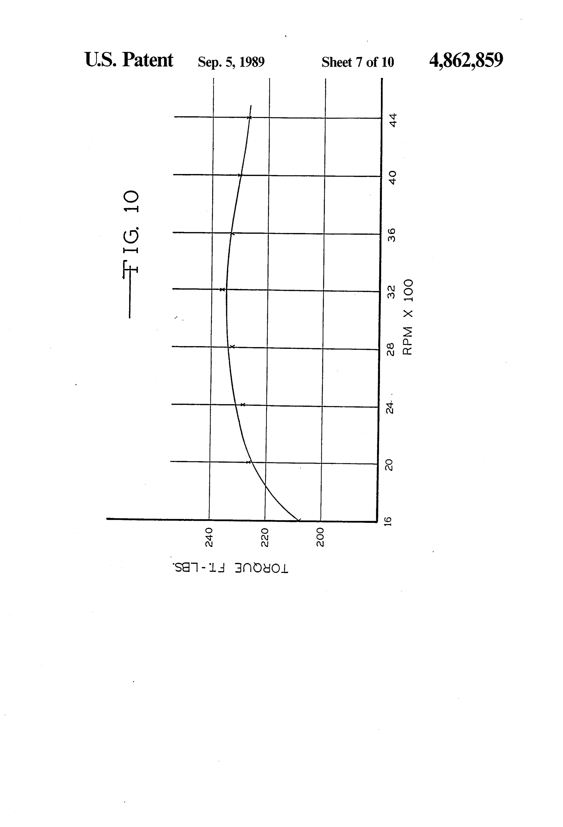
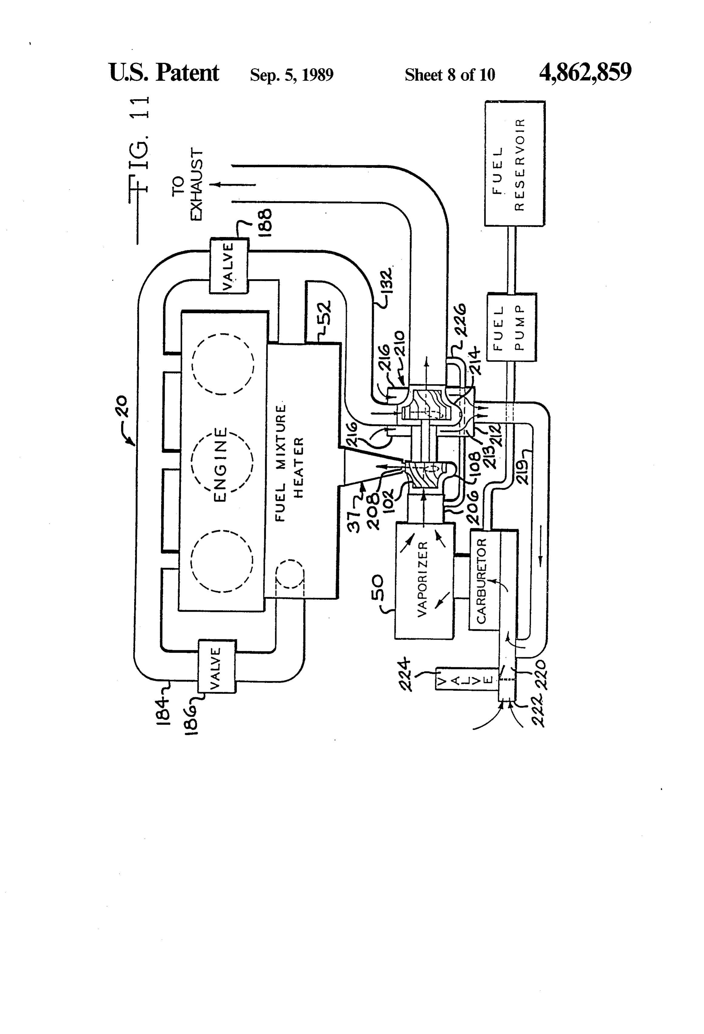
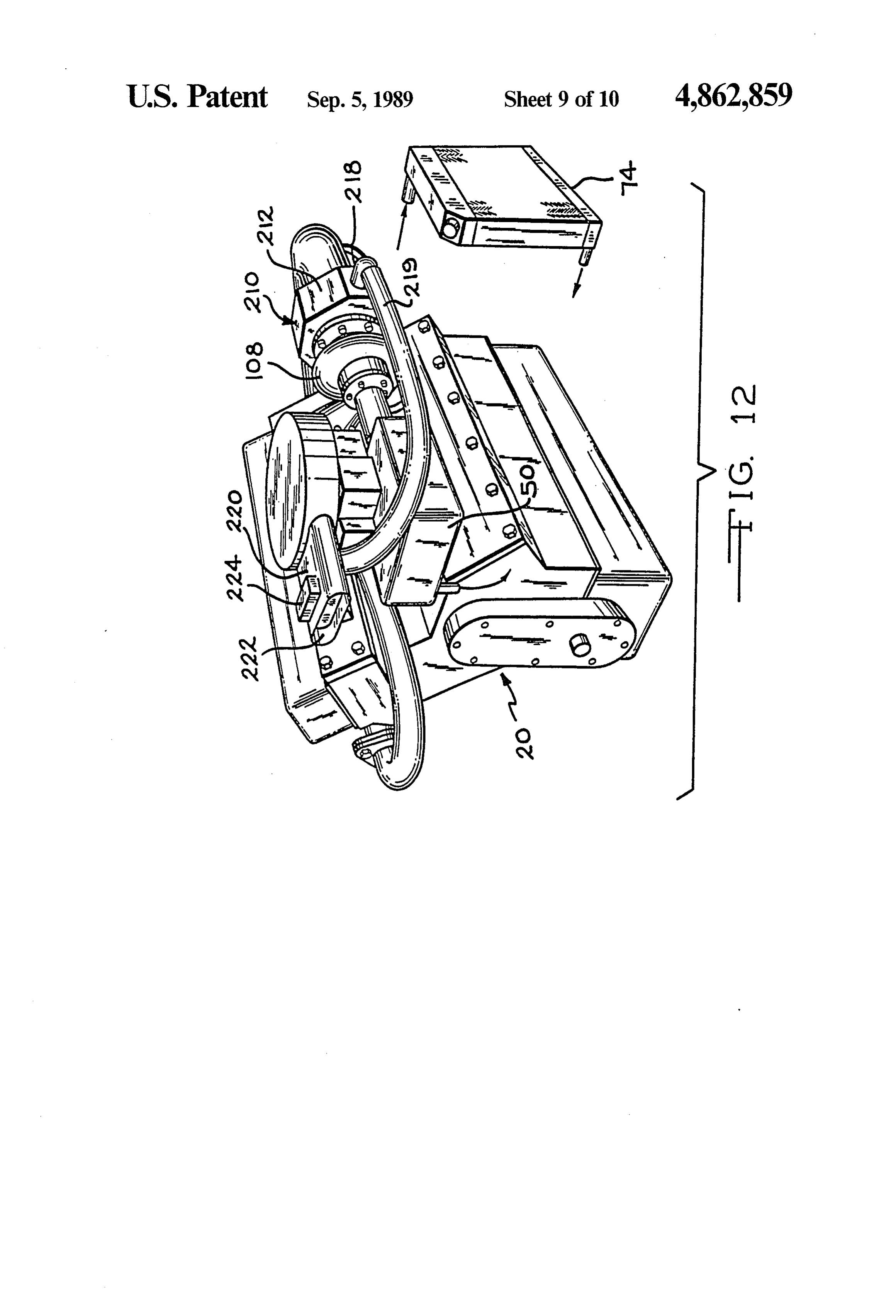
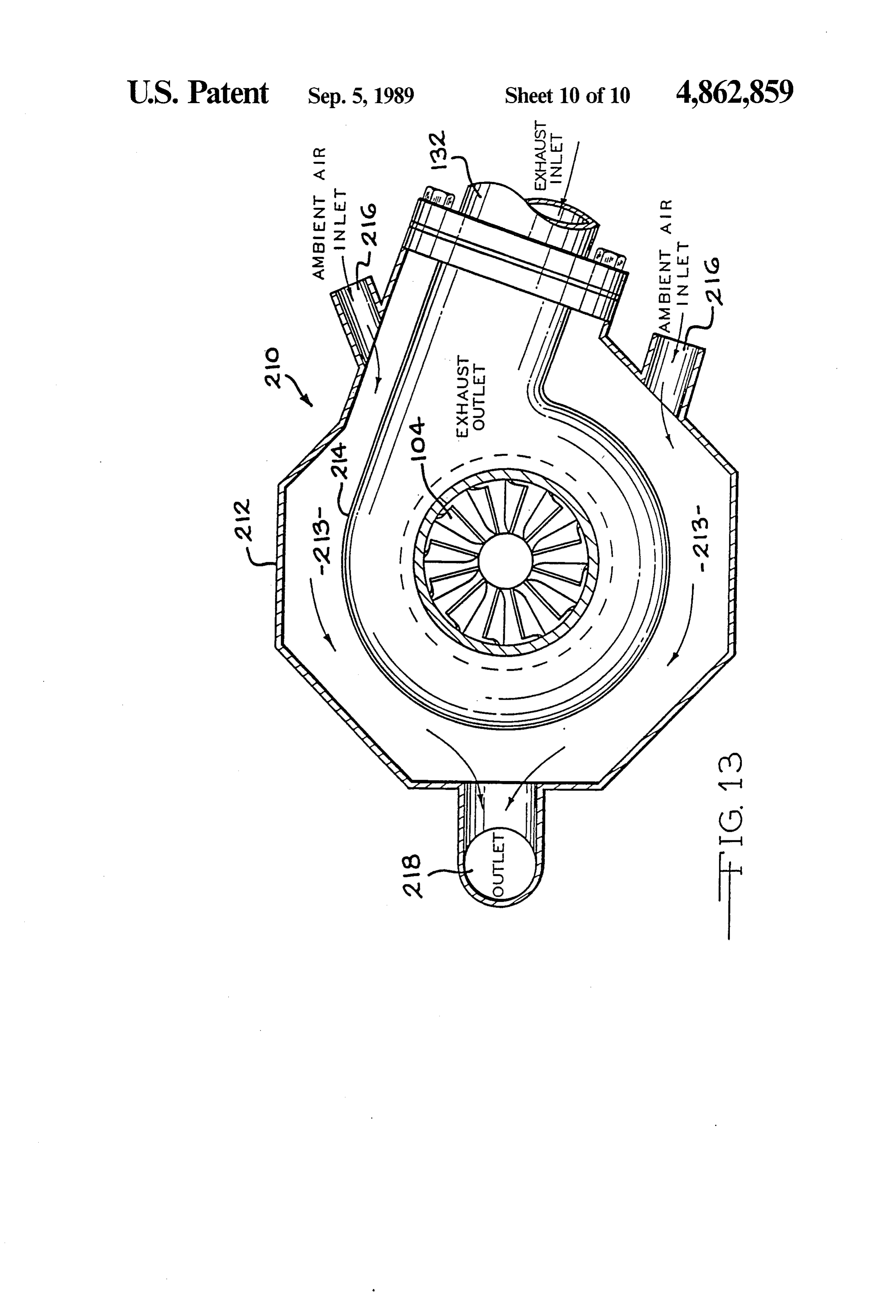
taken out with a cooling system thus contributing to the FIG. 10 is a graph depicting a measured torque curve reduction in radiator size. According to these additional of the engine of this invention; method steps, the volume of the combustion chamber is FIG. 11 is a schematic view of a refined version of the held substantially constant during the combustion pro engine of this invention;
cess until the gases and products of the combustion FIG. 12 is a perspective view of the engine of FIG. reaction substantially reach their maximum temperature 11; and and pressure. In order to accomplish these method FIG. 13 is an enlarged sectional view of the homoge steps, the crankshaft stroke and piston rod length are nizer of the engine of FIGS. 11 and 12. selected so that the piston remains within 0.001 inches 10 BEST MODE FOR CARRYING OUT THE of top-dead-center (TDC) for at least 13 of crankshaft INVENTION rotation.
It is believed that the disclosed fuel charge forming The present invention provides a new and improved apparatus used in connection with the engine operating fuelapparatus and method for substantially improving the method disclosed by the present invention provides an 15 tion efficiency engine. In of an electric ignition, internal combus accordance with the invention, engine engine that functions as an "expander', that is, an en heat normally discharged to the ambient by the exhaust gine in which all useful expansion forces generated and coolant systems is captured during combustion are utilized for producing motion in and condition the incoming fuelandmixture utilized to prepare the piston and to a significant extent, are not dissipated creased combustion efficiency is realized. Insoparticular, that in as heat losses. Maintaining the piston virtually at TDC until, the combustion temperature and pressure are opti 20 the the present invention thoroughly mixes and vaporizes incoming fuel charge prior to entry into the engine mized assures that the heat energy generated is primar combustion chambers.
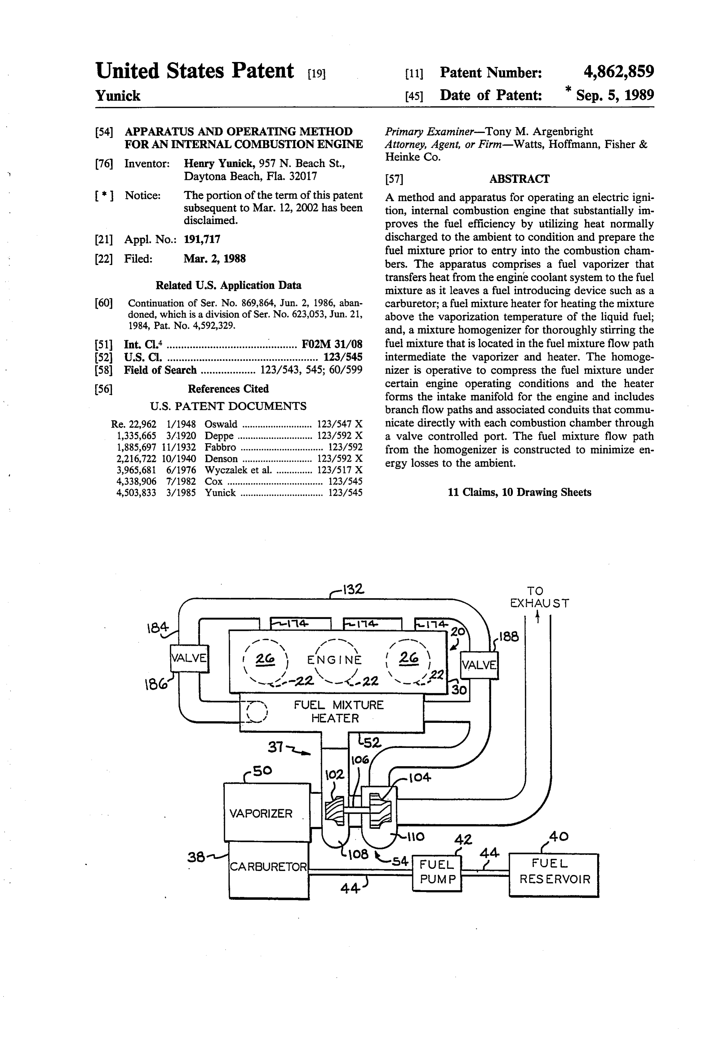
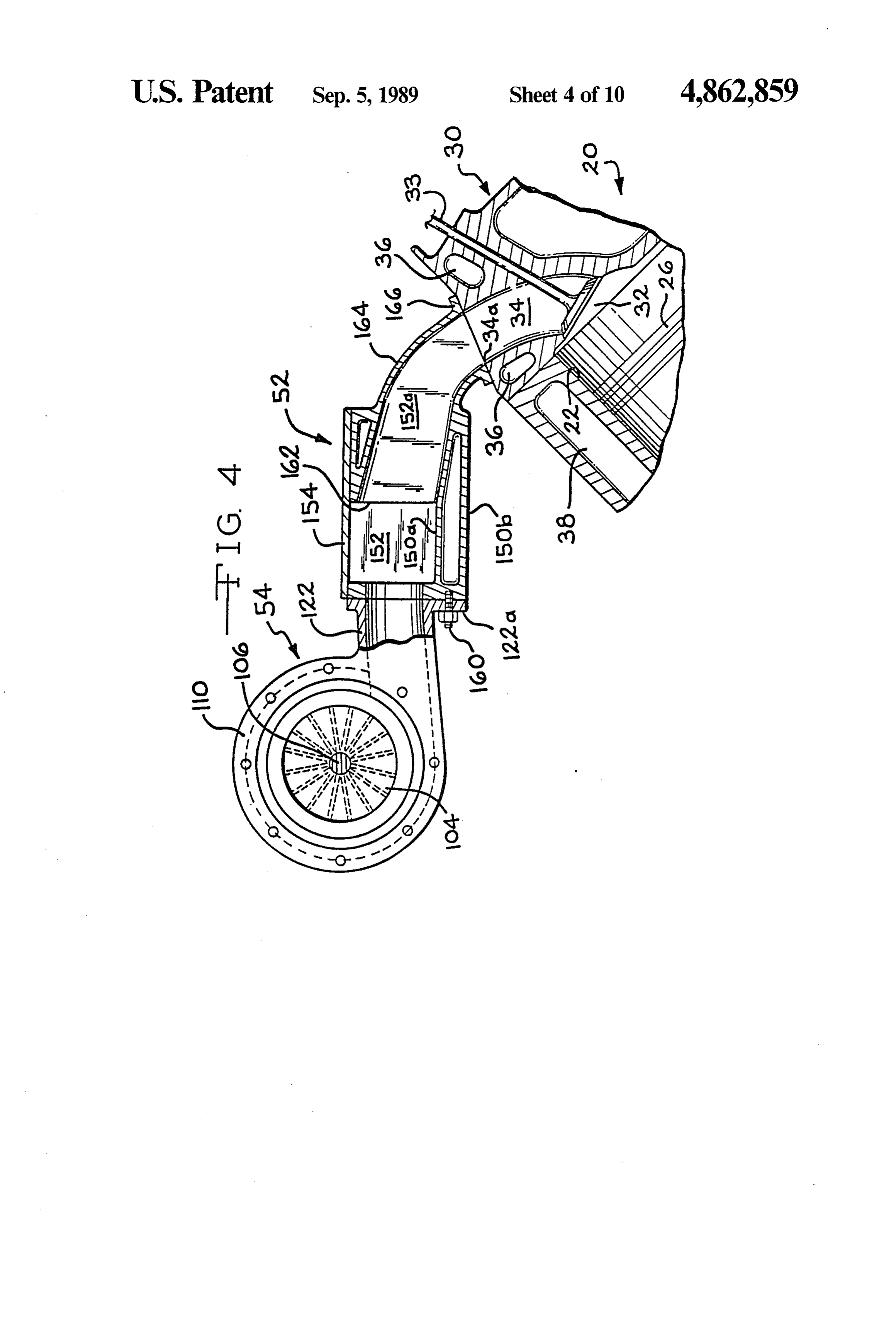
ily dissipated in driving the piston downwardly, mini mizing heat losses to the engine cooling and exhaust fuelFIG. and 1 schematically illustrates an apparatus defining exhaust flow paths constructed in accordance systems. Moreover, heat released to these engine sys 25 with the preferred tems is returned to the incoming fuel mixture via the ring also to FIGS. 3embodiment of the invention. Refer fuel vaporizing and heating devices and the homoge an internal combustion engine 20 whichis connected and 4, the apparatus in the
illus nizer. In essence, the present invention provides a "hot vapor cycle' engine in which balanced heat loops trans trated embodiment includes three cylinders 22, formed in an engine block 24, each cylinder 22 including an fer heat from the engine to the fuel mixture flow path, 30 associated piston 26. The pistons 26 are operatively the heat transferred being proportional to engine out connected to a crank shaft (an output end 28 of the put. crank shaft is shown in FIG. 3) by connecting rods in The apparatus and method disclosed by the present the conventional manner so that reciprocal movement invention has been found to substantially increase the in the pistons 26 produces rotary motion in the crank fuel efficiency and power output of a gasoline autono 35 shaft 28.
tive engine. Moreover, it was found that the low rpm A cylinder head 30 is suitably fastened to the top of torque was also increased while the tendency towards the engine block 24 and defines a combustion chamber pre-ignition and detonation were decreased. 32 in each cylinder 24 (shown in FIG. 4). A pair of cam Additional features and a full understanding can be driven poppet valves 33 (only one valve 33 is shown) obtained in reading the following detailed description controls the inflow of the fuel/air mixture into the con made in connection with the accompanying drawings. bustion chamber 32 and the outflow of combustion BRIEF DESCRIPTION OF THE DRAWINGS products. The head 30 includes integrally formed intake and exhaust passages (only the intake passage 34 is
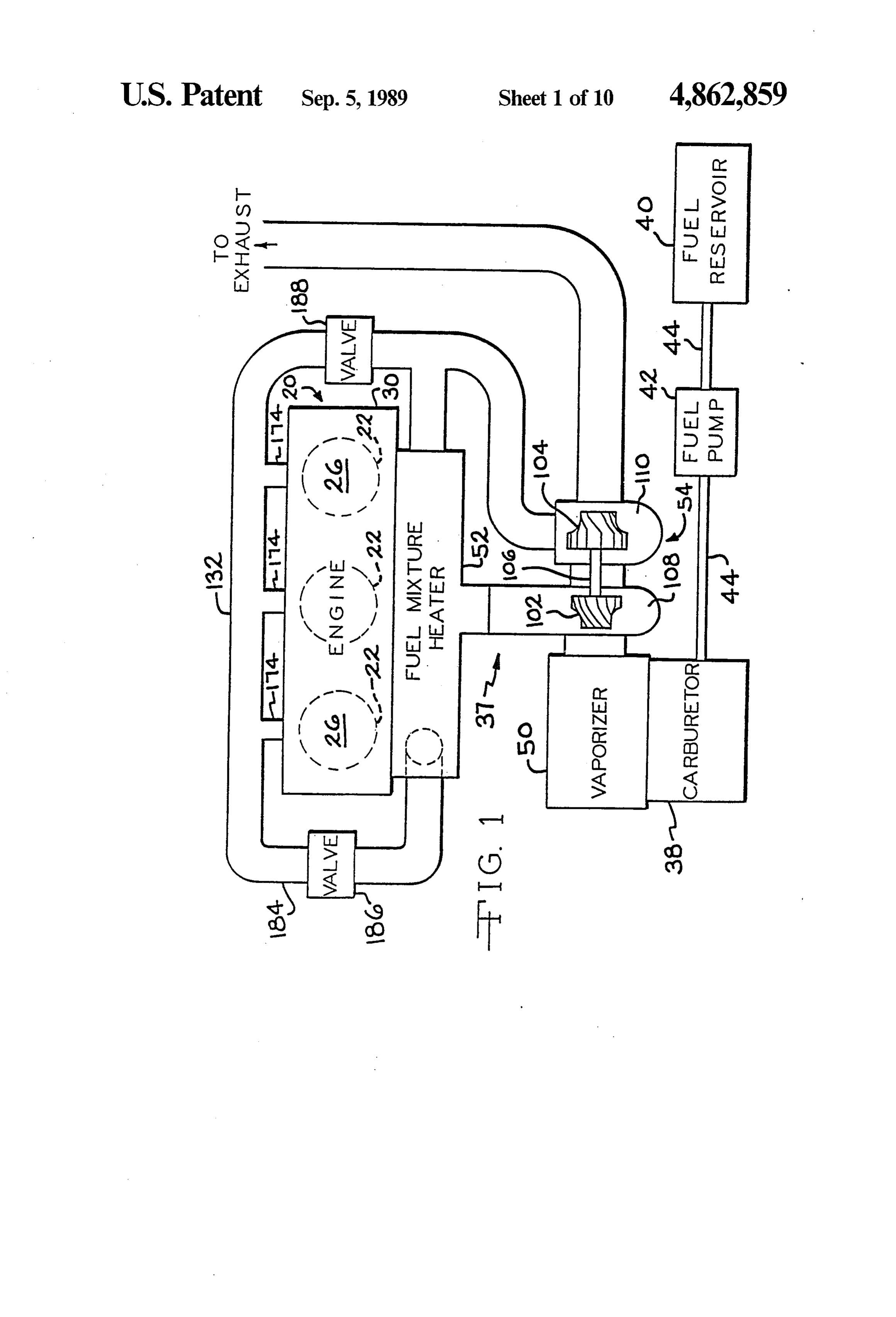
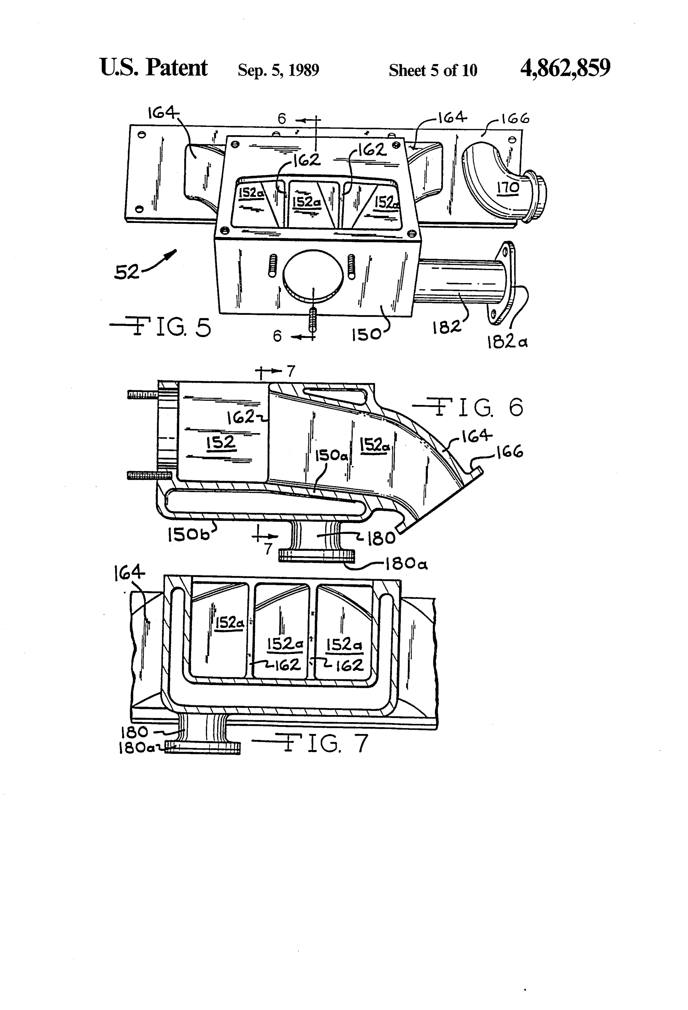
FIG. 1 is a schematic view of a fuel mixture preparing shown). The intake passages 34 extend from ports 34a and conditioning apparatus constructed in accordance 45 formed in the side of the cylinder head 30 (shown in with the preferred embodiment of the invention; FIG. 3) and the intake valves 33. Coolant passages 36 FIG. 2 is a schematic illustration of the engine cool support coolant flow through the head for removing ant circuit that provides heat to a fuel mixture vaporizer excess heat during engine operation. The coolant is constructed in accordance with the preferred embodi discharged from the cylinder head 30 through an outlet ment of the invention; SO port 36a. The cylinder block 24 also includes coolant FIG.3 is an exploded view of the fuel mixture prepar passages 38.
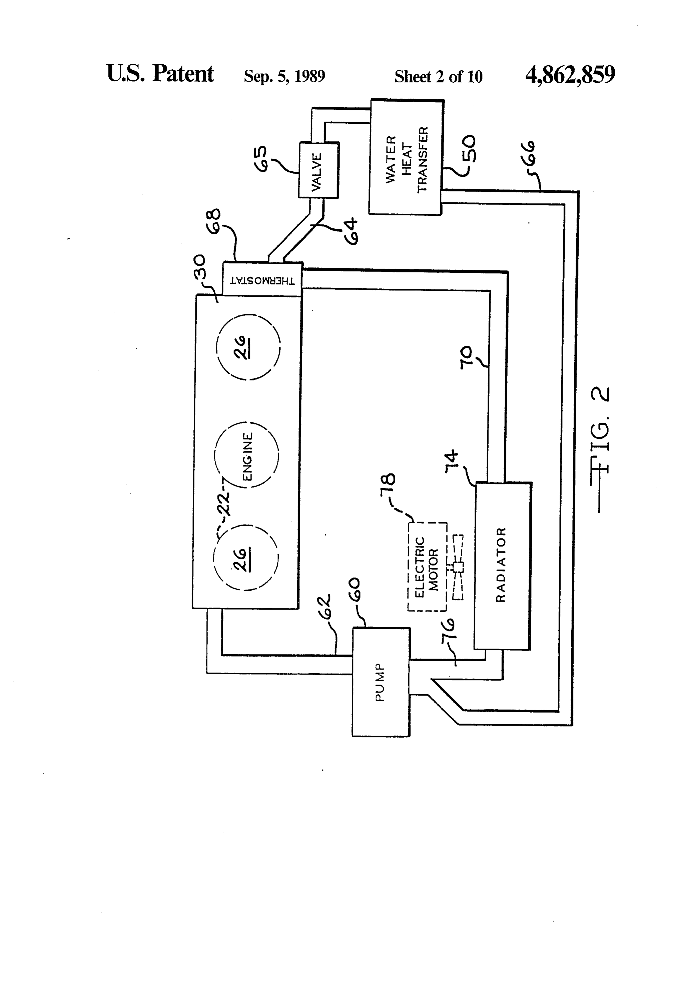
ing and conditioning apparatus; Returning to FIG. 1, the present invention provides FIG. 4 is a view partly in elevation and partly in an apparatus and structure, indicated generally by the section, of fuel mixture homogenizing and heating de reference character 37 that defines a fuel mixture flow vices constructed in accordance with the preferred 55 path extending between the cylinder intake ports 34a embodiment; and a fuel introducing device 38, preferably a carbure FIG. 5 is elevational view of the fuel mixture heater, tor. According to the invention, means for thoroughly with parts removed to show interior detail; vaporizing and mixing the fuel mixture as it travels from FIG. 6 is a cross sectional view of the fuel mixture the carburetor 38 to the engine combustion chambers 32 heater as seen along the plane indicated by the line 6-6 is provided.
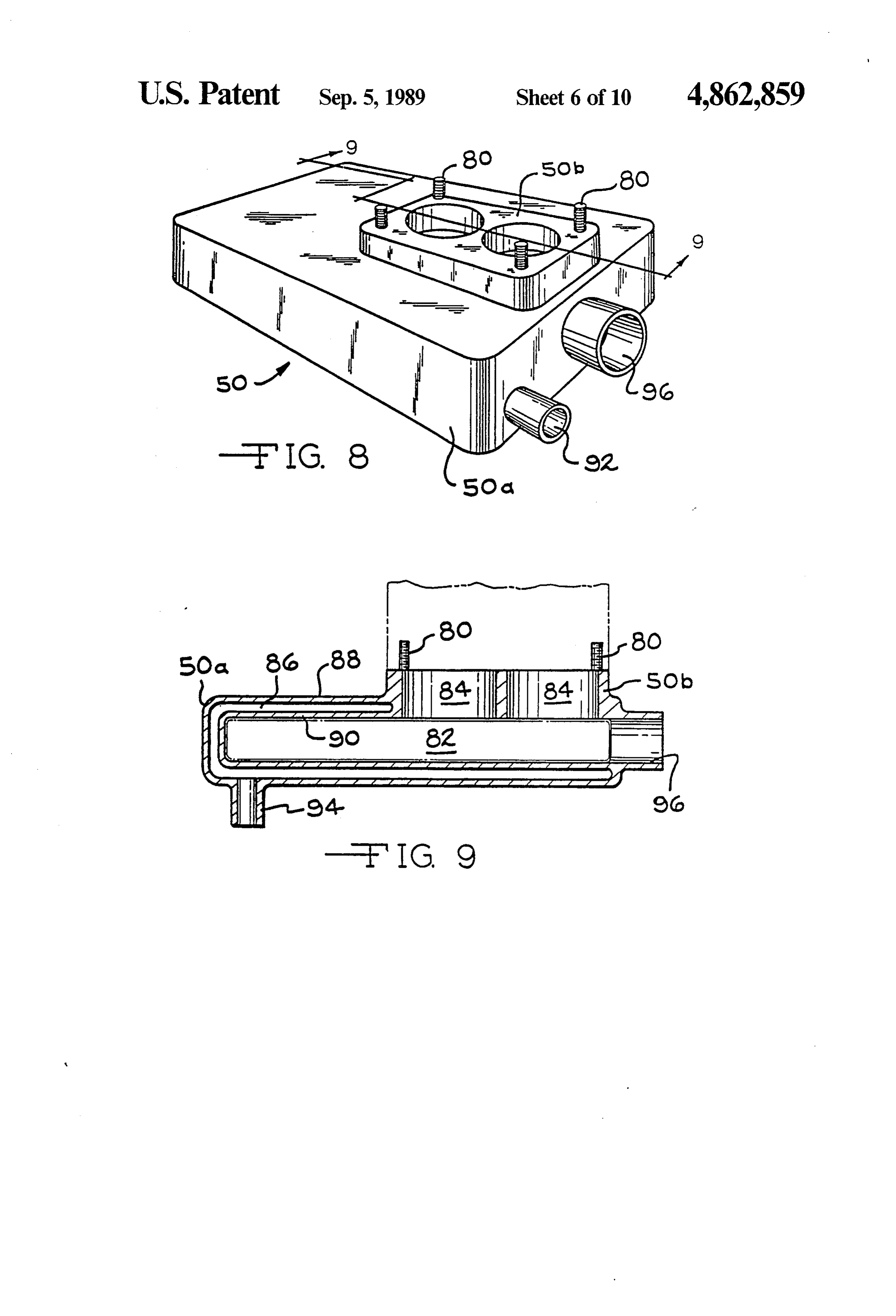
of FIG. 5; Liquid fuel is delivered to the carburetor 38 from a FIG. 7 is a sectional view of the fuel mixture heater as fuel tank 40 by a conventional fuel pump 42 and associ seen from the plane 7-7 of FIG. 6; ated conduits 44. Preferably, the carburetor 38 operates FIG. 8 is a perspective view of the vaporizer of the in a conventional manner and combines controlled engine shown schematically in FIG. 1 on an enlarged 65 amounts of air and liquid fuel to form a combustible fuel scale; mixture.
FIG. 9 is a sectional view of the vaporizer as seen In general, only a portion of the liquid fuel will be from the planes indicated by line 9-9 of FIG.8; partially vaporized in a throat of the carburetor as it
Page 16
enters the air flow stream. In accordance with the in inlet nipple 92 formed in the housing 50a and suitably vention, a fuel mixture vaporizer 50 and a fuel mixture connected to the outlet conduit 64. The coolant leaves heating device 52 are disposed in and preferably form a the vaporizer 50 through an outlet nipple 94 (shown in part of a fuel mixture flow path 37 to insure complete FIG. 9) that is suitable connected to the return conduit fuel vaporization and to heat the fuel/air mixture above 66.
the vaporization temperature of the liquid fuel, prefera The fuel mixture formed in the throat of the carbure bly to a temperature which is twice the vaporization tor 38 enters the heating chamber 82 through the pas temperature of the fuel. A fuel mixture homogenizer, sages 84. The mixture leaves the chamber 82 through a indicated generally by the reference character 54 is chamber outlet 96 formed in the housing 50a and prefer disposed in the flow path intermediate the vaporizer 50 10 ably extending in a direction orthogonal to the axes of and the heating device 52. the passages 84.
In the preferred embodiment the fuel mixture vapor Under normal engine operating conditions, it has izer 50 heats the fuel mixture with heat from the engine been found that a substantial portion of the engine heat coolant system. The invention does contemplate the use absorbed by the engine coolant is released to the fuel of exhaust heat if coolant heat is unavailable, i.e., in an 15 mixture as the mixture passes through the vaporizer 50. air-cooled engine. The engine coolant fluid loop for In effect, the coolant heat discharged to the vaporizing accomplishing this feature of the invention is illustrated fuel partially supplants the need for the coolant radiator in FIG. 2. The cooling circuit includes a conventional 74 and totally supplants the need for the cooling fan 78, water pump 60 for pumping coolant into the engine thus allowing the use of fewer and smaller components. block 24 and the cylinder head 30. The coolant is deliv 20 It has been found that the coolant flows in many ered to the engine through a supply conduit 62 and is conventional automobiles are excessive, resulting in the discharged from the head 30 into an outlet conduit 64 loss of large amounts of engine heat to the ambient. This through the coolant port 36a formed in the cylinder condition is alleviated by the present invention. Ac head 30 (shown in FIG. 3). The outlet conduit 64 has a cording to the invention, the coolant flow rate through valve 65 for adjusting the fluid flow through it. The 25 the engine is proportional to the power output of the outlet conduit 64 delivers coolant to the vaporizer 50. engine so that as the engine output increases, propor The coolant circulates through the vaporizer and is tionately more heat is carried to the fuel mixture pre subsequently discharged into a return conduit 66. The heater 50 for transfer to the incoming fuel charge. This conduit 66 communicates with the inlet side of the "heat balance' between the coolant flow rate and en pump. 30 gine output is achieved by the sizing of the coolant A thermostat housing 68 including a conventional pump 60 and the adjustment of the control valve 65. In thermostat (not shown) is provided for controlling the actual production, the valve 65 is preferably eliminated fluid communication between the conduit 64 and a radi by appropriately sizing the various coolant conduits. ator input conduit 70. As long as a coolant remains Returning to FIG. 1, the homogenizer 54 operates to below a predetermined temperature (determined by the 35 thoroughly mix the fuel mixture received from the va thermostat) the thermostat remains closed and the cool porizer 50 and insures that the fuel vapor is uniformly ant is conveyed to the input of the coolant pump 60 dispersed throughout the fuel/air mixture. Moreover, through the conduit 66. In this operating mode, the the homogenizer operates to compress the fuel air mix coolant circulation loop includes only the pump 60, the ture thereby increasing the density of the fuel charge engine block and head 24, 30 and the vaporizer 50. entering the combustion chambers 32.
Should the coolant temperature exceed the thermostat In the preferred embodiment, the homogenizer 54 setting, the thermostat will open and communicate the comprises mixing and exhaust driven turbines 102, 104 conduit 70 and the coolant will proceed through a radi fixed to a common shaft 106 and mounted for rotation ator 74 and then be returned to the cooling pump 60 by within a structure that defines separate turbine cham a radiator return conduit 76. An electrically driven fan 45 bers or housings 108, 110 associated with the turbines 78, controlled by a thermostat (not shown) is shown in 102, 104 respectively. The turbine 104 is disposed in the phantom. In tests the fan has not turned on so it prefera exhaust flow path and is in part driven by the exhaust bly is eliminated and has for this reason been shown in gases discharged by the engine 20; the rotation of the phantom. It is shown here only because it was present, turbine 104 produces attendant rotation in the turbine through inoperative, during tests in which certain data 50 102. Further rotation producing forces are supplied by was collected. the mixture flow across the mixing turbine which re The mixture vaporizer 50 preferably mounts and sults from thermal expansion, since the homogenizer is forms the support base for the carburetor 38. In accor disclosed to both homogenize and add second stage dance with this feature and as seen in FIGS. 3, 8 and 9, heat to complete and assure maintenance of a total fuel the vaporizer 50 includes a housing 50a and an inte 55 vaporization state. The rotation of the turbine 102 stirs grally formed carburetor mounted flange 50b including or homogenizes the fuel mixture passing through the vertically extending retaining studs 80. Referring in turbine housing 108 on its way to combustion chambers. particular to FIGS. 8 and 9, the housing 50a defines an Referring to FIG. 3, the originally preferred exterior interior, heating chamber 82 that communicates with construction of the homogenizer 54 is illustrated. The the throat of the carburetor through a pair of passages 60 turbine housing 108 includes an axial inlet 120 through 84that extend downwardly from the top of the carbure which the fuel mixture from the vaporizer 50 is re tor flange 50b and open into the chamber 82. ceived. The homogenized fuel mixture leaves the tur A fluid jacket 86 defined by exterior and interior bine housing 108 through a flanged nozzle outlet 122 walls 88,90 of the housing 50 surround the chamber 82. that extends tangentially from the turbine housing 108. Engine coolant is circulated in the fluid passages 86 so 65 The exhaust turbine housing 110 includes a flanged inlet that heat from the engine coolant is transferred to the 124, formed tangentially with respect to the turbine chamber 82 through the interior wall 88. The engine chamber 110. The exhaust gases passing through the coolant is communicated to the vaporizer through an housing 110 are discharged through an axial outlet com
Page 17
municating with an exhaust pipe 126. The pipe 126 vaporizer 50. When acceleration is first initiated, the includes a flange 126a clamped to an axial outlet by injected fuel immediately increases the specific density means of studs 128. The studs extend from the side of of the fuel/air mixture. This increased mixture density the exhaust turbine housing 110 and are adapted to immediately increases the pressure in the homogenizer receive suitable threaded fasteners (not shown). The 54, even though the engine RPM has not yet increased. exhaust gases discharged by engine 20 are conveyed to The homogenized fuel mixture leaves the turbine the exhaust turbine housing by an exhaust conduit 132 housing 108 and enters the fuel mixture heater 52. Re that terminates in a flange 132a. A similar flange 124a is ferring to FIGS. 3, 5, 6 and 7, the fuel mixture heater 52 mounted at the inlet 124 of the housing 110. The flanges functions somewhat as an intake manifold for the cylin 124a, 132 include a plurality of apertures 125 adapted to 10 der head 30 in that it divides and distributes the fuel receive suitable fasteners for coupling the flanges 124a, mixture to the individual cylinders 22. 132a. The turbine 104 is rotatably driven by the exhaust In the preferred embodiment, the fuel mixture heater gases travelling from the conduit 132 to the conduit 126 52 comprises an exhaust heated housing 150 that in and as discussed above, rotation of the turbine 104, in cludes spaced interior and exterior walls 150a, 150b, turn, imparts rotation to the mixture turbine 102. 15 respectively, between which are defined passages Although the homogenizer 54 bears some physical through which exhaust gases circulate to heat an inte similarity to a conventional turbocharger, which those rior chamber 152 defined by the interior wall 150a and skilled in the art will recognize as an exhaust driven a cover plate 154 (shown in FIG. 3) fastened to the top supercharger, its primary functions are the homogeniza of the housing 150 by suitable fasteners 156. The fuel tion of the fuel mixture and the addition of heat to com 20 mixture is communicated to the chamber 152 through plete, and assure maintenance of, total vaporization of an inlet aperture 158 formed in the side of the housing the fuel. Thus, while there is fuel/air mixture compres 150. A plurality of laterally extending studs 160 extend sion, as is the case with conventional turbochargers, this from the side of the housing 150 and attach the mount is not the primary function of the homogenizer. In ac ing flange 122a of the homogenizer outlet 122 to the cordance with this feature of the invention, the turbines 25 housing 150.
102, 104 are sized and selected to rotate at 2,000 to 4,000 A pair of vertically standing ribs 162 are disposed in rpm with the engine at idle and to rotate under all oper the chamber 152, a spaced distance from the aperture ating conditions. 158. The ribs 162 subdivide the mixture flow into a The boost pressure provided by the homogenizer plurality of branch flow paths 152a, each path commu under specific turbine speeds is less than the boost pres 30 nicating with one of the three combustion chambers 22. sure that would be provided by a similarly sized turbo Preferably, relatively short, individual conduits 164 charger used with a conventional internal combustion extend between the housing 150 and a mounting flange engine. The reason for the reduction in the boost pres 166 adapted to be attached to the side of the head 30, as sure realized by the present invention is due to the con seen in FIG. 3. Each conduit 164 communicates one of ditioning of the fuel mixture by the vaporizer 50. As 35 the branch flow passages 152a with one of the cylinder explained above, the vaporizer 50 adds heat to the in head intake ports 34a. A nipple 170 is also mounted to coming fuel mixture that not only vaporizes the liquid the flange 166 and communicates the coolant discharge fuel entrained in the fuel mixture, but it raises the over port 36a in the cylinder head with the conduit 64 all temperature and thus reduces the mixture density. (shown in FIG. 2).
This density reduction results in reduced boost pressure The path of exhaust gas flow to the fuel/air mixture for a given steady state turbine speed when compared heater 52 and the homogenizer 54 is shown schemati with conventional but more importantly results in in cally in FIG. 1. The exhaust conduit 132 extends into creased mixing and full vaporization of the fuel/air fluid communication with a plurality of exhaust ports mixture. This reduction in boost pressure for a given (not shown) formed in the cylinder head 30 through turbine speed is offset by the increase in turbine speed 45 three branch conduits 174, terminating in mounting which results in achieving desired boost pressures. flanges 174a. The branch conduits have elongated Although the boost pressure is somewhat self limiting straight sections adjacent the flanges to minimize back by the proper selection and sizing of the turbines 102, pressure. As seen in FIG. 3, the left end of the conduit 104, a bypass valve 140 is provided on the exhaust tur 132 is fitted with a coupling flange 176. A short nipple bine housing 110 for bypassing exhaust gas around the 50 178 and associated flange 178a extend from the side of housing in the event a malfunction is encountered that the conduit 132 about midway between the ends. As produces an excessive boost pressure. also seen in FIGS. 5 and 6, a pair of relatively short Unlike conventional turborchargers, the output pres conduits 180, 182 fitted with mounting flanges 180a, sure of the homogenizer 54 increases immediately upon 182a extend downwardly and laterally from the heater the initiation of throttle acceleration. As is known in the 55 housing 150, respectively.
art, movement of the throttle produces an immediate A conduit 184 (shown schematically in FIG. 1) com injection of fuel via an accelerating pump and/or other municates exhaust gas from the left end of the conduit acceleration enrichment devices. The addition of fuel to 132 to the conduit 180. The outlet 182 is coupled di the intake flow path does not simultaneously produce a rectly to the flange 178a of the conduit 178 extending proportionate increase in air flow through the carbure from the side of the conduit 132 and forms a return path tor. The air flow increases only upon an increase in for the exhaust gases. A pair of suitable flow control engine RPM. valves 186, 188 are disposed in the conduits 184, 132 and In conventional turborcharged engines, the output of are used to adjust the exhaust flow in the respective the turbocharger will increase only upon an increase in conduits. The valve 186 controls the amount of exhaust engine RPM which produces the necessary increased 65 gas that is communicated to the fuel mixture heater 52. exhaust flow. In the present invention, the homogenizer By properly adjusting the respective valves a heat bal 54 rotates throughout the engine operating range. As ance is obtained wherein the exhaust gas conveyed to explained above, the mixture density is reduced by the the heater 52 will deliver the requisite amount of heat to
Page 18
the fuel mixture, the heat delivered being a function of nized so that the vapor is uniformly distributed through the power output of the engine. In actual mass produc Out.
tion of the engine, the valves 186, 188 are preferably The homogenized mixture is then further heated to eliminated by suitably sizing the conduits 132, 180, 182 increase the overall temperature of the fuel mixture well and 184 to achieve the requisite flow rate of exhaust gas above the vaporization temperature of liquid fuel. Pref. through the fuel mixture heater 52. While insulation is erably, the mixture is heated to at least twice the vapori not shown for clarity, all of the exhaust gas conduits are zation temperature of the liquid fuel with the fuel air preferably insulated further to minimize heat losses. mixture reaching about 400' F. in the mixture heater Turning now to FIG.4, the profile of the fuel mixture 10 when the fuel is 93 octane unleaded gasoline. Move ment of the fuel/air mixture is important to permit mix flow path between the homogenizer 54 and the combus ture temperatures of this magnitude without reaction. tion chamber 32 is detailed. The geometry of the dis closed flow path minimizes energy losses because the Mixture velocities in the disclosed engine are such that mixture flow encounters very little path deviation. The the temperature should be kept below 440 F. to avoid reaction of the mixture in the heating chamber. It fuel mixture leaves the homogenizer 54 along a tangen 15 should tial path defined by the nozzle outlet 122 and enters the ture ofbecurrently noted that the average vaporization tempera available gasolines (at sea level) is fuel mixture heating chamber 52 along a substantially straight path. The branch flow paths 152a extend sub approximately 110 F. The heating of the fuel mixture stantially equal distances to the conduits 164 and flare not only insures complete fuel vaporization but it also adds energy to the fuel mixture that would otherwise be outwardly from the axis of the nozzle outlet flow less 20 lost than 8. The branch flow paths 152a, the conduits 164, the to the engine exhaust and cooling systems. In short, fuel/air mixture enters the combustion chambers and the cylinder head intake passages 34 define a grad with a higher energy content. Since the mixture has a ual, downwardly curving flow path that extends be higher energy content, less fuel is needed to produce the tween the chamber 152 and each combustion chamber desired temperature and pressure levels in the combus 32. In traversing this flow path, the fuel mixture sustains 25 tion chamber.
very little frictional or other energy losses. It is believed In order to achieve the optimum energy output dur that this flow path construction optimizes the combus ing combustion, the present invention also provides tion process for the mixture enters the combustion method steps for operating the engine which optimize chamber thoroughly mixed, uniformly dispersed and the combustion process. By optimizing the energy out completely vaporized. Flow through the heating cham 30 put, it has been found that the amount of waste heat ber is laminar. discharged through the engine cooling system and oth According to a feature of the invention, direct, un erwise is reduced thus contributing to the reduction in controlled heat transfer between the turbine housing radiator size and fan elimination.
108 and the vaporizer 50 is inhibited by a thermal isola According to these additional steps, the volume of tor. In particular, referring to FIG. 3, a circular flange 35 the combustion chamber is held substantially constant 200 including a plurality of apertures 202 and a centrally at or near its minimum volume during the combustion located nipple 204 is suitably fastened to the inlet 120 of process so that the gases and products of the combus the turbine chamber 108. A relatively short conduit 206 tion reaction substantially reach their maximum temper constructed from a material having a relatively low ature and pressure. The hot gases generated during this thermal conductivity is clamped to and extends be optimized combustion process are allowed to expand tween the vaporizer outlet 96 and the turbine inlet nip substantially at a constant volume at a time commenc ple 204 by suitable clamps (not shown). Preferably, the ing before there is any significant drop from the maxi conduit 206 is constructed from an elastomeric material mum temperature and pressure. In order to accomplish and provides an added feature of the invention. combustion optimization, the crank shaft stroke and Not only does the conduit 206 thermally isolate the 45 piston rod length are selected so that the piston remains vaporizer 50 from the turbine housing 108 it also pro within 0.001" of top-dead-center (TDC) for about 13 of vides vibration isolation and thereby isolates the carbu crank shaft rotation or longer.
retor 38 from engine vibration that would otherwise be The position of the wrist pin in the piston as well as transmitted from the turbine housing 108 to the vapor the piston radial clearance have been found to affect izer 50. The heat isolation provided by the conduit 206 50 piston "dwell time' at TDC. In particular, offsetting the prevents the uncontrolled heat transfer to the bowl of wrist pin position to accommodate a longer rod length the carburetor 38 that could cause fuel percolation or increases piston dwell. Increasing the piston radial vapor lock. Moreover, the vibration isolation provided clearance allows the piston to "rock' and also increases by the preferred conduit construction should reduce the piston dwell.
need for carburetor readjustment and improve the over 55 This "piston dwell' parameter is determined by di all reliability and calibration of the fuel system. rectly measuring the piston movement near TDC rela It should now be recognized that the present inven tive to crankshaft rotation, with the engine head re tion provides a method for operating an internal con moved, i.e., using a dial indicator. It will be recognized bustion engine that increases the overall efficiency of that during engine operation, the actual piston dwell at the engine by optimizing the combustion process. Ac 60 TDC may be different than measured because, with cording to the disclosed method, a controlled amount of pressure on top of the piston, relative motions of the liquid fuel, such as gasoline, is introduced into the intake moving parts may be somewhat different. However, it system of an engine and mixed with a controlled is believed the difference, if any, is not significant and it amount of air to form a combustible mixture. The air is certain that top center dwell time is increased over and entrained fuel are then heated by transferring heat 65 conventional engines. It has been found through experi from the engine coolant system, or alternately from the ence and experimentation, that sizing the piston stroke engine exhaust system to encourage the vaporization of and rod length to arrive at the dwell measurements the liquid fuel. The mixture is then stirred and homoge stated above, will produce the desired increase in com
Page 19
bustion efficiency. Using this sizing criteria and nea were used in the test. With a final drive ratio of 2.3-1, surement technique, an internal combustion engine uti the engine R.P.M. at 55 M.P.H. is 2,000. The vehicle lizing gasoline for fuel and operating at a speed range of speed was maintained within 2 mph of the posted speed between 800 and 4,000 rpm, fuel efficiency as well as limit. One hour and forty minutes of the test was spent power output is substantially increased. in city traffic and an equal amount of time was spent in Such an engine is more accurately termed an expan highway traffic. The 133 mile test loop was repeated 10 der because the piston leaves TDC when pressure is times and at the conclusion of the test it was found that essentially at its maximum so that extraction of power the vehicle averaged 48.25 miles per gallon. The dis from the working fluid is maximized due to maximiza closed performance gains in both fuel economy and tion of its expansion. It is this expansion which results in O power output were obtained without sacrificing drivea a smooth vibration free operation without counter bility.
weighting used by others to attempt to approach the It was also found that the engine was not prone to smoothness of the engine disclosed here. detonation even under high engine loads and low en An engine and fuel system embodying the present gine rpm. Moreover, the vehicle could be smoothly invention was constructed and installed in a 1980 Buick 15 accelerated in high gear, from a road speed of 20 MPH, Skylark. The vehicle weighed 3,005 lbs, two passen under both part and full throttle, without evidence of gers, full fuel accelerated 0-60 M.P.H. in 9.4 seconds. engine hesitation or flutter. The constant downshifting The mechanical parameters for the engine are listed in to maintain sufficient engine RPM often required with Table I. A measured torque curve is illustrated in FIG. conventional, small displacement engines was found to 10 and indicates a remarkably level torque output, in 20 be unnecessary.
excess of 225 ft-lbs, for an operating range of 2000-4400 rpm. Those in the art will recognize that the disclosed byItthis is believed that the apparatus and method disclosed present invention optimizes engine performance power output for a three-cylinder engine having a dis by controlling flame speed during combustion. This placement of 125 cubic inches and weighing only 320 control is achieved by the thorough preparation and lbs. in its operating mode including clutch and bell 25 mixing of the fuel mixture housing is substantially more than one would expect bustion chamber so that theprior to entry into the com mixture inducted into the from an engine this size. Moreover, it was found that chamber is homogenous and burns at a controlled rate the engine was remarkably vibration free and the radia tor with which the above identified vehicle was origi throughout the engine operating range. The heat en ergy contained in the engine coolant and exhaust sys nally equipped was reduced in size and capacity by 30 tems is utilized in the preparation process and is added about 50%.
to the fuel mixture to increase its energy output.
TABLE I This is achieved by sizing and adjusting the coolant Engine Type: 3 cyl, overhead valve and exhaust heat loops to produce a "heat balance' Displacement: 125 cu. in. 35 wherein the engine heat normally discharged to the Bore: 3.950 in. ambient (by the exhaust and coolant systems) is con Stroke: 3.4 in. veyed to the incoming fuel mixture to insure thorough Rod length: 6.5 in. mixing and vaporization. More importantly, the heat Horsepower: 240 Hip at 4000 RPM (special high per loops are critically adjusted to produce heat transfer formance fuel-test code 20 with 21 pound boost) flow rates that are proportional to the power output of Horsepower: 190 Hp at 4400 RPM (93 octane un the engine. Thus as the output increases, the amount of leaded gasoline with 10 pound boost) heat transferred to the incoming fuel mixture increases Weight: 320 lbs. proportionately. In short, an internal combustion engine Fuel economy: 48.25 MPG (combined city and high utilizing the present invention operates as a "hot vapor way) 45 cycle' engine. The apparatus disclosed, not only insures In order to achieve the earlier discussed "piston complete fuel vaporization and mixing but also heats the dwell' of 0.001" piston movement at TDC for 13 de the fuel vapor well above the vaporization temperature of grees of crankshaft rotation, the wrist pin position is fuel.
offset approximately 0.060" in the direction in which While it is believed the engine which has been de thrust is applied to the piston from the diametric center 50 scribed is, if fine tuned, fully capable of meeting present of the piston to accommodate a rod length of 6.5". and contemplated EPA regulations a test engine was Additionally, a piston radial clearance of 0.006' was constructed in which the engine which has been de selected to provide a small amount of piston "rock” scribed was fitted with mechanisms designed to provide which adds to the piston dwell. The combined effects of exhaust gas recirculation (EGR) and intake air heating. the offset and clearance permit thrust forces to offset 55 These provisions are designed primarily only to meet so the piston as the rod connected crank journal passes called “cold start' test requirements and, again, can be over dead center resulting in a closer spacing of piston eliminated by fine tuning of the engine previously de top to journal axis than in the case with conventional scribed.
construction. After the journal passes dead center the A modified homogenizer 210 is provided. The ho thrust forces are relieved and the piston centers itself. mogenizer 210 has an outer housing 212 which defines This centering action has a movement vector away an air passage 213 between the homogenizer housing from the journal and therefore it assists in maintaining 212 and an exhaust gas and turbine surrounding housing the piston near top-dead-center. 214.
A mileage test for the vehicle was conducted using a The homogenizer housing 212 includes a pair of air 133 mile driving loop that included both city and high 65 inlet passages 216. The air inlet passages 216 are posi way speeds. The vehicle drive train, i.e., transmission, tioned on opposite sides of homogenizer connection to differential gearing, etc. was standard and unmodified. the exhaust conduit 132 to entrain ambient air for heat Slightly larger diameter, commonly available, tires ing as it passes through the air passage 213.
Page 20
The homogenizer includes a heated air outlet 218 1. For use with an external ignition, internal combus which is opposite the exhaust conduit 132 so that the tion engine having at least one combustion chamber, the distance from each of the two inlets 216 to the common improvement of a hot vapor charge forming apparatus outlet 218 is equal. Air which has been warmed by the which comprises:
homogenizer passes through the outlet 218 thence 5 (a) structure defining a fuel mixture flow path be through a connected air conducting conduit 219 to a tween an air inlet and an outlet adapted to be in carburetor air intake manifold 220. The carburetor air fluid communication with a combustion chamber; intake manifold 220 has an ambient air intake 222 (b) fuel mixture introducing means disposed proxi through which unheated ambient air can pass to be mate said inlet for introducing pre-determined por delivered to the carburetor. 10 tions of air and a vaporizable fuel into said flow A temperature responsive air intake control valve 224 path;
modulates the supply of ambient air through the passage (c) the structure comprising: 222. Normally on startup the intake valve 224 remains (i) fuel mixture vaporizer means to transfer heat in a closed condition so the only air supplied to the absorbed from the engine into said fuel mixture; carburetor is air preheated by passage through the air 15 (ii) a fuel mixture homogenizer disposed in said heating passage 213. Once this air reaches that desired flow path intermediate said fuel mixture vapor temperature of about 110 F. the valve will open. If the izer and said combustion chamber, the homoge engine is operating in cool or cold climates the intake nizer being drivable by a power source to com valve will modulate to maintain intake air temperature press and mix the fuel mixture and maintain a of about 110 F. during normal operating conditions. 20 pressure differential across the homogenizer and On occasion, as an example during acceleration, air comprising means for transferring further heat to supplied through the air passage 213 and the air conduit said fuel mixture;
219 may not be adequate for operating conditions. Ac (iii) a fuel mixture heater disposed intermediate said cordingly the intake valve 224 is also vacuum sensitive fuel mixture homogenizer and the outlet of said and when engine manifold pressure drops below 4 25 fuel mixture flow path, and adapted to still fur inches the intake valve opens to allow additional ambi ther heat said homogenized fuel mixture to a ent air to be entrained into the carburetor through the point wherein only fuel in a supervaporized state intake passage 222 and the carburetor air intake mani and air is present for fluid communication into a fold 20. combustion chamber.
An EGR conduit 226 is provided, FIG. 11. This 30 2. The apparatus of claim 1 wherein the engine in EGR 226 conducts exhaust gases from the outlet side cludes a cooling system and said fuel vaporizing means of the homogenizer to the inlet side of the chamber in comprises a chamber disposed in said flow path includ which the compressor turbine 102 is located. This as ing means for transferring heat absorbed by said cooling sures that recirculated exhaust gases are thoroughly system to said fuel mixture.
admixed with the fuel air mixture supplied to the engine 35 3. The apparatus of claim 1 wherein said fuel heating and that such recirculated exhaust gases are equally means comprises a chamber disposed in said flow path distributed to each of the reaction chambers. including means for transferring heat from combustion The EGR conduit 226 is shown only schematically in gases exhausted by said combustion chamber to said FIG. 11. In practice, the connection of the EGR con fuel mixture.
duit 226 to the fuel air conducting conduit 206 or the 4. The apparatus of claim 1 wherein said fuel homog compressor turbine housing 108 is located such that enizer comprises a first turbine driven by gases ex EGR fluids are directed toward the compressor cham hausted from said combustion chamber and an associ ber. The axis of the EGR inlet is at an angle of less than ated turbine chamber, said homogenizer including a 45 with the axis of the fuel air conduit 206 and the two second turbine in driven engagement with said first axes are located in a common plane which includes the 45 turbine, rotatable in the mixture flow path and operative axis of the turbine 102. to both homogenize and compress the fuel mixture. The configuration of the compressor turbine housing 5. The apparatus of claim 1 wherein the internal com and its mating with the compressor turbine is best illus bustion engine includes a plurality of combustion cham trated in FIG. 11. The housing 108 includes an outlet bers and said fuel mixture heating means subdivides the opening 208 in a portion of the housing which fits 50 fuel mixture flow into a plurality of branch flow paths, closely with the compressor turbine 102. The outlet each branch communicating with one of said combus provides a constricting orifice for assisting in isolating tion chambers.
the vaporizer 50 from low manifold pressure. In the test 6. The apparatus of claim 2 wherein said fuel vaporiz engine used to produce the test data presented previ ing means is sized to exchange enough heat to said fuel ously, the compressor turbine was 2.2 inches in diame 55 mixture to maintain said fluid coolant below a predeter ter. The outlet 208 was one inch in diameter and was mined operating temperature.
followed downstream by housing walls of a frusto coni 7. The apparatus of claim 1 wherein said fuel mixture cal shaped contour. These housing walls flare from the introducing means comprises a carburetor. one inch outlet opening 208 to a two inch diameter in an 8. Method for operating an internal ignition, internal axial length of one inch. Thereafter the outer side walls 60 combustion engine having at least one combustion of the two outer flow paths 152a flare outwardly at 8 chamber, a fluid coolant system and exhaust system or less within the interior of fuel mixture heater 152. adapted to discharge combustion gases from a combus Although the invention has been described with a tion chamber, comprising the steps of:
certain degree of particularity, it is understood that (a) providing a fuel mixture flow path extending be various changes can be made to it by those skilled in the 65 tween an air inlet and an outlet that is in fluid com art without departing from the spirit or scope of the munication with a combustion chamber; invention as described and hereinafter claimed. (b) introducing air and a vaporizable fluid into said I claim: flow path proximate said inlet to form a combusti
Page 21
ble fuel mixture, said fuel having a given average gases which comprise oxygen and are adapted to vaporization temperature at sea level; react with said fuel for combustion; (c) preheating said fuel mixture by transferring heat (b) initially heating the entrained fuel with heat en from engine coolant fluid which is at a temperature ergy derived from said engine as said fuel and in excess of said average vaporization temperature, 5 gases flow along a constrained path; thereby initially to vaporize said fuel towards the (c) admixing and further heating said pre-heated fuel vapor state; and gasses to produce a substantially homogenous (d) homogenizing and further heating said pre-heated mixture of vaporized fuel and gases while apply fuel mixture while urging said further heated fuel 10 ing a pressure differential to inhibit reverse flow of mixture towards said combustion chamber by a said mixture through a pumping means driven by pumping means driven by an external power an external power source;
Source;
(d) thereafter still further heating the mixture with (e) still further heating said pre-heated and homoge heat energy derived from the engine so that the nized fuel mixture to a temperature well in excess 15 resulting mixture will be at a temperature well in of said average vaporization temperature by trans excess of said vaporization temperature of the fuels, ferring heat from said exhaust system into said fuel thereby to create a mixture of gases and fuel vapor in a supervaporized state; and mixture, thereby creating a supervaporized, pres (e) introducing said supervaporized vapor and gas surized fuel vapor state; and mixture into a combustion chamber, whereby all (f) admitting said supervaporized vapor mixture into 20 fuel fractions introduced into said engine are ho a combustion chamber at pre-determined intervals. mogenized and in the vapor state. 9. A method of providing a vaporized fuel and gas 10. The method of claim 9 wherein at least some of mixture for use in an internal combustion engine, com the heat energy is derived from engine exhaust gases. prising the steps of: 11. The method of claim 9 wherein at least some of (a) entraining a vaporizable fuel having a given va- 25 the heat is derived from engineck coolant. porization temperature at sea level into a flow of sk k :
Provenance
- Collection
- Cited prior art
- Original PDF
- patentimages.storage.googleapis.com →
- Filed
- 1988-03-02
- Pages
- 21
- Method
- pdftotext (the PDF's own text layer) + pdftoppm 300dpi page scans
- Source
- Google Patents bibliographic record
- Granted
- 1989-09-05
- Inventors
- Henry Yunick
- Transcribed from
- patentimages.storage.googleapis.com →