patent · US5718819
Process and electrolyzer for the electrolysis of a fluid electrolyte
17 February 1998
Page 1 — bibliographic record
United States Patent 19 11 Patent Number: 5,718,819 Peschka et al. 45 Date of Patent: Feb. 17, 1998
54 PROCESS AND ELECTROLYZER FOR THE 27 33 444 2/1979 Germany. ELECTROLYSS OF A FLUD 28 19739 11/1979 Germany.
ELECTROLYTE 28 19740 1 1/1979 Germany.
75) Inventors: Walter Peschka, Sindelfingen; 36 18 119A1 12/1987 Germany. Gottfried Schneider, Stuttgart, both of 2001675 2/1979 United Kingdom .
Germany 73) Assignee: Deutsche Forschungsanstalt fuer Primary Examiner-Arun S. Phasge Luft- und Raumfahrt e.V., Bonn, Attorney, Agent, or Firm-Barry R. Lipsitz
Germany 57 ABSTRACT 21 Appl. No.: 600,679 In order to improve a process for the electrolysis of a fluid 22 Filed: Feb. 13, 1996 electrolyte containing cations and anions in an electrolytic 30 Foreign Application Priority Data cell with a cathode and an anode located opposite the cathode such that primary energy not present in an electrical
Feb. 13, 1995 DEl Germany ........................ 19504 632.3 form, in particular thermal energy from reservoirs having a (51) Int. Cl. ............ C02F 1/46; B01D 17/06 moderately high temperature, can be used for the electrolysis 52 U.S. Cl. .......................... 205/339; 205/628; 205/637; with lower losses, it is suggested that a current path between 205/745; 204/155; 204/660; 204/666; 204/672; the cathode and the anode be closed, that a magnetic field be 204/673; 204/DIG. 5 applied to the electrolytic cell and that a relative movement (58) Field of Search .................................... 205/339, 628, between the magnetic field and the electrolyte be generated 205/637, 745; 204/155, 660, 666, 672, so that on account of the effect of Lorentz forces the cations 673, DIG. 5 migrate to the cathode and the anions to the anode and products of electrolysis beformed on the cathode and on the (56 References Cited anode in electrolytic reactions, wherein the charge equal
by the current path closed between the cathode and the 4,747,925 5/1988 Hasebe et al. ..................... 204/DIG. 5 anode.
FOREIGN PATENT DOCUMENTS
2 39819 2/1979 France. 37 Claims, 5 Drawing Sheets
Page 2
Drawing sheet — no readable text.
Page 3
Drawing sheet — no readable text.
Page 4
Drawing sheet — no readable text.
Page 5
Drawing sheet — no readable text.
Page 6
Drawing sheet — no readable text.
Page 7
PROCESS AND ELECTROLYZER FOR THE erated in a simple manner, and a stationary device for ELECTROLYSIS OF A FLUID generating a magnetic field is easier to construct than a ELECTROLYTE movable one and is subject to wear and tear to a lesser extet.
The present invention relates to a process for the elec 5 It is particularly favorable when the flow rate of the trolysis of a fluid electrolyte containing cations and anions electrolyte relative to the magnetic field is at least 20 m/s and in an electrolytic cell with a cathode and an anode located the component of the magnetic field at right angles to the opposite the cathode. flow rate of the electrolyte is at least two Tesla. The Lorentz A large number of processes for electrolysis of this type forces acting at such a flow rate of the electrolyte and with are known. 10 such a magnetic field allow the electrolysis to be carried out In the known processes for electrolysis, an electrical field in electrolytic cells with compact dimensions, is generated between the cathode and the anode by means of The magnetic field is advantageously generated by super an external voltage source. In this electrical field, the cations conducting coils. With coils of this type it is also possible to migrate to the cathode and the anions to the anode due to the maintain high magnetic fields in an economic manner since effect of electrostatic forces. The energy to be used for the 15 no additional losses of ohmic resistances occur. electrolysis of the electrolyte is thereby taken from the In addition, it is of advantage when a liquid is used as electrical field and must, therefore, be available in the form electrolyte. In the liquid state, the ion densities are greater of electrical energy. than in the gaseous state and so a larger quantity of products Normally, the energy available is not, however, primarily of electrolysis can be formed per unit of time. present in the form of electrical energy but, for example, in It is particularly advantageous when such a high pressure the form of thermal energy. For use in the conventional is generated in the electrolytic cell and/or such a flow rate of processes for electrolysis, the primary energy must then be the electrolyte relative to the electrodes that the products of converted first of all into electrical energy which, as is well electrolysis essentially do not mix with one another. In this known, entails significant losses in energy. The use, in case, a diaphragm in the electrolytic cell, which would particular, of thermal energy from heat reservoirs with 25 represent an additional resistance for the electrolyte flow temperatures in the moderately high range (approximately and, in addition, limit the useful life of the electrolytic cell, 200° to 400° C.) thus becomes unprofitable. can be omitted.
The object underlying the invention was therefore to The turnover in products of electrolysis may be increased improve an inventive process for the electrolysis of a fluid in a simple manner when several electrolytic cells each electrolyte such that primary energy not present in an 30 advantageously have a branch flow of the electrolyte flowing electrical form, in particular thermal energy from reservoirs through them. By closing inlet openings of individual elec having a moderately high temperature, can be used for the trolytic cells, it is possible to adjust the quantity of products electrolysis with lower losses. of electrolysis resulting per unit of time to the requirements. This object is accomplished in accordance with the It is favorable when the electrolyte is conveyed in a invention, in a process for electrolysis of the type described 35 circuit. This means that the kinetic energy contained in the at the outset, in that a current path between the cathode and electrolyte flow can be utilized in an optimum manner. the anode is closed, that a magnetic field is applied to the No details have so far been given concerning the type of electrolytic cell and that a relative movement between the generation of the electrolyte flow.
magnetic field and the electrolyte is generated so that on The flow of the electrolyte can be generated in a simple account of the effect of Lorentz forces the cations migrate to manner with the aid of a mechanical pump which is driven the cathode and the anions to the anode and products of by a thermal engine or by water power depending on the electrolysis are formed on the cathode and on the anode in type of primary energy available.
electrolytic reactions, wherein the charge equalization nec It can also be advantageously provided for the flow of the essary for the electrolytic reactions is carried out by the electrolyte to be generated with the aid of a magnetohydro current path closed between the cathode and the anode. 45 dynamic pump. Such a pump does not contain any movable With the inventive concept it is possible to omit an components which would be subject to heavy wear and tear. external electrical field. It is, therefore, no longer necessary As a magnetohydrodynamic pump is driven with elec to convert the primary energy into electrical energy, and the trical energy, it is preferably used in addition to a pump losses connected with this conversion are avoided. driven by a different type of energy in order to replace the Moreover, the amount of apparatus required is reduced 50 latter during any failure.
since no generator or other source of electrical energy is It is particularly advantageous to generate the flow of the necessary to carry out the inventive process. electrolyte with the aid of a steamjet injector. The steamjet The migration of the cations to the cathode and of the can be generated by evaporating a liquid by adding heat anions to the anode is brought about by Lorentz forces in the from a heat reservoir with a moderately high temperature. magnetic field which, itself, does not carry out any work on 55 In this respect, it is favorable when the injected steam is the anions or cations and from which no energy is, therefore, generated by partially evaporating the electrolyte. In this removed for the electrolysis. case, the substance introduced into the electrolyte with the Rather, the energy required is taken directly from the aid of a steamjet injector is withdrawn from the electrolyte kinetic energy of the relative movement between the mag by evaporation prior to or following the injection so that, netic field and the electrolyte. altogether, the composition of the electrolyte remains The relative movement between the magnetic field and unchanged.
the electrolyte can, in principle, consist in any optional If an aqueous solution is used as electrolyte, this has the manner of movements of the magnetic field and the elec advantage that the solvent water can already be evaporated at moderately high temperatures at atmospheric pressure.
trolyte.
It is, however, of advantage when the magnetic field is 65 It is particularly advantageous to use an azeotropic stationary and the electrolyte is moved relative to the mixture as electrolyte since, in this case, the percentage magnetic field. A flow of the fluid electrolyte can be gen composition of the electrolyte during evaporation is main
Page 8
tained and no electrolytic brine, which could, in certain products of electrolysis are formed on the cathode and the circumstances, be chemically aggressive, is formed. anode in electrolytic reactions, wherein the charge equal It is favorable when the heat required for generating the ization necessary for the electrolytic reactions is carried out injected steam is taken from a heated working medium, for by the current path closed between the cathode and the example steam or compressed water, of a conventional or 5 anode.
nuclear thermal power station. During a weakload period of The inventive electrolyzer therefore offers the advantage such a power station the heated working medium can be that an external electrical field for separating the cations and branched off instead of, as usual, being supplied to turbines anions of the electrolyte can be dispensed with. Thus, non-electrical sources of primary energy can be used for the of the power station and then conveyed through a heat operation of the electrolyzer without any conversion into exchanger in order to evaporate the liquid to be evaporated, electrical energy being necessary beforehand, which would for example the electrolyte, and drive the steamjet injector entail additional apparatus and losses in energy. with the steam thus generated. In this way, it is possible to The required relative movement between the magnetic avoid, for example, running down the steam generators of field and the electrolyte can, in principle, consist of a the thermal power station during weak load periods, which movement of the magnetic field and a movement of the is of considerable advantage, in particular, for nuclear power 15 electrolyte.
stations. As a rule, it is, however, favorable to leave the device for It is also favorable when the heatrequired for generating generating the magnetic field stationary and, instead, pro the injected steam is obtained from solar energy or geother vide a device for generating an electrolyte flow, mally. Both sources of energy allow heat to be made The electrolyzer advantageously has at least one super available at a moderately high temperature level, which is 20 conducting magnetic coil. Superconducting magnetic coils sufficient for generating steam, in particular, from aqueous allow the magnetic field required for generating the Lorentz solutions, in a manner which is economic and conserves the forces to be maintained over a long period of time more or environment. less without loss.
Particularly when using solar energy, it is advantageous It is favorable when the electrolytic cell of the electro to store the heat required for the steam generation tempo 25 lyzer is filled with a liquid electrolyte. On account of the rarily in a heat storage unit. As a result of this measure, it is distinctly higher ion density in a liquid electrolyte in com possible to carry out the steam generation and, therefore, the parison with a gaseous electrolyte, a greater quantity of inventive process for electrolysis continuously and indepen products of electrolysis can be obtained per unit of time from dently of the momentary solar radiation. a liquid electrolyte.
If the flow of the electrolyte is generated with the aid of 30 It likewise serves to increase the production rate of a steamjetinjector, it is, furthermore, of advantage when the products of electrolysis when the electrolyzer has several electrolyte is cooled prior to the injection of the steam such electrolytic cells.
that the injected steam condenses essentially completely in These electrolytic cells can, for example, be arranged the electrolyte. As a result of this, it is ensured that the linearly next to one another in order to be able to keep the impulse of the steam is transferred to the electrolyte as 35 conductive connections between the anode of one electro completely as possible, and the formation of gas bubbles in lytic cell and the cathode of the electrolytic cell adjacent to the electrolyte, which could reduce the effectiveness of the this electrolytic cell short. A longer, conductive connection process for electrolysis and, in certain circumstances, dam is required only between the outwardly situated electrodes of age the devices used for the process, is prevented. the two electrolytic cells located at the ends of the linear In a preferred embodiment of the inventive process, the arrangement.
energy stored in the magnetic field is, moreover, used in the Such a longer conductive connection can be dispensed case of electrolyzers of adequate size for the peak load with when the electrolytic cells are favorably arranged in the service in electrical networks. shape of a closed ring. In this case, two additional electro The inventive process for electrolysis described in the lytic cells are adjacent to each of the electrolytic cells. above is particularly suitable for use in the production of 45 Furthermore, the forces transferred from an electrolyte flow hydrogen by means of electrolytic dissociation of water. to the ring-shaped arrangement consisting of electrolytic Such use exploits the advantages of the inventive process in cells cancel each other when the electrolytic cells have the an optimum manner and enables primary energy in a non electrolyte flowing through them in the same direction (i.e., electrical form, in particular thermal energy from heat for example, from the inner side of the ring-shaped arrange reservoirs having a moderately high temperature, to be SO ment to its outer side).
converted into a form which is easy to store and transport In each arrangement of electrolytic cells, in which two with a high degree of efficiency in comparison with con electrolytic cells are adjacent one another each time, it is of ventional processes. advantage when these electrolytic cells have bipolar elec Furthermore, the object described at the outset is also trodes which serve not only as anode of the one electrolytic accomplished in accordance with the invention, by an elec 55 cell but also as cathode of the other electrolytic cell. As a trolyzer for the electrolysis of a fluid electrolyte which has result, a considerable saving in material is possible, an electrolytic cell with a cathode and an anode located If the electrolyzer has a device for generating an elec opposite the cathode, in that the electrolyzer has a conduc trolyte flow, it is, furthermore, of advantage when the tive connection between the cathode and the anode, a device electrolyzer has an electrolyte circuit with an electrolyte for generating a magnetic field penetrating the electrolytic return line. Due to this it is possible to supply new electro cell and a device for generating a relative movement lyte continuously to the electrolyzer and to electrolyze this between the magnetic field and the electrolyte. completely during several passages through the electrolytic In the inventive electrolyzer, Lorentz forces, which act cell.
on the cations and the anions of the electrolyte due to the No details have so far been given in respect of the device relative movement between the magnetic field and the 65 for generating an electrolyte flow.
electrolyte, are generated and these see to it that the cations In principle, all devices provided for generating a fluid migrate to the cathode and the anions to the anode and flow can be used.
Page 9
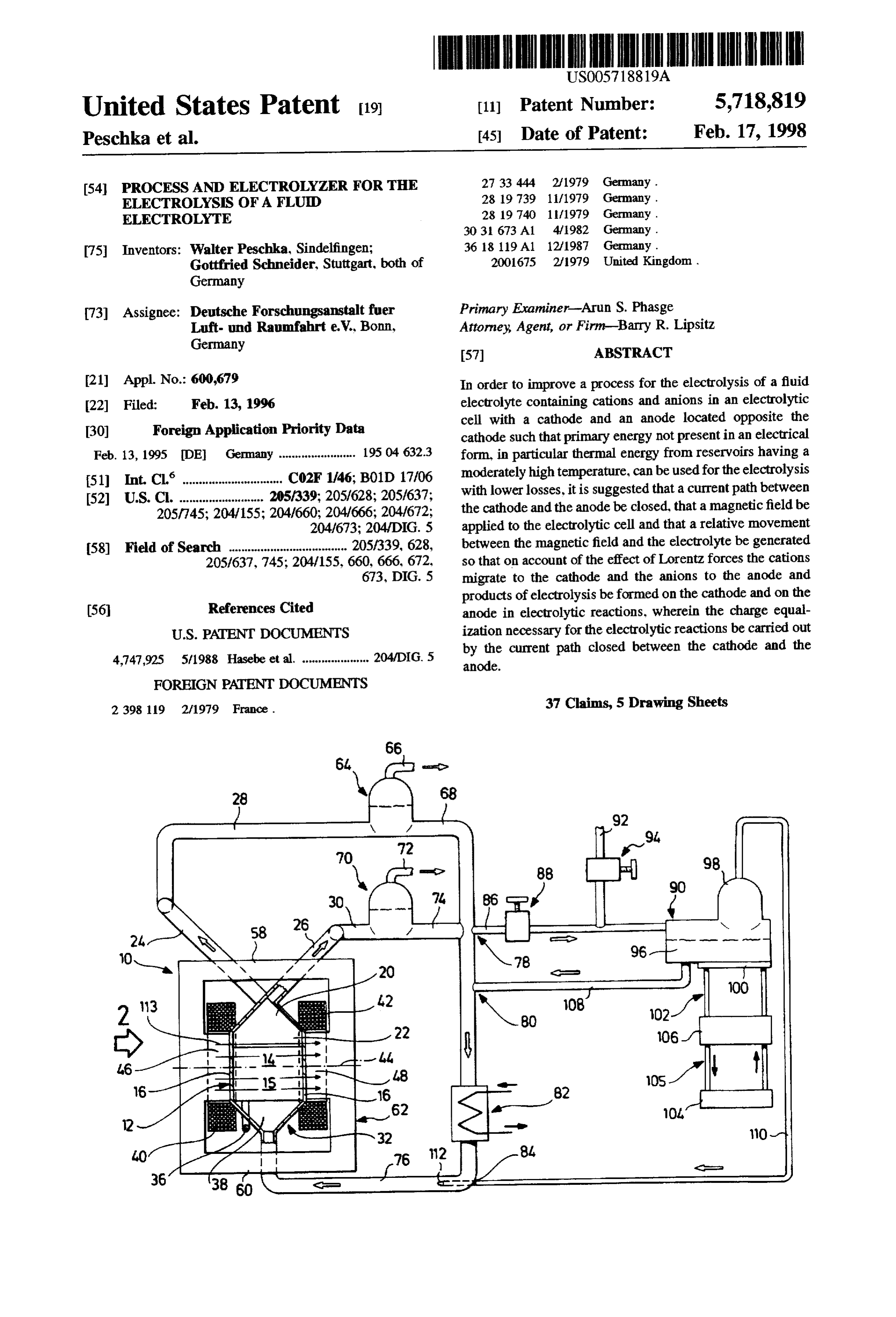
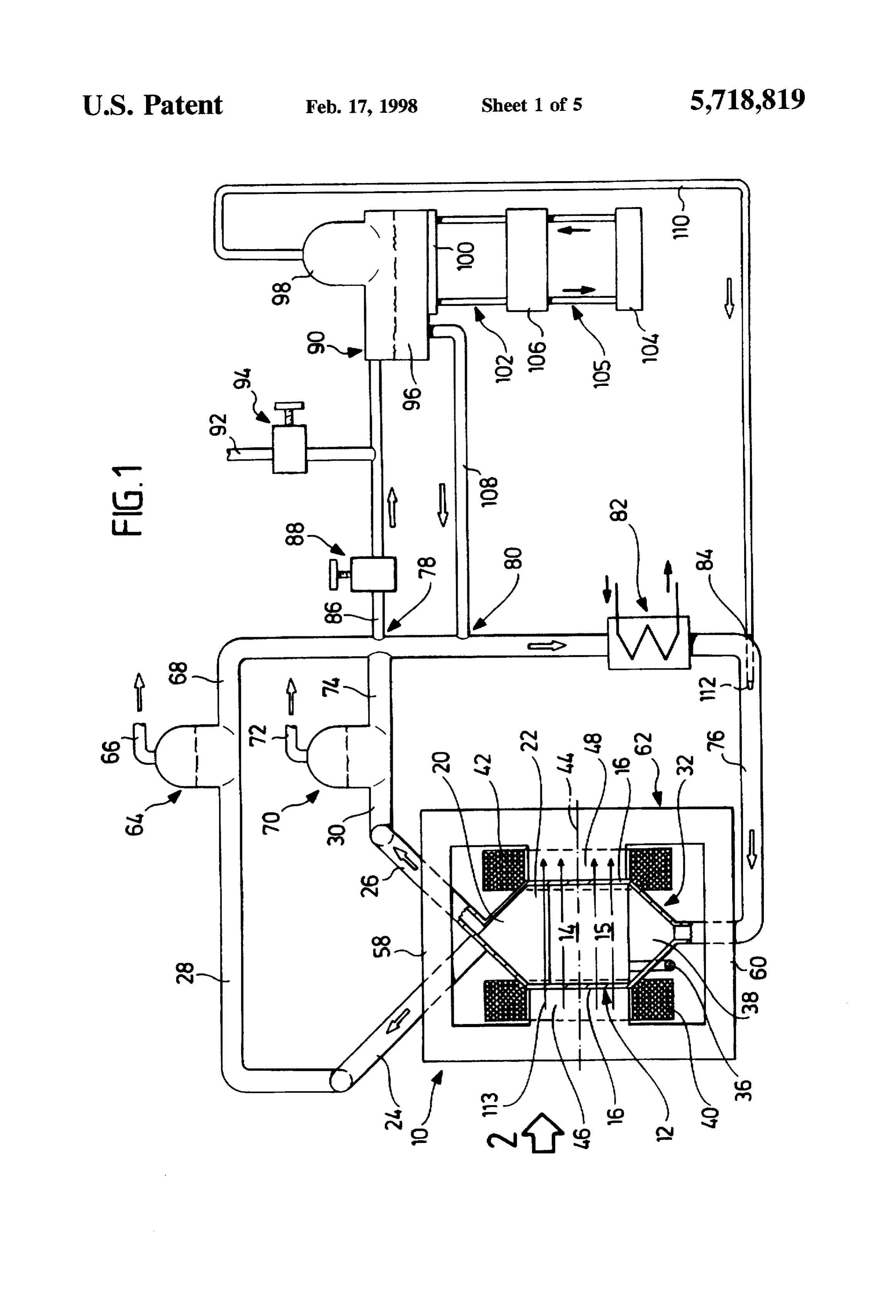
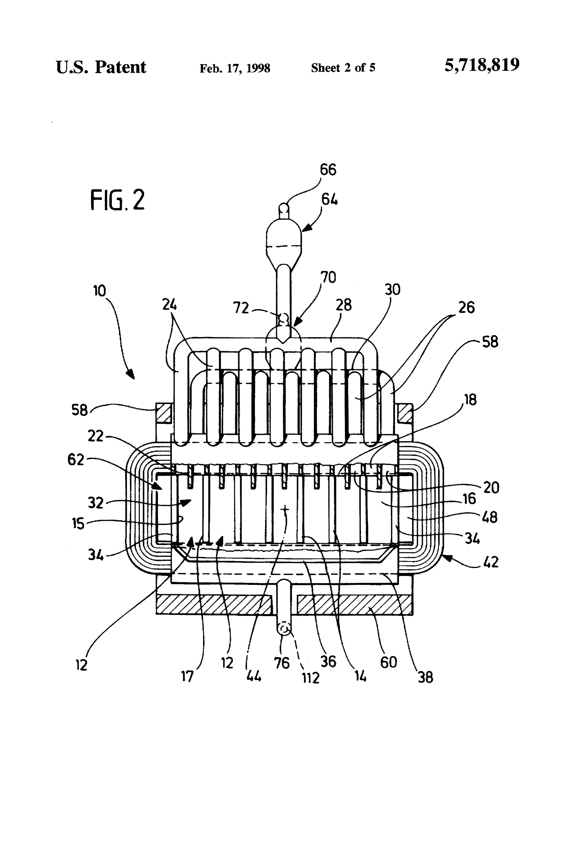
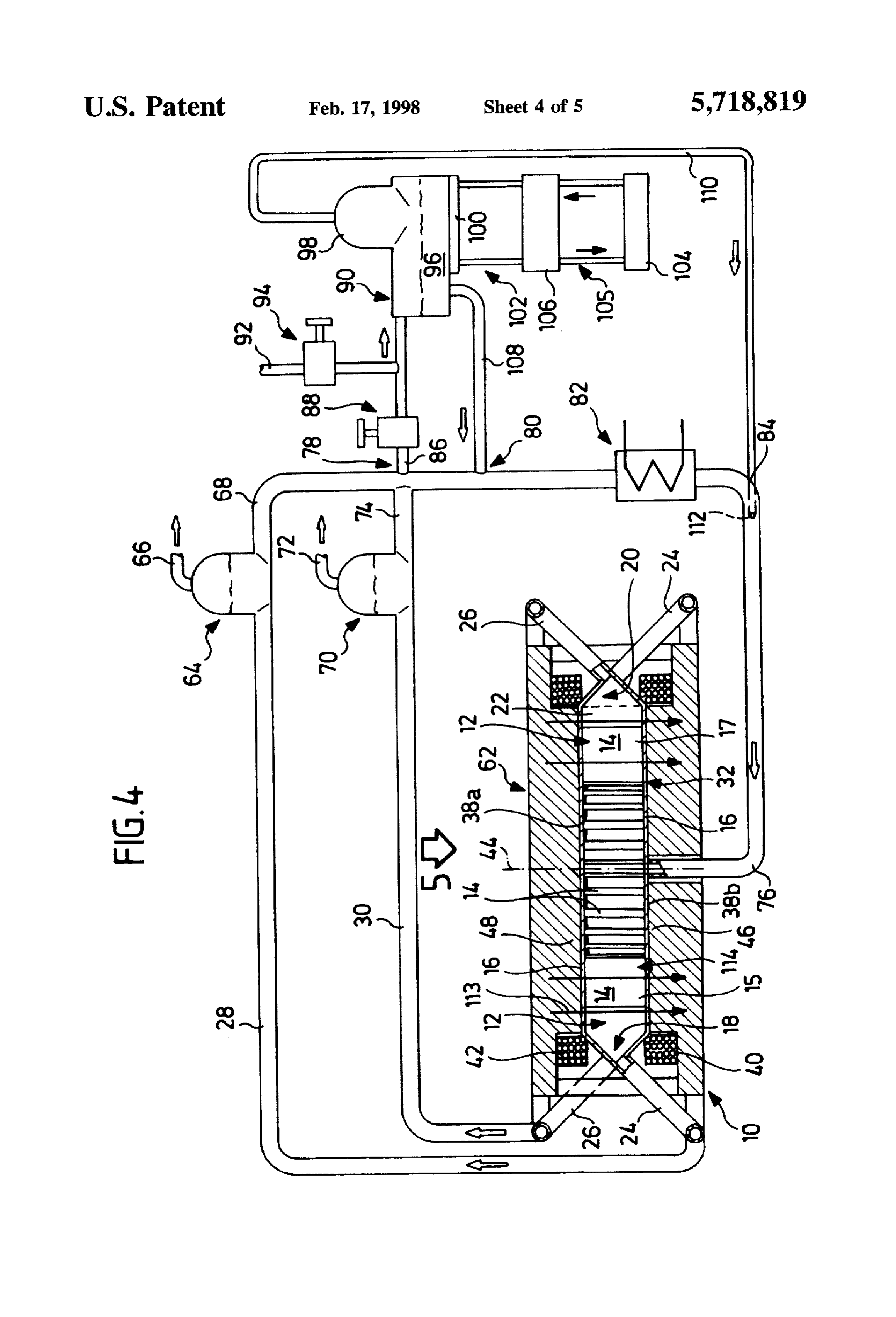
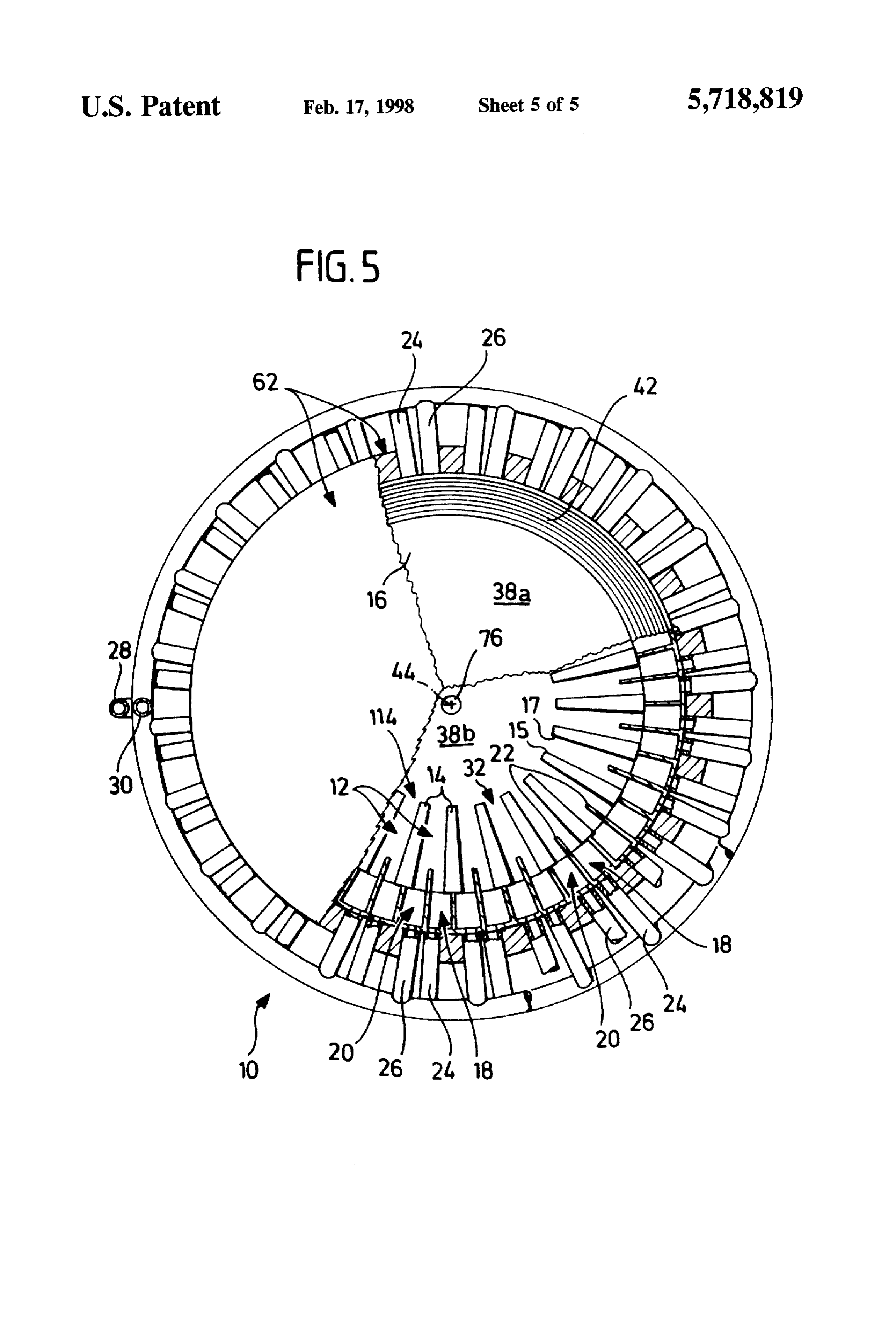
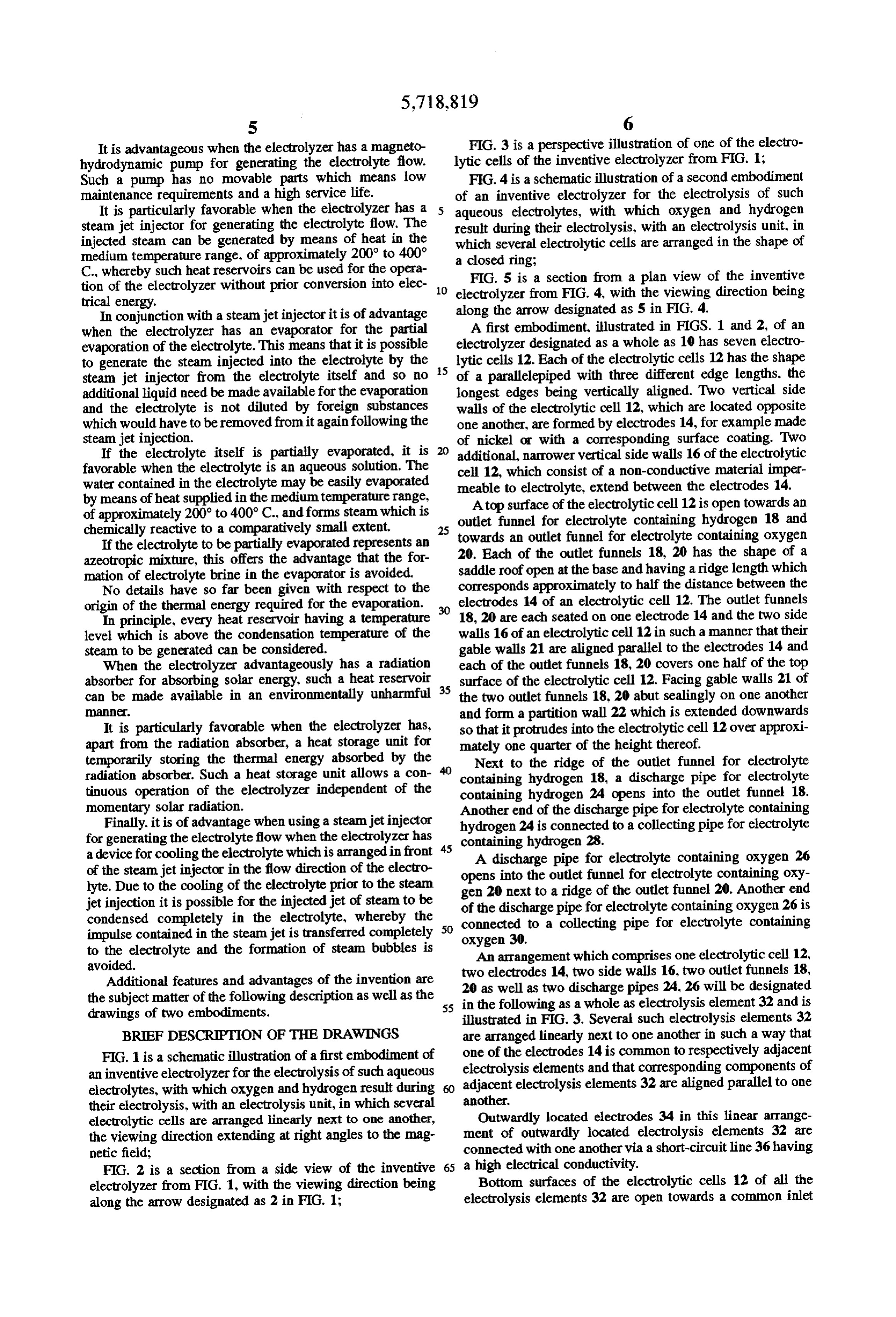
It is advantageous when the electrolyzer has a magneto FIG. 3 is a perspective illustration of one of the electro hydrodynamic pump for generating the electrolyte flow. lytic cells of the inventive electrolyzer from FIG. 1; Such a pump has no movable parts which means low FIG. 4 is a schematic illustration of a second embodiment maintenance requirements and a high service life. of an inventive electrolyzer for the electrolysis of such It is particularly favorable when the electrolyzer has a aqueous electrolytes, with which oxygen and hydrogen steam jet injector for generating the electrolyte flow. The result during their electrolysis, with an electrolysis unit, in injected steam can be generated by means of heat in the which several electrolytic cells are arranged in the shape of medium temperature range, of approximately 200 to 400°
C., whereby such heat reservoirs can be used for the opera a closed ring;
tion of the electrolyzer without prior conversion into elec 10 electrolyzeris from
FIG. 5 a section from a plan view of the inventive
FIG. 4, with the viewing direction being trical energy.
In conjunction with a steamjet injector it is of advantage along the arrow designated as 5 in FIG. 4. when the electrolyzer has an evaporator for the partial A first embodiment, illustrated in FIGS. 1 and 2, of an evaporation of the electrolyte. This means that it is possible electrolyzer designated as a whole as 10 has seven electro to generate the steam injected into the electrolyte by the 15 lytic cells 12. Each of the electrolytic cells 12 has the shape steam jet injector from the electrolyte itself and so no of a parallelepiped with three different edge lengths, the additional liquid need be made available for the evaporation longest edges being vertically aligned. Two vertical side and the electrolyte is not diluted by foreign substances walls of the electrolytic cell 12, which are located opposite which would have to be removed fromit again following the one another, are formed by electrodes 14, for example made steam jet injection. of nickel or with a corresponding surface coating. Two If the electrolyte itself is partially evaporated, it is additional, narrower vertical side walls 16 of the electrolytic favorable when the electrolyte is an aqueous solution. The cell 12, which consist of a non-conductive material imper water contained in the electrolyte may be easily evaporated meable to electrolyte, extend between the electrodes 14. by means of heat supplied in the medium temperature range, Atop surface of the electrolytic cell 12 is open towards an of approximately 200 to 400° C., and forms steam which is outlet funnel for electrolyte containing hydrogen 18 and chemically reactive to a comparatively small extent. 25 towards an outlet funnel for electrolyte containing oxygen
If the electrolyte to be partially evaporated represents an 20. Each of the outlet funnels 18, 20 has the shape of a azeotropic mixture, this offers the advantage that the for saddle roof open at the base and having a ridge length which mation of electrolyte brine in the evaporator is avoided.
No details have so far been given with respect to the corresponds approximately to half the distance between the origin of the thermal energy required for the evaporation. electrodes 14 of an electrolytic cell 12. The outlet funnels In principle, every heat reservoir having a temperature 18, 20 are each seated on one electrode 14 and the two side level which is above the condensation temperature of the walls 16 of an electrolytic cell 12 in such a manner that their steam to be generated can be considered. gable walls 21 are aligned parallel to the electrodes 14 and When the electrolyzer advantageously has a radiation each of the outlet funnels 18, 20 covers one half of the top absorber for absorbing solar energy, such a heat reservoir 35 surface of the electrolytic cell 12. Facing gable walls 21 of can be made available in an environmentally unharmful the two outlet funnels 18, 20 abut sealingly on one another 2. and form a partition wall 22 which is extended downwards It is particularly favorable when the electrolyzer has, so that it protrudes into the electrolytic cell 12 over approxi apart from the radiation absorber, a heat storage unit for mately one quarter of the height thereof. temporarily storing the thermal energy absorbed by the Next to the ridge of the outlet funnel for electrolyte radiation absorber. Such a heat storage unit allows a con containing hydrogen 18, a discharge pipe for electrolyte tinuous operation of the electrolyzer independent of the containing hydrogen 24 opens into the outlet funnel 18. momentary solar radiation. Another end of the discharge pipe for electrolyte containing Finally, it is of advantage when using a steamjet injector hydrogen 24 is connected to a collecting pipe for electrolyte for generating the electrolyte flow when the electrolyzer has 45 containing hydrogen 28.
a device for cooling the electrolyte which is arranged in front A discharge pipe for electrolyte containing oxygen 26 of the steamjet injector in the flow direction of the electro opens into the outlet funnel for electrolyte containing oxy lyte. Due to the cooling of the electrolyte prior to the steam gen 20 next to a ridge of the outlet funnel 20. Another end jet injection it is possible for the injected jet of steam to be of the discharge pipe for electrolyte containing oxygen 26 is condensed completely in the electrolyte, whereby the 50 connected to a collecting pipe for electrolyte containing impulse contained in the steamjet is transferred completely oxygen 30.
to the electrolyte and the formation of steam bubbles is An arrangement which comprises one electrolytic cell 12, avoided.
Additional features and advantages of the invention are 20 aselectrodes two 14, two side walls 16, two outlet funnels 18, the subject matter of the following description as well as the 55 in the following asdischarge well as two a whole pipes 24, 26 will be designated as electrolysis element 32 and is drawings of two embodiments. illustrated in FIG. 3. Several such electrolysis elements 32 BRIEF DESCRIPTION OF THE DRAWINGS are arranged linearly next to one another in such a way that FIG. 1 is a schematic illustration of a first embodiment of one of the electrodes 14 is common to respectively adjacent electrolysis elements and that corresponding components of an inventive electrolyzer for the electrolysis of such aqueous adjacent electrolytes, with which oxygen and hydrogen result during electrolysis elements 32 are aligned parallel to one their electrolysis, with an electrolysis unit, in which several another.
electrolytic cells are arranged linearly next to one another, Outwardly located electrodes 34 in this linear arrange the viewing direction extending at right angles to the mag ment of outwardly located electrolysis elements 32 are netic field; connected with one another via a short-circuit line 36 having FIG. 2 is a section from a side view of the inventive 65 a high electrical conductivity.
electrolyzer from FIG. 1, with the viewing direction being Bottom surfaces of the electrolytic cells 12 of all the along the arrow designated as 2 in FIG. 1; electrolysis elements 32 are open towards a common inlet
Page 10
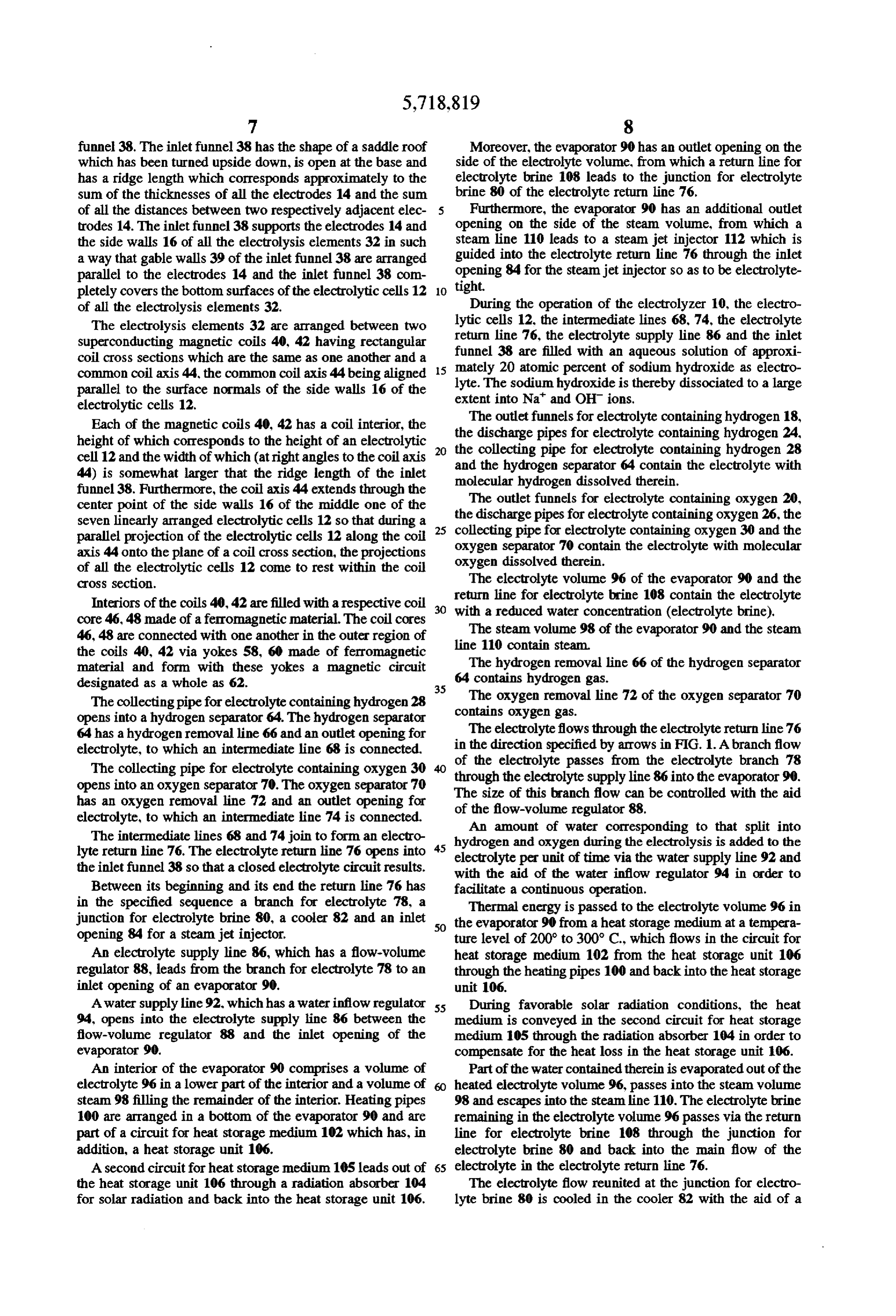
funnel 38. The inlet funnel 38 has the shape of a saddle roof Moreover, the evaporator 90 has an outlet opening on the which has been turned upside down, is open at the base and side of the electrolyte volume, from which a return line for has a ridge length which corresponds approximately to the electrolyte brine 108 leads to the junction for electrolyte sum of the thicknesses of all the electrodes 14 and the sum brine 80 of the electrolyte return line 76. of all the distances between two respectively adjacent elec Furthermore, the evaporator 90 has an additional outlet trodes 14. The inlet funnel 38 supports the electrodes 14 and opening on the side of the steam volume, from which a the side walls 16 of all the electrolysis elements 32 in such steam line 110 leads to a steam jet injector 112 which is a way that gable walls 39 of the inlet funnel 38 are arranged guided into the electrolyte return line 76 through the inlet parallel to the electrodes 14 and the inlet funnel 38 com tight. opening 84 for the steamjet injector so as to be electrolyte pletely covers the bottom surfaces of the electrolytic cells 12 O of all the electrolysis elements 32. During the operation of the electrolyzer 10, the electro The electrolysis elements 32 are arranged between two lytic cells 12, the intermediate lines 68,74, the electrolyte superconducting magnetic coils 40, 42 having rectangular return line 76, the electrolyte supply line 86 and the inlet coil cross sections which are the same as one another and a funnel 38 are filled with an aqueous solution of approxi common coil axis 44, the common coil axis 44 being aligned mately 5 20 atomic percent of sodium hydroxide as electro lyte. The sodium hydroxide is thereby dissociated to a large parallel to the surface normals of the side walls 16 of the extent into Na and OH ions.
electrolytic cells 12.
The
Each of the magnetic coils 40, 42 has a coil interior, the the discharge outlet funnels for electrolyte containing hydrogen 18, height of which corresponds to the height of an electrolytic 20 the collectingpipes pipe for electrolyte containing hydrogen 24.
for electrolyte containing hydrogen 28 cell 12 and the width of which (at right angles to the coil axis and the hydrogen separator 64 contain the electrolyte with 44) is somewhat larger that the ridge length of the inlet molecular hydrogen dissolved therein. funnel 38. Furthermore, the coil axis 44 extends through the The outlet funnels for electrolyte containing oxygen 20, center point of the side walls 16 of the middle one of the the discharge pipes for electrolyte containing oxygen 26, the seven linearly arranged electrolytic cells 12 so that during a 25 collecting pipe for electrolyte containing oxygen parallel projection of the electrolytic cells 12 along the coil oxygen separator 70 contain the electrolyte with 30 and the molecular axis 44 onto the plane of a coil cross section, the projections oxygen dissolved therein.
of all the electrolytic cells 12 come to rest within the coil cross section. The electrolyte volume 96 of the evaporator 90 and the Interiors of the coils 40, 42 are filled with a respective coil with a line return for electrolyte brine 108 contain the electrolyte reduced water concentration (electrolyte brine), core 46, 48 made of a ferromagnetic material. The coil cores 46, 48 are connected with one another in the outer region of lineThe110steam volume 98 of the evaporator 90 and the steam contain steam.
the coils 40, 42 via yokes 58, 60 made of ferromagnetic
The material and form with these yokes a magnetic circuit 64 contains hydrogen hydrogen removal line 66 of the hydrogen separator designated as a whole as 62. 35 gas.
The collecting pipe for electrolyte containing hydrogen 28 contains The oxygen removal line 72 of the oxygen separator 70 opens into a hydrogen separator 64. The hydrogen separator oxygen gas.
64 has a hydrogenremoval line 66 and an outlet opening for The electrolyte flows through the electrolyte return line 76 electrolyte, to which an intermediate line 68 is connected. in the direction specified by arrows in FIG. 1. Abranch flow The collecting pipe for electrolyte containing oxygen 30 through of the electrolyte passes from the electrolyte branch 78 opens into an oxygen separator 70. The oxygen separator 70 The the electrolyte supply line 86 into the evaporator 90. size of this branch flow can be controlled with the aid has an oxygen removal line 72 and an outlet opening for of the flow-volume regulator 88.
electrolyte, to which an intermediate line 74 is connected. An amount of water corresponding to that split into The intermediate lines 68 and 74 join to form an electro 45 hydrogen and oxygen during the electrolysis is added to the lyte return line 76. The electrolyte return line 76 opens into electrolyte per unit of time via the water supply line 92 and the inlet funnel 38 so that a closed electrolyte circuit results. with the aid of the water inflow regulator 94 in order to Between its beginning and its end the return line 76 has facilitate a continuous operation.
in the specified sequence a branch for electrolyte 78, a Thermal energy is passed to the electrolyte volume 96 in junction for electrolyte brine 80, a cooler 82 and an inlet 50 the evaporator 90 from a heat storage medium at a tempera opening 84 for a steam jet injector. ture level of 200° to 300° C., which flows in the circuit for An electrolyte supply line 86, which has a flow-volume heat storage medium 102 from the heat storage unit 106 regulator 88, leads from the branch for electrolyte 78 to an through the heating pipes 100 and back into the heat storage inlet opening of an evaporator 90. unit 106.
A water supply line 92, which has a water inflow regulator 55 During favorable solar radiation conditions, the heat 94, opens into the electrolyte supply line 86 between the medium is conveyed in the second circuit for heat storage flow-volume regulator 88 and the inlet opening of the medium 105 through the radiation absorber 104 in order to evaporator 90. compensate for the heat loss in the heat storage unit 106. An interior of the evaporator 90 comprises a volume of Part of the water contained therein is evaporated out of the electrolyte 96 in a lower part of the interior and a volume of heated electrolyte volume 96, passes into the steam volume steam 98 filling the remainder of the interior. Heating pipes 98 and escapes into the steam line 110. The electrolyte brine 100 are arranged in a bottom of the evaporator 90 and are remaining in the electrolyte volume 96 passes via the return part of a circuit for heat storage medium 102 which has, in line for electrolyte brine 108 through the junction for addition, a heat storage unit 106. electrolyte brine 80 and back into the main flow of the A second circuit for heat storage medium 105 leads out of 65 electrolyte in the electrolyte return line 76. the heat storage unit 106 through a radiation absorber 104 The electrolyte flow reunited at the junction for electro for solar radiation and back into the heat storage unit 106. lyte brine 80 is cooled in the cooler 82 with the aid of a
Page 11
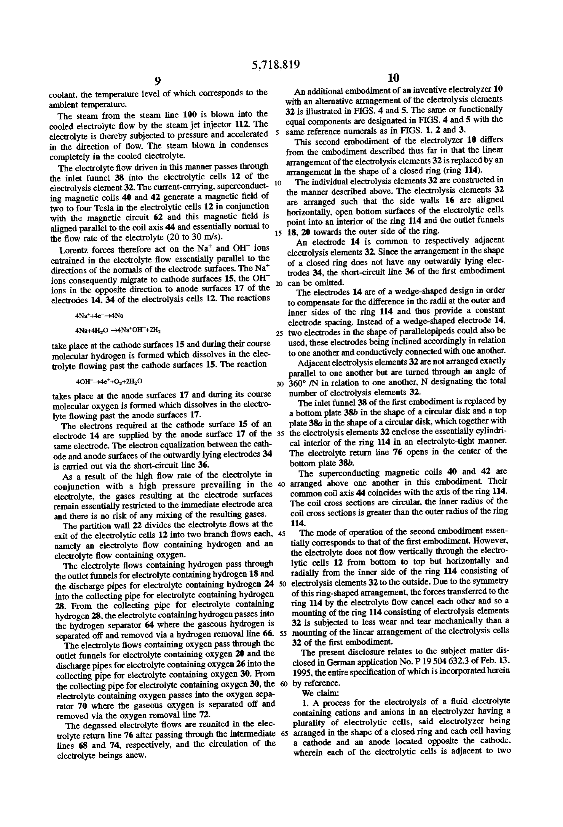
coolant, the temperature level of which corresponds to the An additional embodiment of an inventive electrolyzer 10 ambient temperature. with an alternative arrangement of the electrolysis elements The steam from the steam line 100 is blown into the 32 is illustrated in FIGS. 4 and 5. The same or functionally cooled electrolyte flow by the steam jet injector 112. The equal components are designated in FIGS. 4 and 5 with the electrolyte is thereby subjected to pressure and accelerated same reference numerals as in FIGS. 1, 2 and 3. in the direction of flow. The steam blown in condenses This second embodiment of the electrolyzer 10 differs from the embodiment described thus far in that the linear completely in the cooled electrolyte.
The electrolyte flow driven in this manner passes through arrangement arrangement of the electrolysis elements 32 is replaced by an in the shape of a closed ring (ring 114).
the inlet funnel 38 into the electrolytic cells 12 of the O The individual electrolysis elements 32 are constructed in electrolysis element 32. The current-carrying, superconduct the manner described above. The electrolysis elements 32 ing magnetic coils 40 and 42 generate a magnetic field of two to four Tesla in the electrolytic cells 12 in conjunction are arranged such that the side walls 16 are aligned with the magnetic circuit 62 and this magnetic field is point into an open horizontally, bottom surfaces of the electrolytic cells interior of the ring 114 and the outlet funnels aligned parallel to the coil axis 44 and essentially normal to 15 18, 20 towards the outer side of the ring. the flow rate of the electrolyte (20 to 30 m/s). An electrode 14 is common to respectively adjacent Lorentz forces therefore act on the Na' and OH ions electrolysis elements 32. Since the arrangement in the shape entrained in the electrolyte flow essentially parallel to the of a closed ring does not have any outwardly lying elec directions of the normals of the electrode surfaces. The Na trodes 34, the short-circuit line 36 of the first embodiment ions consequently migrate to cathode surfaces 15, the OH can be omitted.
ions in the opposite direction to anode surfaces 17 of the The electrodes 14 are of a wedge-shaped design in order electrodes 14, 34 of the electrolysis cells 12. The reactions to compensate for the difference in the radii at the outer and 4Na-4e-4Na inner sides of the ring 114 and thus provide a constant electrode spacing. Instead of a wedge-shaped electrode 14, 4Na+4HO-4NaOH+2H 25 two electrodes in the shape of parallelepipeds could also be take place at the cathode surfaces 15 and during their course used, these electrodes being inclined accordingly in relation molecular hydrogen is formed which dissolves in the elec to Adjacent one another and conductively connected with one another. electrolysis elements 32 are not arranged exactly trolyte flowing past the cathode surfaces 15. The reaction parallel to one another but are turned through an angle of 30 360° fN in relation to one another, N designating the total takes place at the anode surfaces 17 and during its course number of electrolysis elements 32.
molecular oxygen is formed which dissolves in the electro a bottom The inlet funnel 38 of the first embodiment is replaced by lyte flowing past the anode surfaces 17. plate 38b in the shape of a circular disk and a top The electrons required at the cathode surface 15 of an 35 plate 38a in the shape of a circular disk, which together with electrode 14 are supplied by the anode surface 17 of the the electrolysis elements 32 enclose the essentially cylindri same electrode. The electron equalization between the cath cal interior of the ring 114 in an electrolyte-tight manner. ode and anode surfaces of the outwardly lying electrodes 34 The electrolyte return line 76 opens in the center of the is carried out via the short-circuit line 36. bottom plate 38b.
As a result of the high flow rate of the electrolyte in The superconducting magnetic coils 40 and 42 are conjunction with a high pressure prevailing in the arranged above one another in this embodiment. Their electrolyte, the gases resulting at the electrode surfaces common coil axis 44 coincides with the axis of the ring 114. remain essentially restricted to the immediate electrode area The coil cross sections are circular, the inner radius of the and there is no risk of any mixing of the resulting gases. coil cross sections is greater than the outer radius of the ring The partition wall 22 divides the electrolyte flows at the 114.
exit of the electrolytic cells 12 into two branch flows each, 45 The mode of operation of the second embodiment essen namely an electrolyte flow containing hydrogen and an tially corresponds to that of the first embodiment. However, electrolyte flow containing oxygen. the electrolyte does not flow vertically through the electro The electrolyte flows containing hydrogen pass through lytic cells 12 from bottom to top but horizontally and the outlet funnels for electrolyte containing hydrogen 18 and radially from the inner side of the ring 114 consisting of the discharge pipes for electrolyte containing hydrogen 24 SO electrolysis elements 32 to the outside. Due to the symmetry into the collecting pipe for electrolyte containing hydrogen of this ring-shaped arrangement, the forces transferred to the 28. From the collecting pipe for electrolyte containing ring 114 by the electrolyte flow cancel each other and so a hydrogen 28, the electrolyte containing hydrogen passes into mounting of the ring 114 consisting of electrolysis elements the hydrogen separator 64 where the gaseous hydrogen is 32 is subjected to less wear and tear mechanically than a separated off and removed via a hydrogen removal line 66. 55 mounting of the linear arrangement of the electrolysis cells The electrolyte flows containing oxygen pass through the 32 of the first embodiment.
outlet funnels for electrolyte containing oxygen 20 and the The present disclosure relates to the subject matter dis discharge pipes for electrolyte containing oxygen 26 into the closed in German application No. P 19504 632.3 of Feb. 13, collecting pipe for electrolyte containing oxygen 30. From 1995, the entire specification of which is incorporated herein the collecting pipe for electrolyte containing oxygen 30, the by reference.
electrolyte containing oxygen passes into the oxygen sepa We claim:
rator 70 where the gaseous oxygen is separated off and 1. A process for the electrolysis of a fluid electrolyte removed via the oxygen removal line 72. containing cations and anions in an electrolyzer having a The degassed electrolyte flows are reunited in the elec plurality of electrolytic cells, said electrolyzer being trolyte return line 76 after passing through the intermediate 65 arranged in the shape of a closed ring and each cell having lines 68 and 74, respectively, and the circulation of the a cathode and an anode located opposite the cathode, electrolyte beings anew. wherein each of the electrolytic cells is adjacent to two
Page 12
additional electrolytic cells and a current path is closed least 20 m/s and the component of the magnetic field at right between adjacent cathodes and anodes, a magnetic field is angles to the flow rate of the electrolyte is at least two Tesla. applied to the electrolytic cells and a relative movement 20. Process as defined in claim 1, characterized in that the between the magnetic field and the electrolyte is generated magnetic field is generated by superconducting coils. so that on account of the effect of Lorentz forces the cations 21. Process as defined in claim 1, characterized in that a migrate to the cathodes and the anions to the anodes, and liquid is used as electrolyte.
products of electrolysis are formed on the cathodes and on 22. Process as defined in claim 1, characterized in that the the anodes in electrolytic reactions, the charge equalization energy stored in the magnetic field is used for the peak load necessary for the electrolytic reactions being carried out by service in electrical networks.
said closed current paths. 10 2. Process as defined in claim 1, characterized in that the 23. Process as defined in claim 1, characterized in that the magnetic field is stationary and that a flow of the electrolyte electrolyte is water and a product of electrolysis is hydrogen. relative to the magnetic field is generated. 24. An electrolyzer for the electrolysis of a fluid 3. Process as defined in claim 2. characterized in that such electrolyte, comprising a plurality of electrolytic cells, each a high pressure is generated in the electrolytic cell and/or 15 cell having a cathode and an anode located opposite the such a high flow rate of the electrolyte relative to the cathode, wherein said plurality of electrolytic cells is electrodes that the products of electrolysis essentially do not arranged in the shape of a closed ring and the electrolyzer mix with one another. has conductive connections between adjacent cathodes and 4. Process as defined in claim 2, characterized in that anodes, a device for generating a magnetic field penetrating several electrolytic cells each have a branch flow of the 20 the electrolytic cells and a device for generating a relative electrolyte flowing through them. movement between the magnetic field and the electrolyte. 5. Process as defined in claim 2, characterized in that the 25. Electrolyzer as defined in claim 24, characterized in electrolyte is conveyed in a circuit. that the electrolyzer has a device for generating an electro 6. Process as defined in claim 2, characterized in that the lytic flow.
flow of the electrolyte is generated with the aid of a 25 26. Electrolyzer as defined in claim 25, characterized in mechanical pump. that the electrolyzer has an electrolyte circuit with an elec 7. Process as defined in claim. 6, characterized in that the trolyte return line.
pump is driven by a thermal engine. 27. Electrolyzer as defined in claim 25, characterized in 8. Process as defined in claim 6, characterized in that the that the electrolyzer has a magnetohydrodynamic pump for pump is driven by water power. 30 generating an electrolyte flow.
9. Process as defined in claim 2, characterized in that the 28. Electrolyzer as defined in claim 25, characterized in flow of the electrolyte is generated with the aid of a that the electrolyzer has a steamjetinjector for generating an magnetohydrodynamic pump. electrolyte flow.
10. Process as defined in claim 2, characterized in that the 29. Etectrolyzer as defined in claim 28, characterized in flow of the electrolyte is generated with the aid of a steam 35 that the electrolyzer has an evaporator for the partial evapo jet injector. ration of the electrolyte.
11. Process as defined in claim 10, characterized in that 30. Electrolyzer as defined in claim 29, characterized in the injected steam is generated by partial evaporation of the that the electrolyte is an aqueous solution. electrolyte. 31. Electrolyzer as defined in claim 29, characterized in 12. Process as defined in claim 11, characterized in that an that the electrolyte is an azeotropic mixture. aqueous solution is used as electrolyte. 32. Electrolyzer as defined in claim 28, characterized in 13. Process as defined in claim 11, characterized in that an that the electrolyzer has a radiation absorber for absorbing azeotropic mixture is used as electrolyte. solar energy.
14. Process as defined in claim 11, characterized in that 33. Electrolyzer as defined in claim 32, characterized in the heatrequired to generate the injected steam is taken from 45 that the electrolyzer has a heat storage unit for temporarily a heated working medium of a thermal power station. storing the thermal energy absorbed by the radiation 15. Process as defined in claim 10, characterized in that absorber.
the heat required for the steam generation is obtained from 34. Electrolyzer as defined in claim 28, characterized in solar energy. that the electrolyzer has a device for cooling the electrolyte, 16. Process as defined in claim 15, characterized in that SO said device being arranged in front of the steamjet injector the heat required for the steam generation is temporarily in the flow direction of the electrolyte.
stored in a heat storage unit. 35. Electrolyzer as defined in claim 24, characterized in 17. Process as defined in claim 10, characterized in that that the electrolyzer has at least one superconducting mag the heat required for the steam generation is obtained netic coil.
geothermally. 55 36. Electrolyzer as defined in claim 24, characterized in 18. Process as defined in claim 10, characterized in that that the electrolytic cell of the electrolyzer is filled with a the electrolyte is cooled prior to the injection of the steam liquid electrolyte.
such that the injected steam condenses essentially com 37. Electrolyzer as defined in claim 24, characterized in pletely in the electrolyte. that the electrolytic cells have bipolar electrodes. 19. Process as defined in claim 1, characterized in that the flow rate of the electrolyte relative to the magnetic field is at ck :: 3: e :
Provenance
- Collection
- Cited prior art
- Original PDF
- patentimages.storage.googleapis.com →
- Filed
- 1996-02-13
- Pages
- 12
- Method
- pdftotext (the PDF's own text layer) + pdftoppm 300dpi page scans
- Source
- Google Patents bibliographic record
- Granted
- 1998-02-17
- Inventors
- Walter Peschka; Gottfried Schneider; Deutsches Zentrum fuer Luft und Raumfahrt eV
- Transcribed from
- patentimages.storage.googleapis.com →