patent · US5690797
Hydrogen and oxygen gas generating system
25 November 1997
Page 1 — bibliographic record
III
United States Patent (19) 11 Patent Number: 5,690,797 Harada et al. 45) Date of Patent: Nov. 25, 1997 54 HYDROGEN AND OXYGEN GAS 4,822,469 4/1989 Shimomura et al. ................... 204/230 GENERATING SYSTEM 5,037,518 8/1991 Young et al. ........................... 204/230 75 Inventors: Hiroyuki Harada, Tokyo; Takashi Primary Examiner-Donald R. Valentine Sasaki, Hyogo; Kiyoshi Hirai, Hyogo; Attorney, Agent, or Firm-Sughrue. Mion.Zinn.Macpeak & Shinichi Yasui, Hyogo; Hiroko Seas, PLLC
Kobayashi, Hyogo; Mamoru Nagao, 57 ABSTRACT
Osaka, all of Japan 73 Assignees: Mitsubishi Corporation, Tokyo; A hydrogen/oxygen gas generating system includes a deion Shinko Pantec Co., Ltd., Hyogo, both ized water container and a cell for water electrolysis having of Japan anode and cathode compartments, the cell being submerged in deionized water in the container. Oxygen gas generated in the anode compartment is channeled to an oxygen gas (21) Appl. No.: 588,336 separating chamber defined in the container at its top 22 Filed: Jan. 18, 1996 whereas hydrogen gas generated in the cathode compart ment is channeled to a gas/liquid separator. The pressures of (30) Foreign Application Priority Data these gases are detected, and in accordance with the detected Jan. 18, 1995 JP Japan .................................... 7-0.24737 gas pressures, a first gas piping line for delivering oxygen gas outward from the oxygen gas separating chamber and a (51) Int. Cl. ..................... C25B 9/00; C25B 15/08 second gas piping line for delivering hydrogen gas outward (52) U.S. Cl. ......................... 204/229; 204/230; 204/238; from the separator are controlled such that the differential 204/239; 204/266 pressure between the gases may fall in a limited range. Water 58) Field of Search ..................................... 204/229, 230, level in the oxygen gas separating chamber and water level 204/238,239, 266 in the gas/liquid separator are detected, and the detected levels are utilized to control the pressures and the supply of 56 References Cited deionized water into the container. The system can generate hydrogen and oxygen gases of high purity under high
SOS.
3,616,436 10/1971 Haas.................................... 204/230 X 4.002552 1/1977 Bunn, Jr. 204/230 X 4.533,451 8/1985 Kumazawa ..... so 204/229 16 Claims, 4 Drawing Sheets
Page 2
Drawing sheet — no readable text.
Page 3
Drawing sheet — no readable text.
Page 4
Drawing sheet — no readable text.
Page 5
Drawing sheet — no readable text.
Page 6
HYDROGEN AND OXYGEN GAS actually employed that an electrolytic apparatus capable of GENERATING SYSTEM generating hydrogen and oxygen gases through electrolysis BACKGROUND OF THE INVENTION of water is installed in a plant where hydrogen and oxygen 1. Field of the Invention gases are consumed. Since only necessary amounts of hydrogen and oxygen gases can be generated in the plant
This invention relates to a system for generating hydrogen only when necessary, this solution eliminates a need for and oxygen gases of high purity by direct electrolysis of storage and transportation and avoids the danger associated deionized water.
2. Prior Art therewith. However, since conventional water electrolyzing apparatus
Hydrogen and oxygen gases of high purity are useful in 10. a gas compressor generate a gas under low pressure, in most cases, must be used to pressurize the gas before film formation steps for forming thin and thick films such as use. Then the overall facility is increased in size. The actual silicon oxide films. CVD films, and epitaxially grown films introduction of the electrolytic apparatus in the plant is and heat treatment steps in the semiconductor manufacturing disadvantageous from the points of view of installation cost process, for preventing corrosion of coolant water piping and maintenance service unless the amount of gas consump lines in nuclear power plants, and for cooling in thermal tion is above a certain level. Therefore, only a few plants power plants, as well as in ceramic, fine ceramic and other 15 have water electrolyzing apparatus incorporated in practice. industrial fields. Additionally, the use of a gas compressor raises the problem In the prior art, hydrogen gas is generally obtained by that lubricant oil for the compressor can be taken into purifying by-product gases resulting from the petrochemical semiconductor and other products as hydrocarbon impurities and soda industries. Hydrogen gas is processed into a 20 as previously mentioned. For this and other reasons, semi convenient form for transportation and storage, for example, conductor manufacturers hesitated to introduce electrolytic by compressing the gas by a compressor to fill a cylinder apparatus in their plants.
with hydrogen gas under high pressure or by cooling and With respect to electrolysis of water, it is well known that liquefying the gas before it is delivered to semiconductor the pressures of hydrogen and oxygen gases will increase if manufacturing facilities for use. However, cylinders filled 25 the amounts of hydrogen and oxygen gases generated with pressurized hydrogen gas are hazardous in that the fill exceed the consumption amounts. Then in theory, it must be pressure itself is dangerous and there is a risk of ignition or possible to generate hydrogen and oxygen gases under explosion due to leakage during transportation or storage. desired pressures without a need for gas compressors. In Additionally, when hydrogen gas is filled under high pres conventionally widely used water electrolyzing cells, sure by compressing it by a gas compressor, hydrocarbon 30 however, the conventional electrolytic cells cannot be impurities can be introduced into the gas from lubricant oil increased in pressure resistance by a choice of material and of the compressor. If such hydrogen gas is used in the structure because of restrictions from the strength of elec semiconductor manufacturing industry, hydrocarbon impu trolyte membranes and sealing properties of cells them rities can deteriorate the quality or reduce the yield of selves. In the prior art, there were available no water semiconductor products. 35 electrolyzing apparatus capable of generating hydrogen and On the other hand, oxygen gas is generally available as oxygen gases under desired pressures without a need for gas liquefied oxygen by cooling air followed by low compressors.
temperature processing. Liquefied oxygen is transported to In semiconductor manufacturing plants, for example, consumption sites such as semiconductor manufacturing hydrogen purifiers utilizing the hydrogen permeability of plants and stored as such. On use, liquefied oxygen is palladium have been widely used. Although hydrogen puri allowed to gasify. Alternatively, oxygen gas is filled in fiers of this type have a maximum service pressure limited cylinders under high pressure which are transported and to less than 10 atm. so that they may fall outside the stored until use. Unlike hydrogen, oxygen is not combustible high-pressure gas handling regulations, they are usually or explosive by itself, but actively supports combustion to operated under a higher pressure within the limited range, permit even iron and other metals to burn and forms strong 45 This is because an increased pressure loss across a palladium explosives when mixed with combustibles. Therefore, like permeation cell in a hydrogen purifier allows the expensive hydrogen, oxygen has a fair chance to create hazard during palladium permeation cell to be reduced in area, achieving transportation, storage and use. Since air is used as a source a cost reduction. Water electrolyzing cells using solid poly for oxygen gas, airborne hydrocarbons and other impurities mer electrolyte membranes, on the other hand, have a can be carried into oxygen gas. Like the hydrogen gas 50 pressure resistance of about 4 atm. If a water electrolysis cell pressurized by a compressor, such contaminated oxygen gas is used by directly combining it with a hydrogen purifier, the can adversely affect the quality and yield of products in the area of a palladium permeation cell in the hydrogen purifier semiconductor industry. must be increased several folds. This is difficult to imple Many problems arise with respect to the transportation ment from the economical point of view. It is then inevitable and storage of cylinders filled with hydrogen or oxygen gas 55 to interpose a gas compressor, which can give rise to the under high pressure. Citizens are now more conscious and problems of reduced product quality and yield by hydrocar feel dangerous about the transportation of such hazardous bon impurities as previously mentioned. The concept of cylinders across city areas or the storage in city areas. In generating hydrogen and oxygen gases in situ by electrolysis fact, the risk of an accident is considerably high. The of water has never been implemented in semiconductor transportation cost is increasing. There is a need to have an manufacturing plants.
implement capable of supplying high purity hydrogen or In order to solve the above-mentioned problems, we oxygen gas in a stable manner without possible contamina devised a hydrogen and oxygen gas generating system tion with hydrocarbons, which implement can eliminate comprising a container filled with deionized water and risks associated with transportation and storage and reduce having received therein a water electrolysis cell for gener the cost of transportation. 65 ating hydrogen and oxygen gases by electrolysis of water. As one solution to the safety problem among the above That is, the arrangement having a water electrolysis cell mentioned problems, it was contemplated convenient and received in a container filled with deionized water is dis
Page 7
closed in Publication of International Patent Application No. to the respective cells through a serial piping line. This 502908/1988 "Method and Apparatus for Electrolysis of proposal does not intend to generate hydrogen gas under Water.” Japanese Patent Publication (JP-B) No. 247591/ high pressure and thus has no function of pressure regula 1989 "Hydrogen Producing System," and Japanese Patent tion. It is then impossible to generate hydrogen gas under Application Kokai (JP-A) No. 33283/1994 "Hydrogen Gen high pressure.
erating System." SUMMARY OF THE INVENTION More particularly, Publication of International Patent
Application No. 502908/1988 "Method and Apparatus for A primary object of the present invention is to provide a Electrolysis of Water" discloses a housing surrounding a cell hydrogen and oxygen gas generating system which can for water electrolysis. Discharge water from the anode is led 10 generate hydrogen and oxygen gases under high pressures to between the housing and the cell. Hydrogen gas can be without a need for gas compressors, eliminate the risk of generated under a somewhat high pressure. A need for a gas hydrogen and oxygen gases being contaminated with hydro compressor is sometimes eliminated. This proposal, carbons resulting from gas compressors, and therefore, however, does not disclose the technique of balancing the deliver pressurized hydrogen and oxygen gases of high pressures on the anode and cathode sides of the water 15 purity at low cost in a highly reliable manner. electrolysis cell, exactly stated, the technique of balancing Another object of the present invention is to provide a the pressures of hydrogen and oxygen gases. A diaphragm hydrogen and oxygen gas generating system comprising a separating the anode and cathode sides, for example, a solid deionized water container and a water electrolysis cell electrolyte membrane can fail if gases are generated under immersed therein, which can control the level of water and higher pressures than the pressure resistance of the dia 20 the pressures of hydrogen and oxygen gases so as to deliver phragm. It is then difficult to generate gases under any pressurized hydrogen and oxygen gases in a stable and safe desired high pressures. Generally in the semiconductor a.
manufacturing field, it is desired to generate hydrogen gas In a first form, the present invention provides a hydrogen under a high pressure in the range that does not interfere with the high-pressure gas handling regulation, that is, about 25 anda water oxygen gas generating system comprising electrolysis cell having anode and cathode com 10 atm., typically about 9.5 atm. Since known diaphragms such as solid electrolyte membranes have a pressure resis partments separated from one another by a diaphragm tance of about 4 or 5 atm. at most, it is difficult to directly and hydrogen gaseswater wherein deionized is electrolyzed to generate oxygen in the anode and cathode compartments, generate hydrogen gas under such a high pressure.
JP-B 247591/1989 "Hydrogen Producing System" dis 30 respectively,an oxygen outflow pipe connected to the anode compart closes that a high pressure pump pumps deionized water into ment of the electrolytic cell for channeling oxygen gas a container or pressure vessel in which a cell for water resulting from electrolysis upward from the anode electrolysis is received. The container has a discharge port with a hydraulic pressure control valve. Deionized water fed compartment, into the container by the pump is discharged from the 35 a hydrogen outflow pipe connected to the cathode com discharge port through the valve so that deionized water in partment of the electrolytic cell for channeling hydrogen gas the container may be maintained at a constant pressure. resulting from electrolysis outward from the cathode Hydrogen and oxygen gases generated in the electrolytic cell compartment, are collected in gas chambers which are defined in an upper a container filled with deionized water, surrounding the portion of the container and divided by a partition in a fluid electrolytic cell and supporting the cell submerged in deion tight manner to prevent intermixing of gases. The respective ized water, the container including an upper portion defining gas chambers at lower ends are in contact with deionized an oxygen gas separating chamber where an upper end of the water in the container whereby the hydraulic pressure of oxygen outflow pipe opens, deionized water is always in balance with the pressures of a deionized water feed means for feeding deionized water hydrogen and oxygen gases. With this arrangement, no 45 into the container.
differential pressure is applied across the diaphragm typi the cell further having a communication port at the bottom cally in the form of a solid electrolyte membrane separating of the anode compartment for communication of deionized the anode and cathode sides. There is no risk of failure of the water between the cell interior and the container interior, diaphragm in the cell even when the pressures of hydrogen a gas/liquid separator disposed outside the container and and oxygen gases are increased. This proposal, however, 50 connected to the cathode compartment of the electrolytic does not disclose the technique of taking out hydrogen and cell through the hydrogen outflow pipe for receiving hydro oxygen gases from the hydrogen and oxygen chambers in gen gas, the container exactly at a volume ratio of 2:1. If the a first gas pressure detecting means for detecting the consumption proportion is not in balance with the generation pressure of oxygen gas accumulating in an upper space of proportion, one gas which is less consumed increases its 55 the oxygen gas separating chamber.
volume. Eventually the one gas expands beyond the lower a second gas pressure detecting means for detecting the end of the partition where the chambers merge with each pressure of hydrogen gas accumulating in an upper space of other and overflows from its own chamber to the other chamber to form detonating gas. Alternatively, water in the the gas/liquid separator, container can flow out through a gas outlet pipe. The system gasa first gas piping line for delivering outward the oxygen accumulating in an upper space of the oxygen gas of this proposal is difficult to operate in a stable and safe separating chamber,
The hydrogen generating system of JP-A 33283/1994 hydrogen a second gas piping line for delivering outward the includes a water tank forming a water chamber in which a liquid separator, gas accumulating in an upper space of the gas/ water electrolyzer consisting of a plurality of electrolytic 65 cells is immersed, thereby eliminating the shortage of water a gas pressure control means for controlling the first and supply to the respective cells as occurring when water is fed second gas piping lines in accordance with the values of gas
Page 8
S 6 pressure detected by the first and second gas pressure In another preferred embodiment, the system further detecting means, to control the pressure of oxygen gas includes a second level detector means for detecting the accumulating in an upper space of the oxygen gas separating level of water in the gas/liquid separator and means for chamber and the pressure of hydrogen gas accumulating in discharging water accumulated in the gas/liquid separator in an upper space of the gas/liquid separator, accordance with the water level in the gas/liquid separator a DC power source for supplying electric power to the detected by the second level detector means. Then the water electrolytic cell, and level below hydrogen gas in the gas/liquid separator is a power regulator coupled to the DC power source for detected, and water in the gas/liquid separator is discharged controlling the power supply to the electrolytic cell so that in accordance with the detected position of the water level. the pressure of hydrogen gas and the pressure of oxygen gas O This allows the water level in the gas/liquid separator to be may reach predetermined pressure values. maintained substantially constant. In the hydrogen and oxygen gas generating system of the In a further preferred embodiment, the system further first form, oxygen gas generated in the anode compartment includes a second level detector means for detecting the of the electrolytic cell is channeled along with deionized level of water in the gas/liquid separator, a discharge conduit water to the oxygen gas separating chamber near the top of 15 connected between the gas/liquid separator and the container the container through the oxygen outflow pipe and accumu for discharging water accumulated in the gas/liquid separa lates in the upper space of the chamber. Hydrogen gas tor therethrough, a pump disposed in the discharge conduit generated in the cathode compartment of the electrolytic cell for pumping water from the gas/liquid separator to the is channeled along with deionized water to the gas/liquid container, and means for actuating the pump in accordance separator through the hydrogen outflow pipe and accumu with the water level in the gas/liquid separator detected by lates in the upper space of the separator. The oxygen gas the accumulating in the upper space of the oxygen gas separat the second level detector means. Then the water carried into ing chamber is channeled to the first gas piping line and gas is returnedseparator
to the from the cell along with hydrogen container. The amount of deionized delivered outward therefrom. The hydrogen gas accumulat ing in the upper space of the gas/liquid separator is chan water to be newly replenished to the container is only the neled to the second gas piping line and delivered outward 25 amount of water consumed by electrolysis. therefrom. In a still further preferred embodiment, the system further The pressure of oxygen gas in the oxygen gas separating includes a second level detector means for detecting the chamber is detected by the first pressure detecting means level of water in the gas/liquid separator, a discharge conduit whereas the pressure of hydrogen gas in the gas/liquid connected between the gas/liquid separator and the container separator is detected by the second pressure detecting 30 for discharging water accumulated in the gas/liquid sepa means. In accordance with the detected pressure values, the rator therethrough, a valve disposed in the discharge pressures of oxygen and hydrogen gases in the oxygen gas conduit, and means for opening and closing the valve in separating chamber and the gas/liquid separator. accordance with the water level in the gas/liquid separator respectively, are controlled by the gas pressure control detected by the second level detector means, the gas pressure means. More specifically, the gas pressure control means 35 control means functioning such that the pressure of hydro functions such that the difference (differential pressure) gen gas accumulating in an upper space of the gas/liquid between the pressure of oxygen gas in the oxygen gas separator may be higher than the pressure of oxygen gas separating chamber and the pressure of hydrogen gas in the accumulating in an upper space of the oxygen gas separating gas/liquid separator may fall within a predetermined range. chamber. Since the system is controlled such that the pres As a result, the differential pressure applied across the 40 sure of hydrogen gas in the gas/liquid separator may be diaphragm in the form of a solid polymer electrolyte mem higher than the pressure of oxygen gas in the oxygen gas brane separating the anode and cathode compartments of the separating chamber, water in the gas/liquid separator can be cell falls within a predetermined range, preventing a failure returned to the container without a need for mechanical of the diaphragm by an excessive differential pressure. The transfer means such as a pump.
differential pressure applied across seals of the cell is also 45 In a still further preferred embodiment, the gas pressure reduced, preventing gas leakage through the seals. control means functions such that the difference between the Consequently, the system can increase the pressure of gas pressure of oxygen gas accumulating in an upper space of generated to a desired high level without inviting the risk of the oxygen gas separating chamber and the pressure of a failure of the diaphragm or gas leakage through the seals hydrogen gas accumulating in an upper space of the gas/ due to a differential pressure. That is, hydrogen and oxygen 50 liquid separator may fall within a predetermined range. gases of high pressures can be delivered without a need for Since the difference between the pressure of oxygen gas in gas compressors, Since the increased pressure of a gas the oxygen gas separating chamber and the pressure of generated allows the partial pressure of moisture in that gas hydrogen gas in the gas/liquid separator is controlled to fall to be relatively reduced, hydrogen and oxygen gases of within the predetermined range, the differential pressure higher purity can be delivered. 55 applied across the diaphragm of the cell is minimized. As a In one preferred embodiment, the system further includes consequence, the pressure of gas generated can be increased. a first level detector means for detecting the level of water In a second form, the present invention provides a hydro in the oxygen gas separating chamber and means for actu gen and oxygen gas generating system comprising ating the deionized water feed means to feed deionized a water electrolysis cell having anode and cathode com water into the container in accordance with the water level partments separated from one another by a diaphragm in the oxygen gas separating chamber detected by the first wherein deionized water is electrolyzed to generate oxygen level detector means. Then the water level in the oxygen gas and hydrogen gases in the anode and cathode compartments, separating chamber is detected, and deionized water is made respectively, up into the container in accordance with the detected posi an oxygen outflow pipe connected to the anode compart tion of the water level. This allows the water level in the 65 ment of the electrolytic cell for channeling oxygen gas oxygen gas separating chamber to be maintained substan resulting from electrolysis upward from the anode tially constant. compartment,
Page 9
a hydrogen outflow pipe connected to the cathode com flow rate of oxygen gas through the leaking branch of the partment of the electrolytic cell for channeling hydrogen gas first gas piping line is controlled. More specifically, control resulting from electrolysis upward from the cathode is made such that the total flow rate of oxygen gas through compartment, the first gas piping line may be one half of the flow rate of a container filled with deionized water, surrounding the hydrogen gas through the second gas piping line. Then the electrolytic cell and supporting the cell submerged in deion gas pressures in the oxygen and hydrogen compartments are maintained substantially equal. Furthermore, either one or ized water, the container including a partition for dividing an both of the flow controllers in the first gas piping line are upper portion of the container into oxygen and hydrogen controlled in accordance with the water level detected by the compartments in a fluid tight manner to prevent any gas 10 second or first leakage therebetween, upper ends of the oxygen and hydro in the hydrogenlevel or detector means (that is, the water level oxygen compartment) whereby the water gen outflow pipes opening in the oxygen and hydrogen level in the hydrogen or oxygen compartment is maintained compartments, respectively, at the predetermined position, which in turn, ensures to a deionized water feed means for feeding deionized water maintain the hydrogen gas flow rate and the oxygen gas flow into the container, 15 rate correctly at a ratio of 2/1. Then as in the first form, the the cell further having a communication port at the bottom differential pressure applied across the diaphragm between of the anode compartment for communication of deionized the anode and cathode compartments of the cell is mini water between the cell interior and the container interior, mized. As a consequence, gases under high pressures can be a first level detector means for detecting the level of water delivered. It is understood that the gas pressure can also be in the oxygen compartment, 20 controlled in terms of the power supplied to the cell. a second level detector means for detecting the level of In a preferred embodiment, the gas flow rate control water in the hydrogen compartment, means controls such that the total flow rate of oxygen gas a first gas piping line for delivering outward the oxygen through the one and other flow controllers of the first gas gas accumulating in an upper space of the oxygen piping line may be one half of the flow rate of hydrogen gas compartment, the first gas piping line having one flow 25 through the second gas piping line. Since the total flow rate controller for controlling the flow rate of outward oxygen of oxygen gas through the first gas piping line is 4 of the gas flow and the first gas piping line including a branch for flow rate of hydrogen gas through the second gas piping line, leaking oxygen gas and another flow controller in the branch the gas pressures in the oxygen and hydrogen compartments for controlling the flow rate of leaking oxygen gas flow, are maintained substantially equal. The differential pressure a second gas piping line for delivering outward the 30 applied across the diaphragm between the anode and cath hydrogen gas accumulating in an upper space of the hydro ode compartments of the cell is then minimized. gen compartment, the second gas piping line having a flow The following preferred embodiments apply to both the meter for measuring the flow rate of hydrogen gas, first and second forms of the invention. a gas flow rate control means for controlling at least one In a still further preferred embodiment, the system further of the flow controllers of the first gas piping line in accor 35 includes a loop connected to the container and having a dance with a measurement of the flow meter of the second pump, a heat exchanger, an ion exchanger, and a filter gas piping line and controlling the other flow controller in arranged in series for circulating deionized water between the branch of the first gas piping line in accordance with the the container and the loop. The deionized water in the water level detected by the second or first level detector container is continuously cooled and purified by circulating neaS, the deionized water through the loop. This prevents the the deionized water feed means being actuated to feed deionized water from raising its temperature and from being deionized water into the container in accordance with the contaminated with materials dissolved out from the con water level detected by the first or second level detector tainer and the cell. As a result, gases of higher purity can be canS 45 generated.
a DC power source for supplying electric power to the In a still further preferred embodiment, the system further electrolytic cell, and includes a deionized water supply line connected to an outlet a power regulator coupled to the DC power source for port of the container and the communication port of the controlling the power supply to the electrolytic cell in electrolytic cell and having a pump, aheat exchanger, an ion accordance with the pressure detected by a gas pressure 50 exchanger, and a filter arranged in series for supplying detecting means in the second or first gas piping line so that deionized water from the container to the cell through the the gas pressure may reach a predetermined pressure value. supply line. While deionized water is supplied from the In the system of the second form, the oxygen and hydro containerthe to the cell, it is purified and cooled. This prevents deionized water from temperature rise and gen gases generated in the anode and cathode compartments of the cell are independently channeled to the oxygen and 55 contamination, enabling to generate gases of higher purity. hydrogen compartments in the upper portion of the In a still further preferred embodiment, the system further container, respectively. Since the oxygen and hydrogen includes a cooling means embracing the container for cool compartments are separated by the partition, no intermixing ing the container with coolant, typically cooling water or of oxygen and hydrogen gases occurs. The oxygen and cooling air. Cooling the container from the outside can hydrogen gases accumulated in the oxygen and hydrogen prohibit any abnormal temperature rise even when large compartments of the container are channeled to the first and amounts of gases are generated.
second gas piping lines, respectively, and then delivered In a still further preferred embodiment, each of the first outward. and second gas piping lines includes a pressure retaining The flow rate of hydrogen gas through the second gas means which opens to allow gas flow when the applied pressure is not lower than a preset value and closes to piping line is detected. In accordance with this detected flow 65 prevent rate, the sum of the flow rate of oxygen gas through the gas flow when the applied pressure is lower than the outward delivery section of the first gas piping line and the preset value. The pressure retaining means in the first and
Page 10
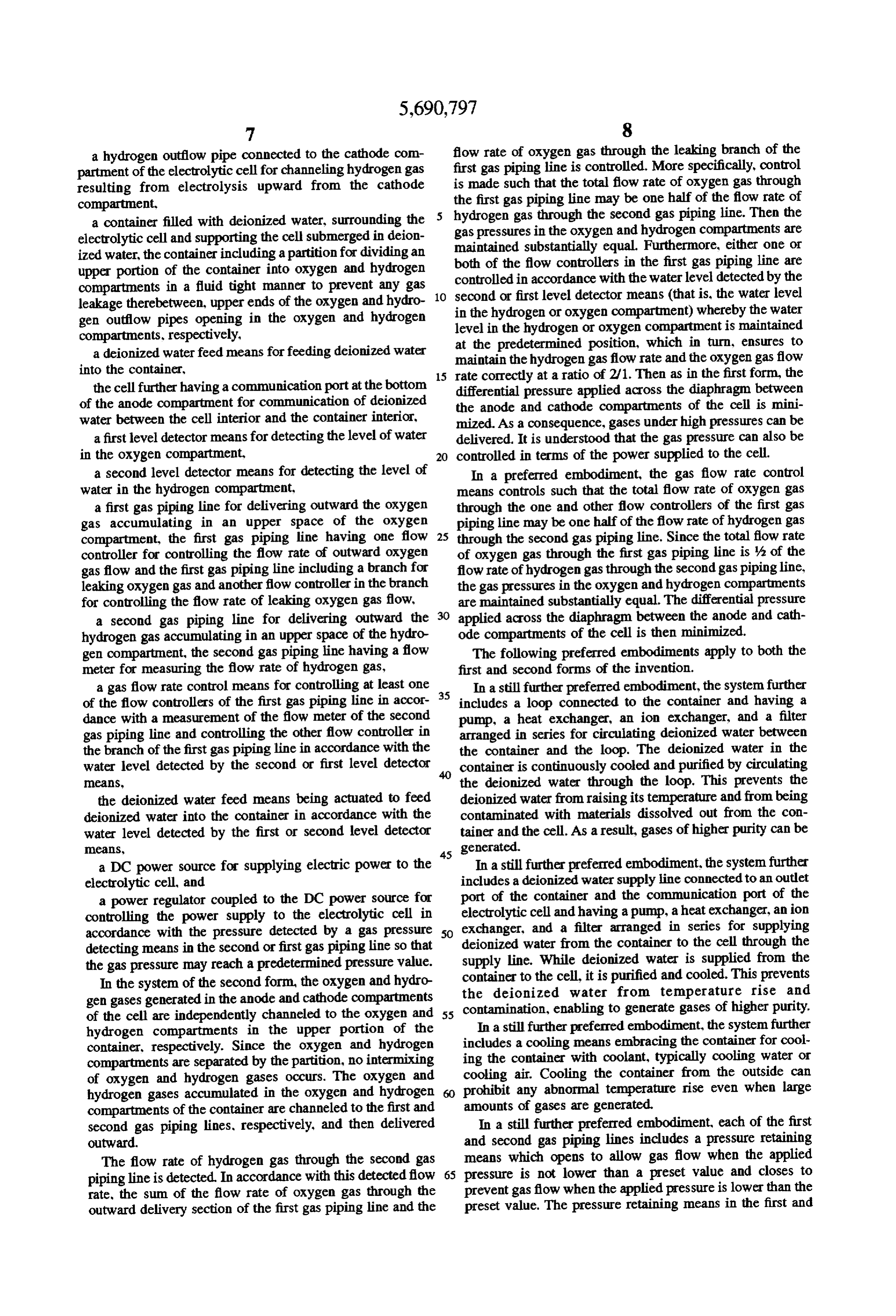
second gas piping lines prevent outward delivery of oxygen electrolysis of deionized water in the anode compartment and hydrogen gas insofar as the pressure of oxygen gas in upward and releasing it into an oxygen gas separating the upper space of the oxygen gas separating chamber (or chamber 7A of the container 7 to be described later. Also at oxygen compartment) and the pressure of hydrogen gas in the top of the cell 1, specifically at the top of the cathode the upper space of the gas/liquid separator (or hydrogen compartment is connected a hydrogen outflow pipe 4 for compartment) do not exceed the predetermined pressure channeling hydrogen gas generated by electrolysis of deion values. This prevents the gas pressures from losing balance ized water in the cathode compartment to guide it outside the even in a situation where gases might be consumed in container 7. An anodic electricity feeder plate 5 is in contact amounts in excess of the amounts of gases generated. Stable with the outer surface of the cell 1 on its anode compartment and safe gas delivery is possible. Oxygen and hydrogen 10 side and a cathodic electricity feeder plate 6 is in contact gases under desired high pressures can be delivered to the with the outer surface of the cell 1 on its cathode compart sites of consumption. ment side. The feeder plate 6 also serves as a support for In a still further preferred embodiment, the container is supporting the water electrolysis cell 1 in the container 7. A DC power source 53 is electrically connected to the cell 1 for loaded with an ion exchange resin. The deionized water in supplying the container is continuously purified by the ion exchange 15 5 and theancathodic electric power between the anodic feeder plate feeder plate/support 6 for effecting resin, permitting the gases of higher purity to be generated. electrolysis of deionized water. A power regulator 52 is In a still further preferred embodiment, at least one of the electrically coupled with the DC power source 53 for first and second gas piping lines includes a gas dryer. Since controlling its power supply.
moisture in the oxygen and/or hydrogen gas is removed by the gas dryer, the gas of higher purity can be delivered. 20 in The water electrolysis cell 1 as a whole is accommodated the container 7 which is filled with deionized water, so
In a still further preferred embodiment, the diaphragm is that the cell 1 is immersed in deionized water. The container a membrane of a solid polymer electrolyte. 7 is configured and sized such that the cell 1 supported In a still further preferred embodiment, the container is upright by the cathodic feeder plate/support 7 is received made of stainless steel and has a passivated oxide film inside the container 7 and deionized water surrounds the formed on the inner surface thereof. The stainless steel with outside of the cell 1. The container 7 includes an upper a passivated oxide lining minimizes dissolution of compo portion which is disposed above the cell 1 and defines an nents of the container into deionized water, preventing oxygen gas separating chamber 7A. The distal end of the contamination of deionized water and allowing gases of oxygen outflow pipe 3 opens in the oxygen gas separating higher purity to be generated. 30 chamber 7A. The hydrogen outflow pipe 4 is extended
BRIEF DESCRIPTION OF THE DRAWINGS
outside the container 7 and connected to a gas/liquid sepa rator 32 to be described later.
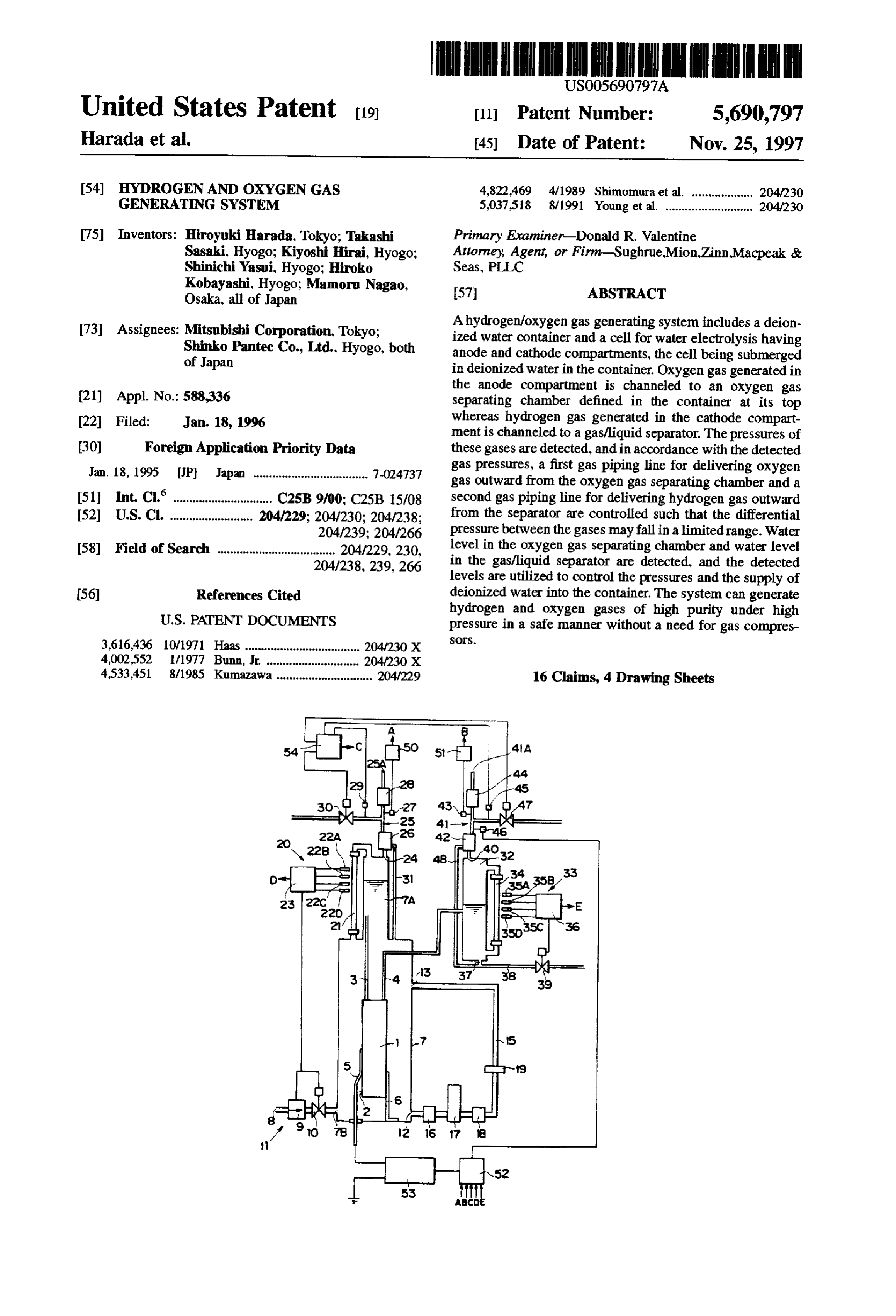
These and further features of the present invention will be The deionized water container 7 is provided at the bottom apparent with reference to the following description and with a water intake port 7B. An external water feed conduit drawings, wherein: 35 8 is connected to the intake port 7B through a feed pump 9 FIG. 1 is a block diagram showing a hydrogen and oxygen and a control valve 10 for pumping and controlling deion generating system according to a first embodiment of the ized waterflow therethrough. The feed conduit 8, feed pump invention. 9 and control valve 10 form a deionized water feed means 11 for feeding deionized water into the container 7 in a
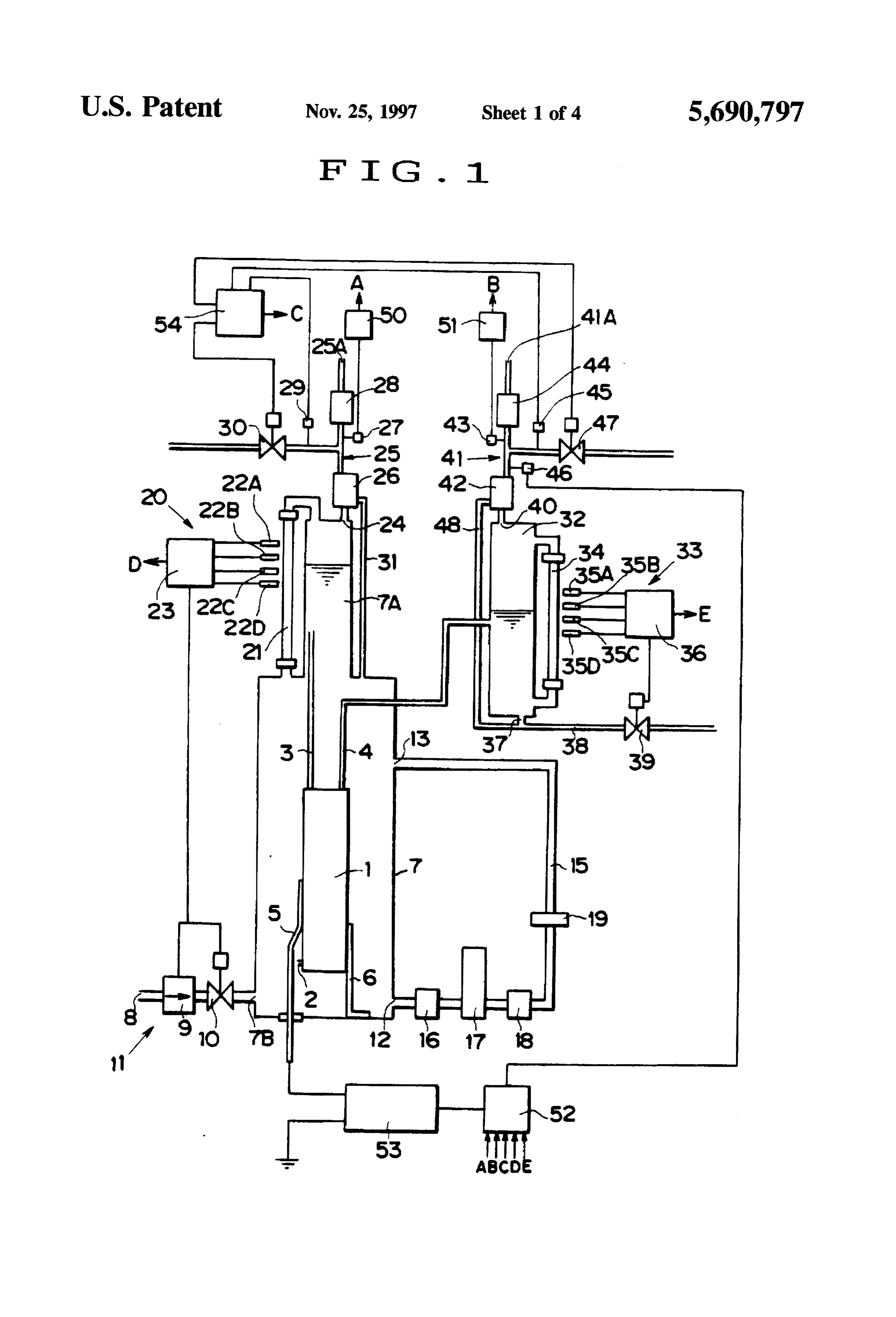
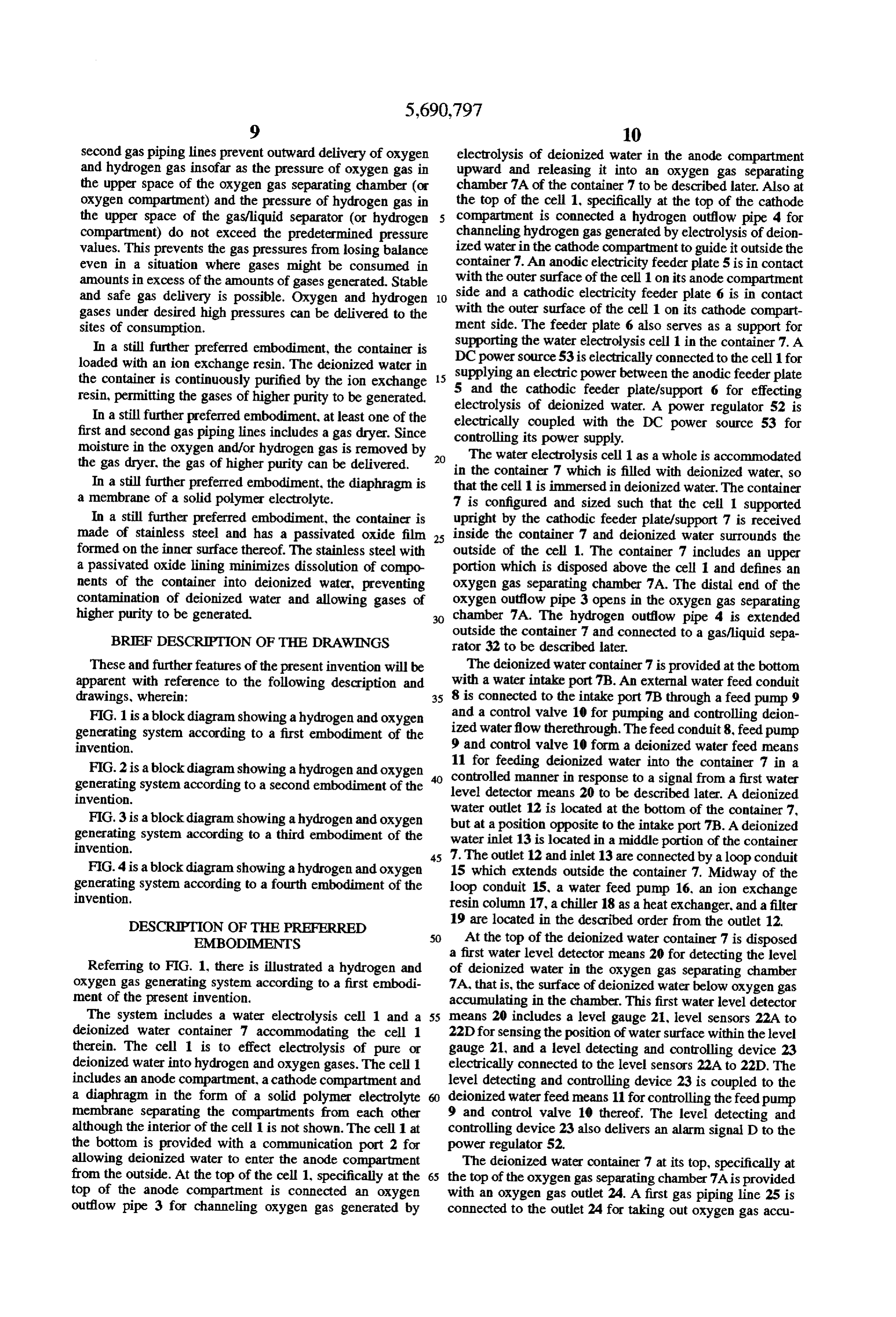
FIG. 2 is a block diagram showing a hydrogen and oxygen controlled generating system according to a second embodiment of the 40 level manner in response to a signal from a first water invention. detector means 20 to be described later. A deionized water outlet 12 is located at the bottom of the container 7,
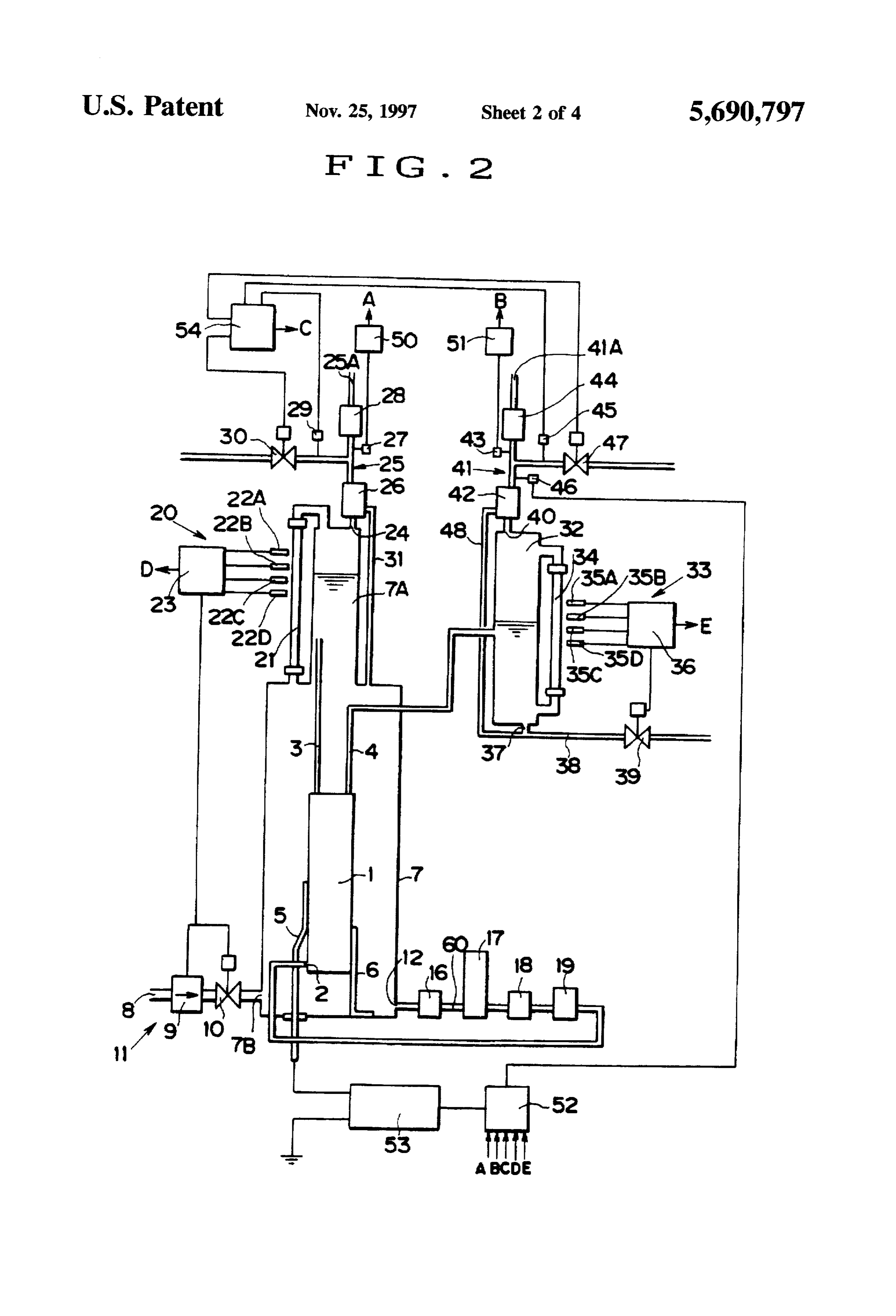
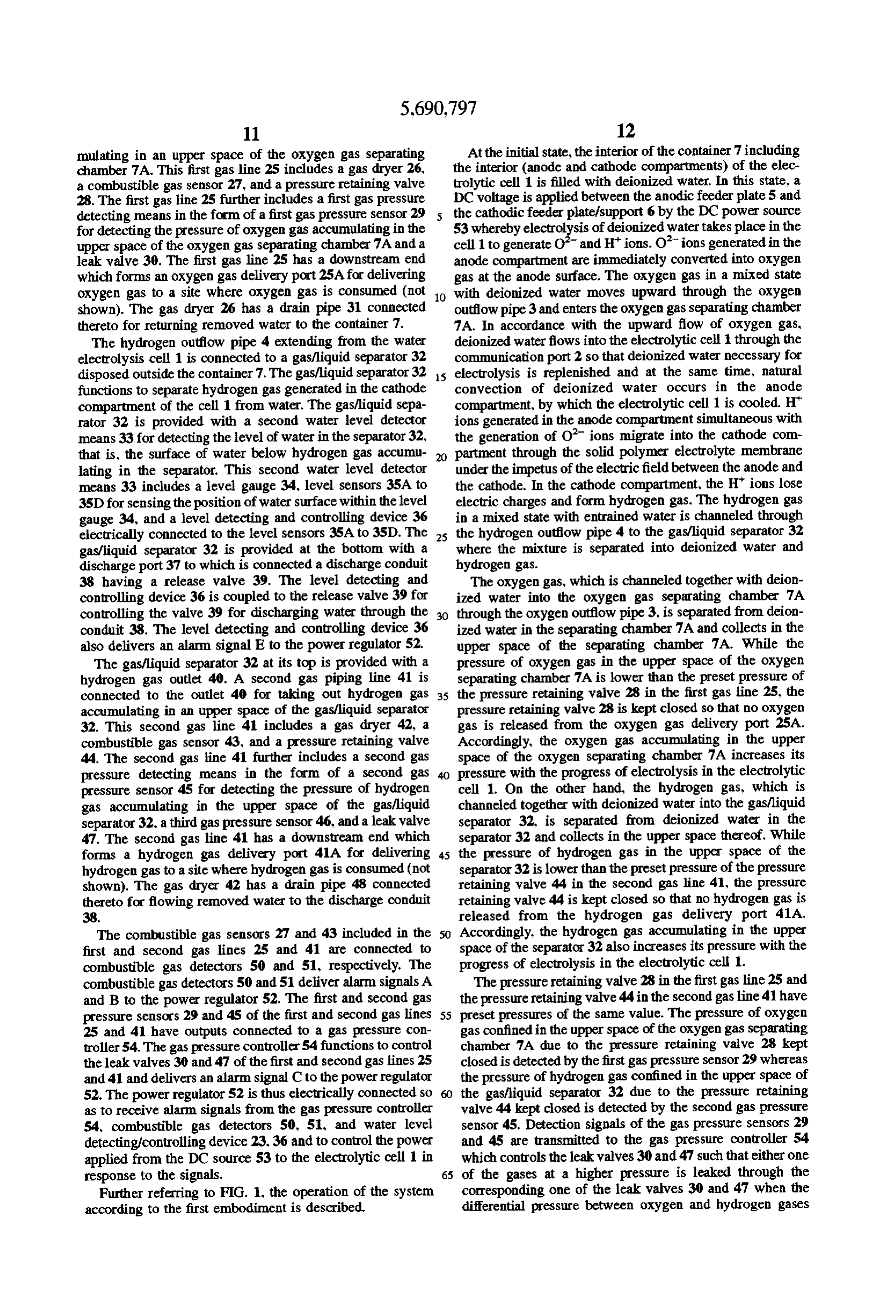
FIG. 3 is a block diagram showing a hydrogen and oxygen but at a position opposite to the intake port 7B. A deionized generating system according to a third embodiment of the water inlet 13 is located in a middle portion of the container invention.
45 7. The outlet 12 and inlet 13 are connected by a loop conduit
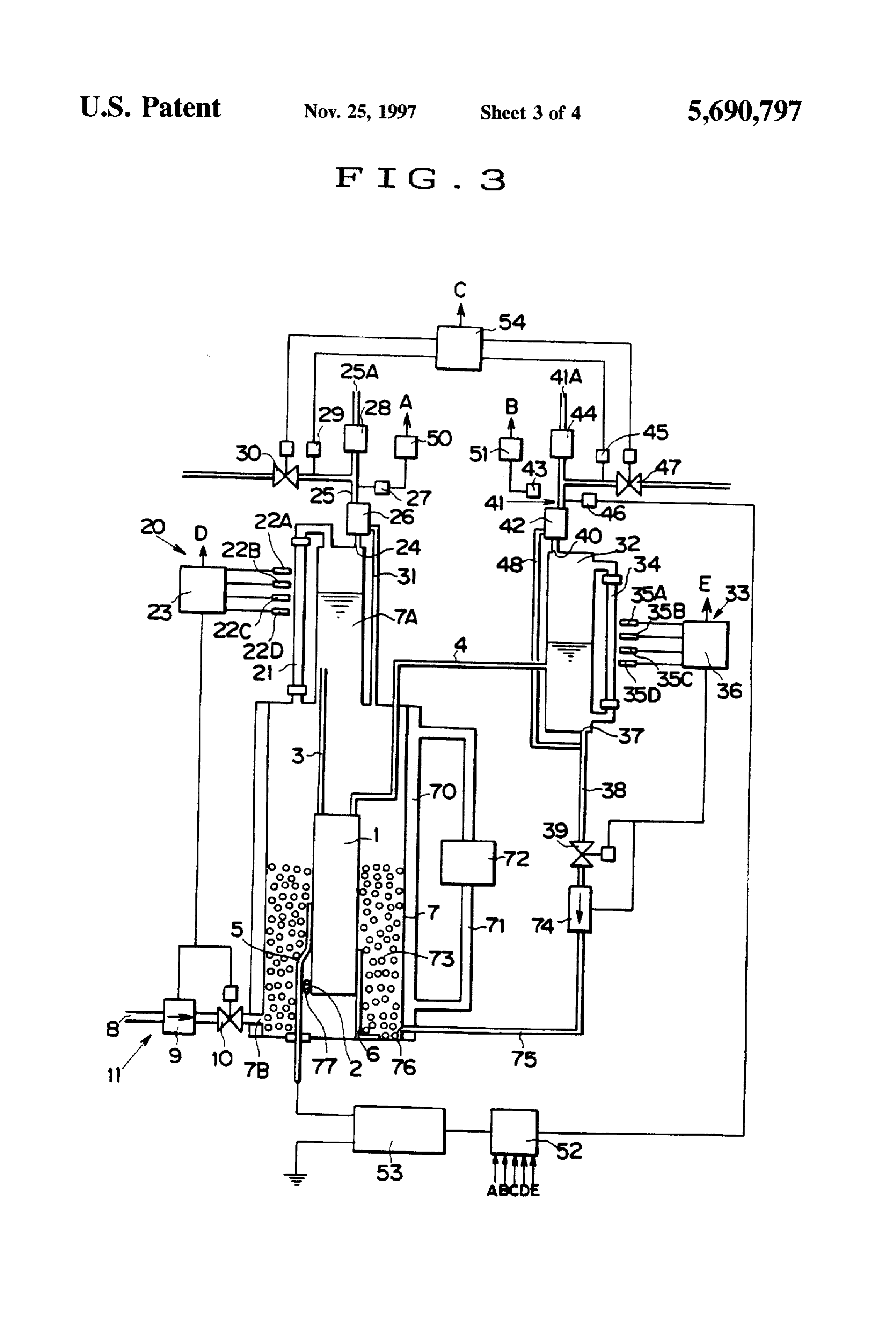
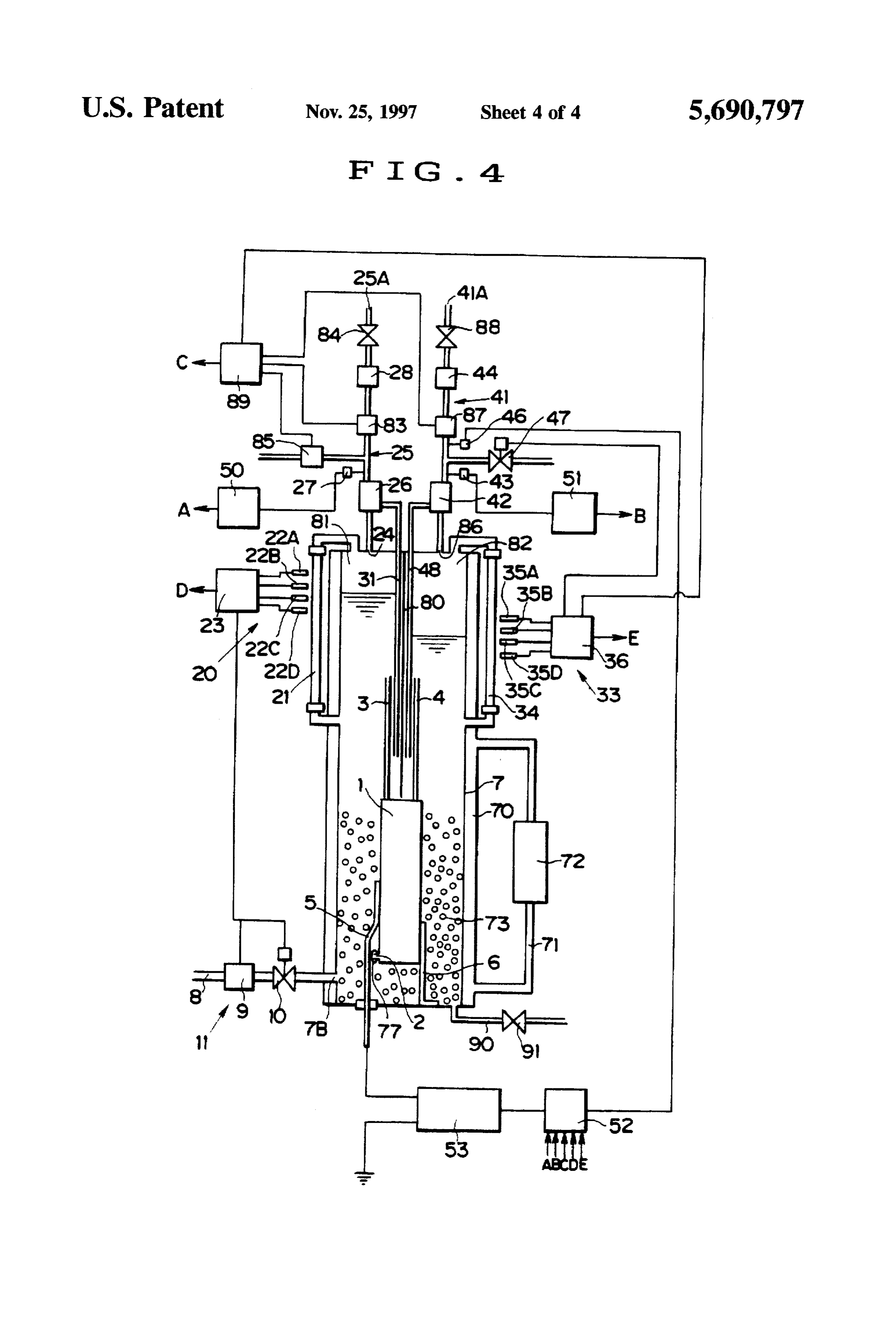
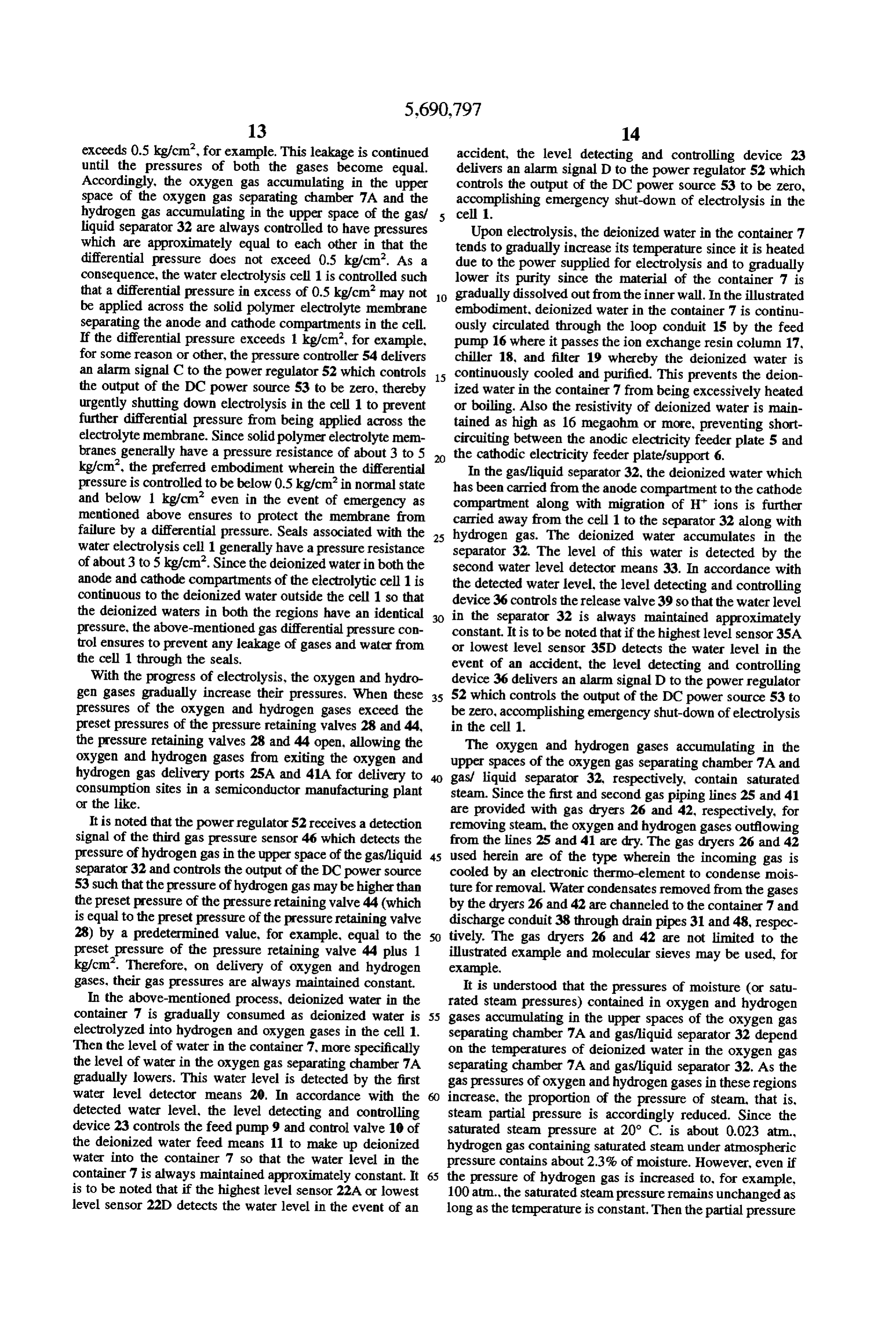
FIG. 4 is a block diagram showing a hydrogen and oxygen 15 which extends outside the container 7. Midway of the generating system according to a fourth embodiment of the loop conduit 15, a water feed pump 16, an ion exchange invention. resin column 17, a chiller 18 as a heat exchanger, and a filter DESCRIPTION OF THE PREFERRED 19 are located in the described order from the outlet 12. EMBODIMENTS At the top of the deionized water container 7 is disposed a first water level detector means 20 for detecting the level
Referring to FIG. 1, there is illustrated a hydrogen and of deionized water in the oxygen gas separating chamber oxygen gas generating system according to a first embodi 7A, that is, the surface of deionized water below oxygen gas ment of the present invention. accumulating in the chamber. This first water level detector The system includes a water electrolysis cell 1 and a 55 means 20 includes a level gauge 21, level sensors 22A to deionized water container 7 accommodating the cell 1 22D for sensing the position of water surface within the level therein. The cell 1 is to effect electrolysis of pure or gauge 21, and a level detecting and controlling device 23 deionized water into hydrogen and oxygen gases. The cell 1 electrically connected to the level sensors 22A to 22D. The includes an anode compartment, a cathode compartment and level detecting and controlling device 23 is coupled to the a diaphragm in the form of a solid polymer electrolyte deionized water feed means 11 for controlling the feed pump membrane separating the compartments from each other 9 and control valve 10 thereof. The level detecting and although the interior of the cell 1 is not shown. The cell 1 at controlling device 23 also delivers an alarm signal D to the the bottom is provided with a communication port 2 for power regulator 52.
allowing deionized water to enter the anode compartment The deionized water container 7 at its top, specifically at from the outside. At the top of the cell 1, specifically at the 65 the top of the oxygen gas separating chamber 7A is provided top of the anode compartment is connected an oxygen with an oxygen gas outlet 24. A first gas piping line 25 is outflow pipe 3 for channeling oxygen gas generated by connected to the outlet 24 for taking out oxygen gas accu
Page 11
mulating in an upper space of the oxygen gas separating At the initial state, the interior of the container 7 including chamber 7A. This first gas line 25 includes a gas dryer 26, the interior (anode and cathode compartments) of the elec a combustible gas sensor 27, and a pressure retaining valve trolytic cell 1 is filled with deionized water. In this state, a 28. The first gas line 25 further includes a first gas pressure DC voltage is applied between the anodic feeder plate 5 and detecting means in the form of a first gas pressure sensor 29 the cathodic feeder plate/support 6 by the DC power source for detecting the pressure of oxygen gas accumulating in the 53 whereby electrolysis of deionized water takes place in the upper space of the oxygen gas separating chamber 7A and a cell 1 to generate O’ and H" ions. O’ions generated in the leak valve 30. The first gas line 25 has a downstream end anode compartment are immediately converted into oxygen which forms an oxygen gas delivery port 25A for delivering gas at the anode surface. The oxygen gas in a mixed state oxygen gas to a site where oxygen gas is consumed (not 10 with deionized water moves upward through the oxygen shown). The gas dryer 26 has a drain pipe 31 connected outflow pipe 3 and enters the oxygen gas separating chamber thereto for returning removed water to the container 7. 7A. In accordance with the upward flow of oxygen gas, The hydrogen outflow pipe 4 extending from the water deionized waterflows into the electrolytic cell 1 through the electrolysis cell 1 is connected to a gas/liquid separator 32 communication port 2 so that deionized water necessary for disposed outside the container 7. The gas/liquid separator 32 15 electrolysis is replenished and at the same time, natural functions to separate hydrogen gas generated in the cathode convection of deionized water occurs in the anode compartment of the cell 1 from water. The gas/liquid sepa compartment, by which the electrolytic cell 1 is cooled. H" rator 32 is provided with a second water level detector ions generated in the anode compartment simultaneous with means 33 for detecting the level of water in the separator 32, the generation of O' ions migrate into the cathode com that is, the surface of water below hydrogen gas accumu partment through the solid polymer electrolyte membrane lating in the separator. This second water level detector under the impetus of the electric field between the anode and means 33 includes a level gauge 34, level sensors 35A to the cathode. In the cathode compartment, the H ions lose 35Dfor sensing the position of water surface within the level electric charges and form hydrogen gas. The hydrogen gas gauge 34, and a level detecting and controlling device 36 in a mixed state with entrained water is channeled through electrically connected to the level sensors 35A to 35D. The 25 the hydrogen outflow pipe 4 to the gas/liquid separator 32 gas/liquid separator 32 is provided at the bottom with a where the mixture is separated into deionized water and discharge port 37 to which is connected a discharge conduit hydrogen gas.
38 having a release valve 39. The level detecting and The oxygen gas, which is channeled together with deion controlling device 36 is coupled to the release valve 39 for ized water into the oxygen gas separating chamber 7A controlling the valve 39 for discharging water through the 30 through the oxygen outflow pipe 3, is separated from deion conduit 38. The level detecting and controlling device 36 ized water in the separating chamber 7A and collects in the also delivers an alarm signal E to the power regulator 52. upper space of the separating chamber 7A. While the The gas/liquid separator 32 at its top is provided with a pressure of oxygen gas in the upper space of the oxygen hydrogen gas outlet 40. A second gas piping line 41 is separating chamber 7A is lower than the preset pressure of connected to the outlet 40 for taking out hydrogen gas 35 the pressure retaining valve 28 in the first gas line 25, the accumulating in an upper space of the gas/liquid separator pressure retaining valve 28 is kept closed so that no oxygen 32. This second gas line 41 includes a gas dryer 42, a gas is released from the oxygen gas delivery port 25A. combustible gas sensor 43, and a pressure retaining valve Accordingly, the oxygen gas accumulating in the upper 44. The second gas line 41 further includes a second gas space of the oxygen separating chamber 7A increases its pressure detecting means in the form of a second gas pressure with the progress of electrolysis in the electrolytic pressure sensor 45 for detecting the pressure of hydrogen cell 1. On the other hand, the hydrogen gas, which is gas accumulating in the upper space of the gas/liquid channeled together with deionized water into the gas/liquid separator 32, a third gas pressure sensor 46, and a leak valve separator 32, is separated from deionized water in the 47. The second gas line 41 has a downstream end which separator 32 and collects in the upper space thereof. While forms a hydrogen gas delivery port 41A for delivering 45 the pressure of hydrogen gas in the upper space of the hydrogen gas to a site where hydrogen gas is consumed (not separator 32 is lower than the preset pressure of the pressure shown). The gas dryer 42 has a drain pipe 48 connected retaining valve 44 in the second gas line 41, the pressure thereto for flowing removed water to the discharge conduit retaining valve 44 is kept closed so that no hydrogen gas is 38. released from the hydrogen gas delivery port 41A. The combustible gas sensors 27 and 43 included in the 50 Accordingly, the hydrogen gas accumulating in the upper first and second gas lines 25 and 41 are connected to space of the separator 32 also increases its pressure with the combustible gas detectors 50 and 51, respectively. The progress of electrolysis in the electrolytic cell 1. combustible gas detectors 50 and 51 deliver alarm signals A The pressure retaining valve 28 in the first gas line 25 and and B to the power regulator 52. The first and second gas the pressure retaining valve 44 in the second gas line 41 have pressure sensors 29 and 45 of the first and second gas lines 55 preset pressures of the same value. The pressure of oxygen 25 and 41 have outputs connected to a gas pressure con gas confined in the upper space of the oxygen gas separating troller 54. The gas pressure controller 54 functions to control chamber 7A due to the pressure retaining valve 28 kept the leak valves 30 and 47 of the first and second gas lines 25 closed is detected by the first gas pressure sensor 29 whereas and 41 and delivers an alarm signal C to the power regulator the pressure of hydrogen gas confined in the upper space of 52. The power regulator 52 is thus electrically connected so the gas/liquid separator 32 due to the pressure retaining as to receive alarm signals from the gas pressure controller valve 44 kept closed is detected by the second gas pressure 54, combustible gas detectors 50, 51, and water level sensor 45. Detection signals of the gas pressure sensors 29 detecting/controlling device 23.36 and to control the power and 45 are transmitted to the gas pressure controller 54 applied from the DC source 53 to the electrolytic cell 1 in which controls the leak valves 30 and 47 such that either one response to the signals. 65 of the gases at a higher pressure is leaked through the Further referring to FIG. 1, the operation of the system corresponding one of the leak valves 30 and 47 when the according to the first embodiment is described. differential pressure between oxygen and hydrogen gases
Page 12
exceeds 0.5 kg/cm, for example. This leakage is continued accident, the level detecting and controlling device 23 until the pressures of both the gases become equal. delivers an alarm signal D to the power regulator 52 which Accordingly, the oxygen gas accumulating in the upper controls the output of the DC power source 53 to be zero, space of the oxygen gas separating chamber 7A and the accomplishing emergency shut-down of electrolysis in the hydrogen gas accumulating in the upper space of the gas/ cell 1.
liquid separator 32 are always controlled to have pressures Upon electrolysis, the deionized water in the container 7 which are approximately equal to each other in that the tends to gradually increase its temperature since it is heated differential pressure does not exceed 0.5 kg/cm. As a due to the power supplied for electrolysis and to gradually consequence, the water electrolysis cell 1 is controlled such lower its purity since the material of the container 7 is that a differential pressure in excess of 0.5 kg/cm may not 10. gradually dissolved out from the inner wall. In the illustrated be applied across the solid polymer electrolyte membrane embodiment, deionized water in the container 7 is continu separating the anode and cathode compartments in the cell. ously circulated through the loop conduit 15 by the feed If the differential pressure exceeds 1 kg/cm, for example, pump 16 where it passes the ion exchange resin column 17, for some reason or other, the pressure controller 54 delivers chiller 18, and filter 19 whereby the deionized water is an alarm signal C to the power regulator 52 which controls 15 continuously cooled and purified. This prevents the deion the output of the DC power source 53 to be zero, thereby ized water in the container 7 from being excessively heated urgently shutting down electrolysis in the cell 1 to prevent or boiling. Also the resistivity of deionized water is main further differential pressure from being applied across the tained as high as 16 megaohm or more, preventing short electrolyte membrane. Since solid polymer electrolyte mem circuiting between the anodic electricity feeder plate 5 and branes generally have a pressure resistance of about 3 to 5 the cathodic electricity feeder plate/support 6. kg/cm, the preferred embodiment wherein the differential pressure is controlled to be below 0.5 kg/cm in normal state hasInbeenthe gas/liquid separator 32, the deionized water which carried from the anode compartment to the cathode and below 1 kg/cm even in the event of emergency as compartment along with migration of H ions is further mentioned above ensures to protect the membrane from carried away from the cell 1 to the separator 32 along with failure by a differential pressure. Seals associated with the 25 hydrogen gas. The deionized water accumulates in the water electrolysis cell 1 generally have a pressure resistance separator 32. The level of this water is detected by the of about 3 to 5 kg/cm. Since the deionized water in both the second water level detector means 33. In accordance with anode and cathode compartments of the electrolytic cell 1 is the detected water level, the level detecting and controlling continuous to the deionized water outside the cell 1 so that device 36 controls the release valve 39 so that the water level the deionized waters in both the regions have an identical 30 in the separator 32 is always maintained approximately pressure, the above-mentioned gas differential pressure con trol ensures to prevent any leakage of gases and water from constant. It is to be noted that if the highest level sensor 35A or lowest level sensor 35ID detects the water level in the the cell 1 through the seals. event of an accident, the level detecting and controlling With the progress of electrolysis, the oxygen and hydro device 36 delivers an alarm signal D to the power regulator gen gases gradually increase their pressures. When these 35 52 which controls the output of the DC power source 53 to pressures of the oxygen and hydrogen gases exceed the be zero, accomplishing emergency shut-down of electrolysis preset pressures of the pressure retaining valves 28 and 44, in the cell 1.
the pressure retaining valves 28 and 44 open, allowing the The oxygen and hydrogen gases accumulating in the oxygen and hydrogen gases from exiting the oxygen and upper spaces of the oxygen gas separating chamber 7A and hydrogen gas delivery ports 25A and 41A for delivery to gas liquid separator 32, respectively, contain saturated consumption sites in a semiconductor manufacturing plant steam. Since the first and second gas piping lines 25 and 41 or the like. are provided with gas dryers 26 and 42, respectively, for It is noted that the power regulator 52 receives a detection removing steam, the oxygen and hydrogen gases outflowing signal of the third gas pressure sensor 46 which detects the from the lines 25 and 41 are dry. The gas dryers 26 and 42 pressure of hydrogen gas in the upper space of the gas/liquid 45 used herein are of the type wherein the incoming gas is separator 32 and controls the output of the DC power source cooled by an electronic thermo-element to condense mois 53 such that the pressure of hydrogen gas may be higher than ture for removal. Water condensates removed from the gases the preset pressure of the pressure retaining valve 44 (which by the dryers 26 and 42 are channeled to the container 7 and is equal to the preset pressure of the pressure retaining valve discharge conduit 38 through drain pipes 31 and 48, respec 28) by a predetermined value, for example, equal to the SO tively. The gas dryers 26 and 42 are not limited to the preset pressure of the pressure retaining valve 44 plus 1 illustrated example and molecular sieves may be used, for kg/cm. Therefore, on delivery of oxygen and hydrogen example.
gases, their gas pressures are always maintained constant. It is understood that the pressures of moisture (or satu In the above-mentioned process, deionized water in the rated steam pressures) contained in oxygen and hydrogen container 7 is gradually consumed as deionized water is 55 gases accumulating in the upper spaces of the oxygen gas electrolyzed into hydrogen and oxygen gases in the cell 1. separating chamber 7A and gas/liquid separator 32 depend Then the level of water in the container 7, more specifically on the temperatures of deionized water in the oxygen gas the level of water in the oxygen gas separating chamber 7A separating chamber 7A and gas/liquid separator 32. As the gradually lowers. This water level is detected by the first gas pressures of oxygen and hydrogen gases in these regions water level detector means 20, In accordance with the increase, the proportion of the pressure of steam, that is, detected water level, the level detecting and controlling steam partial pressure is accordingly reduced. Since the device 23 controls the feed pump 9 and control valve 10 of saturated steam pressure at 20° C. is about 0.023 atm., the deionized water feed means 11 to make up deionized hydrogen gas containing saturated steam under atmospheric water into the container 7 so that the water level in the pressure contains about 2.3% of moisture. However, even if container 7 is always maintained approximately constant. It 65 the pressure of hydrogen gas is increased to, for example, is to be noted that if the highest level sensor 22A or lowest 100 atm., the saturated steam pressure remains unchanged as level sensor 22D detects the water level in the event of an long as the temperature is constant. Then the partial pressure
Page 13
of steam is reduced to 1/100 of that under atmospheric FIG. 2 shows a hydrogen/oxygen gas generating system pressure, that is, the moisture content in hydrogen gas can be according to a second embodiment of the present invention, reduced to 1/100 of that under atmospheric pressure. This is The same elements as in the first embodiment shown in FIG. also true for oxygen gas. Therefore, it is possible to further 1 are designated by like numerals and their description is reduce the moisture content in the gas not only by providing omitted.
the gas dryers 26 and 42 as mentioned above, but also by The second embodiment of FIG. 2 is different from the establishing as high a pressure as possible relative to the first embodiment of FIG. 1 in that instead of the loop circuit pressure on intended use. The high pressure gas may be 15 shown in FIG. 1, a deionized water supply line 60 is reduced in pressure on the gas usage side. The system of the extended from the outlet 12 at the bottom of the container 7 present invention enables that the gas pressure be increased O to the communication port 2 of the electrolytic cell 1. A in practice.
More particularly, as mentioned above, the pressure of the water chiller feed pump 16, an ion exchange resin column 17, a 18 as a heat exchanger, and a filter 19 are located in oxygen gas accumulating in the upper space of the oxygen the circulation line 60.
gas separating chamber 7A and the pressure of the hydrogen In this embodiment, deionized water is pumped from the gas accumulating in the upper space of the gas/liquid 15 container 7 into the electrolytic cell 1 through the pump 16, separator 32 can be controlled so that the differential pres sure therebetween may be less than 0.5 kg/cm, for example, ion exchange column 17, chiller 18, and filter 19. Therefore deionized water which has been cooled and purified is independent of their magnitude, and therefore, the differen pumped at a constant flow rate into the cell 1 by the pump tial pressure acting across the solid polymer electrolyte 16.
membrane separating the anode and cathode compartments 20 of the water electrolysis cell 1 can also be always maintained FIG. 3 shows a hydrogen/oxygen gas generating system according below 0.5 kg/cm. Then even if the pressures of the oxygen The same elements to a third embodiment of the present invention. and hydrogen gases accumulating in the upper spaces of the as in the first embodiment shown in FIG, oxygen gas separating chamber 7A and gas/liquid separator 1 are designated by like numerals and their description is 32 are increased in magnitude, it is possible to avoid failure 25 omitted.
of the solid polymer electrolyte membrane by the differential In the embodiment of FIG. 3, the wall of the container 7 pressure in the cell 1 and to prevent any leakage of hydrogen is a hollow double wall structure which forms a water gas from the cell 1 through the seals. cooling jacket 70. A cooling water circulation line 71 is In the event of an accident wherein hydrogen gas leaks connected to the jacket 70 near its top and bottom and has into the container 7, the combustible gas detectors 50 and 51 30 a chiller 72 located midway thereof. An ion exchange resin coupled with the combustible gas sensors 27 and 43 detect 73 is received inside the container 7 and outside the elec such leakage before the explosion limit is reached and trolytic cell 1. A filter 77 is attached to the communication deliver alarm signals A and B to the power regulator 52 port 2 of the cell 1. The discharge conduit 38 connected to which controls the output of the DC power source 53 to be the discharge port 37 at the bottom of the gas/liquid sepa Zero, accomplishing emergency shut-down of electrolysis in 35 rator 32 is connected to an input side of a water feed pump the cell 1. Further leakage of hydrogen gas is thus prevented, 74 through the release valve 39. The water pump 74 has an avoiding explosion. output side connected to a return port 76 located at the The system of the first embodiment enables to increase bottom of the container 7 through a return conduit 75. It is the pressures of the oxygen and hydrogen gases to be noted that the release valve 39 and feed pump 74 are delivered to the outside for thereby reducing the moisture controlled by the water level detecting and controlling content in the oxygen and hydrogen gases. Oxygen and device 36 of the second water level detector means 33. The hydrogen gases of desirably high pressure can be generated remaining arrangement is the same as in the first embodi without a need for gas compressors. Then clean oxygen and ment shown in F.G. 1.
hydrogen gases can be delivered without contamination with In the third embodiment shown in FIG. 3, after deionized lubricant oil which would often occur when gas compressors 45 water is carried along with hydrogen gas from the electro are used. lytic cell 1 to the gas/liquid separator 32 and accumulates in It is noted that the third gas pressure sensor 46 is provided the gas/liquid separator 32, it is returned to the container 7 separately from the second gas pressure sensor 45 in the by the pump 74 through the discharge conduit 38, valve 39 illustrated embodiment. Since they are both to detect the and return conduit 75. More particularly, the water level in pressure of hydrogen gas accumulating in the upper space of 50 the gas/liquid separator 32 is detected by the second water the gas/liquid separator 32, these sensors may be combined level detector means 33. If the water level rises, the water into a single gas pressure sensor which delivers a detection level detecting and controlling device 36 controls the release signal to both the gas pressure controller 54 and the power valve 39 and feed pump 74 for returning deionized water regulator 52. from the gas/liquid separator 32 to the container 7. As a In the illustrated embodiment, deionized water in the 55 result, the water level in the gas/liquid separator 32 is container 7 is cooled and purified by means of the ion water maintained approximately constant. Since the deionized exchange resin column 17, chiller 18, and filter 19 in the which is once carried away from the electrolytic cell loop conduit 15. In order to more positively prevent the 71 in to the gas/liquid separator 32 is returned to the container this way, the amount of deionized water newly made up deionized water from being contaminated by dissolving out by the feed pump 9 through the control valve 10 is only the of the material of the container 7 from its wall, the container 7 and gas/liquid separator 32 are formed of stainless steel amount of water consumed by electrolysis. That is, it is with a passivated coating formed on at least the inner sufficient to make up substantially 1 liter of deionized water surface. It is well known that such a measure can minimize per 1 cubic meters of hydrogen gas and 0.5 cubic meters of dissolving out of the container material into deionized water. oxygen gas evolved.
Plastic materials such as PEEK may also be used to form the 65 As in the first embodiment of FIG. 1, since the hydrogen container 7 and gas/liquid separator 32 since they are least gas in the upper space of the gas/liquid separator 32 and the dissolved into deionized water. oxygen gas in the upper space of the oxygen gas separating
Page 14
chamber 7A are controlled to substantially equal pressures a hydrogen compartment 82 corresponding to the cathode with the differential pressure falling within 0.5 kg/cm, only compartment of the cell 1. The oxygen outflow pipe 3 for a minimized amount of hydrogen gas which is dissolved in channeling oxygen gas from the anode compartment of the the water returned from the gas/liquid separator 32 to the cell 1 has a distal end which opens in the oxygen compart container 7 is released in the container 7 to mix with oxygen ment 81. The hydrogen outflow pipe 4 for channeling gas in the oxygen gas separating chamber 7A. eliminating hydrogen gas from the cathode compartment of the cell 1 has the risk of producing detonating gas. Even if hydrogen gas a distal end which opens in the hydrogen compartment 82. in the water returned to the container 7 is released in the Associated with the oxygen compartment 81 of the con container 7 and hence, in the oxygen gas separating chamber 7A, it is discharged outside along with oxygen gas through O atainerlevel 7 is the first water level detector means 20 including gauge 21 as in the foregoing embodiments. Similarly oxygen gas delivery port 25A or leak valve 30, eliminating associated with the hydrogen compartment 82 of the con the risk that hydrogen gas accumulates in the container 7 to tainer 7 is the second water level detector means 33 includ a sufficiently high concentration to form detonating gas. ing a level gauge 34. The second water level detector means Since the container 7 is loaded with the ion exchange resin 33 is of the same arrangement as that associated with the 73 in the embodiment of FIG. 3, the deionized water in the 15 gas/liquid separator 32 in the foregoing embodiments. The container 7 is maintained in a continuously purified state. container 7 has a water cooling jacket which is the same as The filter 77 at the communication port 2 of the electrolytic in the third embodiment of PIG. 3. A drain pipe 90 is cell 1 prevents the ion exchange resin 73 from entering the connected to the container 7 at its bottom and has a manual anode compartment of the cell. drain valve 91 associated therewith, The water cooling jacket 70 surrounds the wall of the 20 The first gas piping line 25 is connected to the oxygen gas container 7. Coolant water is circulated through the jacket 70 outlet 24 at the top of the oxygen compartment 81 of the while being cooled by the chiller 72. Heat generated by container 7 and has a gas dryer 26, a combustible gas sensor electrolysis in the electrolytic cell 1 is removed by the 27, and a pressure retaining valve 28 as in the foregoing coolant waterflowing through the jacket 70, preventing the 25 embodiments. In a main section of the first gas piping line cell 1 from reaching an abnormally high temperature. Where 25 extending to the oxygen gas delivery port 25A, a flow rate the system is designed to generate small amounts of gases, controller 83 and a manual valve 84 are provided on the amount of heat generated is also small. Then instead of opposite sides of the pressure retaining valve 28. A flow rate water cooling, air cooling with a forced flow of cold air is controller 85 is provided in a leakage branch of the first gas sufficient and sometimes, natural heat dissipation is satis piping line 25.
factory. Disposed at the top of the hydrogen compartment 82 in It is noted that although the hydrogen gas in the gas/liquid the container 7 is a hydrogen gas outlet 86 to which a second separator 32 and the oxygen gas in the oxygen gas separating gas piping line 41 is connected for channeling hydrogen gas chamber 7A are controlled to substantially equal pressures in to the hydrogen gas delivery port 41A. The second gas the illustrated embodiments, the control program of the gas piping line 41 has a gas dryer 42, a combustible gas sensor pressure controller 54 may be altered so that the pressure of 35 43, and a pressure retaining valve 44, a third gas pressure hydrogen gas in the gas/liquid separator 32 is always slightly sensor 46, a leak valve 47 as in the foregoing embodiments. higher than the pressure of oxygen gas in the oxygen gas In a main section of the second gas piping line 41 extending separating chamber 7A (for example, by about 0.5 kg/mm). to the hydrogen gas delivery port 41A, a flow meter 87 and This differential pressure can force the water accumulating a manual valve 88 are provided on opposite sides of the in the gas/liquid separator 32 back into the container 7 pressure retaining valve 44. It is noted that the drain conduits through the discharge conduit 38 and return conduit 75. 31 and 48 connected to the gas dryers 26 and 42 are extended Then the feed pump 74 may be replaced by an openable deeply into the oxygen and hydrogen compartments 81 and valve and/or a check valve having no pumping action. 82 of the container 7, respectively.
Where an openable valve is used, it may be controlled in 45 The flow meter 87 and the water level detecting and accordance with the water level in the gas/liquid separator controlling device 36 of the second water level detector 32 detected by the second water level detector means 33. As means 33 have outputs connected to a gas flow rate control is evident from the foregoing description, the difference in unit 89 which has outputs connected to the flow rate con pressure between the hydrogen gas in the gas/liquid sepa trollers 83 and 85 for controlling them. rator 32 and the oxygen gas in the oxygen gas separating 50 chamber 7A should be suppressed to less than about 1 hydrogenfourth In the gases embodiment shown in FIG. 4, oxygen and generated in the electrolytic cell 1 are kg/cm, for example, so that a significant differential pres sure may not act across the electrolyte membrane in the 3channeled through the oxygen and hydrogen outflow pipes and 4 and accumulate in the upper spaces of the oxygen electrolytic cell 1.
and hydrogen compartments 81 and 82, respectively. Since
In the foregoing embodiments, separation of water from 55 hydrogen gas generated in the electrolytic cell 1 is carried the oxygen and hydrogen compartments 81 and 82 are out in the gas/liquid separator 32 separate from the container oxygen andby hydrogen separated the partition 80, no mixing occurs between gases. In a lower portion of the 7. In some cases, the gas/liquid separator 32 may be omitted, container 7, on the other hand, deionized water is continuous and separation of water from hydrogen gas can also be between the oxygen and hydrogen compartments 81 and 82. carried out within the electrolytic cell 1. This is illustrated in Then the oxygen gas accumulating in the upper space of the FIG. 4 as a fourth embodiment. oxygen compartment 81 and the hydrogen gas accumulating In the embodiment of FIG. 4, the electrolytic cell 1 is in the upper space of the hydrogen compartment 82 are accommodated in the container 7 as in the foregoing always kept at the same pressure. Therefore, no differential embodiments. Above the electrolytic cell 1, the interior of pressure is applied across the diaphragm or solid polymer the container 7 is divided and partitioned by a central 65 electrolyte membrane separating the anode and the cathode partition 80 into two compartments, an oxygen compartment in the electrolytic cell 1, the electrolyte membrane being free 81 corresponding to the anode compartment of the cell 1 and of failure by a differential pressure. Since the pressures in the
Page 15
anode and cathode compartments in the cell 1 and the controller 83 in the first gas piping line 25 does not reach the pressure of deionized water outside the cell 1 are also always set value of flow rate although the flow rate controller 83 is maintained equal, the differential pressure applied across the fully opened, a flow rate corresponding to the difference seals in the cell 1 is also zero. There is no risk of failure of between the set value of flow rate and the actual flow rate of the seals by a differential pressure and hence, no risk of oxygen gas is set in the flow rate controller 85 on the leakage leakage of hydrogen and oxygen gases from the cell 1 into branch. Then oxygen gas is leaked through the flow rate the container 7. controller 85 at a flow rate corresponding to the difference The hydrogen and oxygen gas generating system accord between the set value of flow rate in the flow rate controller ing to the fourth embodiment of the invention is started by 83 and the actual flow rate of oxygen gas. As a result, the first manually opening the flow rate controller 85 and leak 10 sum of the flow rate of oxygen gas delivered to the external valve 47, manually opening the control valve 10 of the destination from the oxygen gas delivery port 25A through deionized water feed means 11, and actuating the feed pump the flow rate controller 83 in the first gas piping line 25 and 9 to pump deionized water into the container 7 until it is the flow rate of oxygen gas leaked through the flow rate completely full of deionized water. During pumping, the controller 85 in the same first gas piping line 25 is one half levels of water in the oxygen and hydrogen compartments 15 of the flow rate of hydrogen gas delivered to the external 81 and 82 of the container 7 are visually monitored by way destination through the second gas piping line 41. As a of the level gauge 21 of the first water level detector means whole, the flow rate of hydrogen gas and the flow rate of 20 and the level gauge 34 of the second water level detector oxygen gas are maintained at a ratio of 2:1. means 33. It is to be noted that even when the components are At this point, the manual valves 84, 88, flow rate con controlled to achieve the desired flow rate ratio of hydrogen troller 85, leak valve 47, and water feed control valve 10 are to oxygen gas as mentioned above, an actual process closed, and the pump 9 is interrupted. In this state, electric encounters considerable errors, failing to correctly maintain power is supplied from the DC power source 53 to the the flow rateratio at 2:1. In such a situation, either one of the electrolytic cell 1 for effecting electrolysis of deionized water levels in the oxygen and hydrogen compartments 81 water for generating oxygen and hydrogen gases. Oxygen 25 and 82 of the container 7 is above the water level for normal and hydrogen gases are channeled to the oxygen and hydro operation and the other is below the water level for normal gen compartments 81 and 82 to establish gas pressures operation. Then in the fourth embodiment of FIG. 4, the therein. The pressure of hydrogen gas is detected by the gas water level in the hydrogen compartment 82 is detected by pressure sensor 46. Since the container 7 is completely full the level sensor 35A to 35D of the second water level of deionized water in the initial state, the hydrogen gas 30 detector means 33. If the water level in the hydrogen pressure rapidly increases and immediately reaches the compartment 82 is below the normal level, the water level preset pressure value. Then the gas pressure sensor 46 detecting and controlling device 36 delivers a signal to the produces a pressure signal to the power regulator 52 to gasflow rate controller 89 which functions to reduce the set interrupt the DC power source 53. value of flow rate of the flow rate controller 83 or 85 in the In this state, the manual drain valve 91 is slightly opened first gas piping line 25, thereby reducing the total flow rate
to allow the deionized water in the container 7 to be forcibly of oxygen gas. Inversely, if the water level in the hydrogen discharged into the drain conduit 90. Then the water levels compartment 82 is above the normal level, the water level in the oxygen and hydrogen compartments 81 and 82 lower detecting and controlling device 36 delivers a signal to the and accordingly, the pressures in the oxygen and hydrogen gas flow rate controller 89 which functions to increase the compartments 81 and 82 lower. The gas pressure sensor 46 set value of flow rate of the flow rate controller 83 or 85, and power regulator 52 then function to restart electric thereby increasing the total flow rate of oxygen gas. As a power supply from the DC power source 53 to the electro result of continuously controlling the water levels substan lytic cell 1 for restarting electrolysis of deionized water to tially constant, the ratio in flow rate of hydrogen gas to generate oxygen and hydrogen gases again. As a oxygen gas is correctly controlled at 2:1.
consequence, deionized water in the container 7 is further 45 On the other hand, the water level in the oxygen com displaced and discharged through the drain conduit 90 and partment 81 of the container 7 is detected by the level sensor the water levels in the oxygen and hydrogen compartments 22A to 22D of the first water level detector means 20. In 81 and 82 lower further. When the water levels in the oxygen accordance with the detected water level, the water level and hydrogen compartments 81 and 82 reach the predeter detecting and controlling device 23 controls the pump 9 and mined levels (water levels for normal operation) in this way, the control valve 10 of the deionized water feed means 11. the manual drain valve 91 is closed to prohibit further If the water level in the oxygen compartment 81 is below the lowering of the water levels. The pressure of oxygen gas in normal level, deionized water is pumped into the container the oxygen compartment 81 and the pressure of hydrogen 7. Accordingly, deionized water is timely made up in the gas in the hydrogen compartment 82 increase and reach the amount of deionized water consumed by electrolysis and predetermined pressure values whereupon electrolysis of 55 hydrogen and oxygen gases can be delivered under the deionized water is interrupted. Then the manual valves 88 desired pressures.
and 84 are opened to deliver hydrogen and oxygen gases to In the foregoing description of the fourth embodiment external destinations through the hydrogen and oxygen gas shown in FIG. 4, the flow rate of oxygen gas is controlled by delivery ports 41A and 25A, respectively. controlling the flow rate controller 83 or 85 of the first gas The flow rate of hydrogen gas delivered to the external piping line 25 in accordance with the water level in the destination is measured by the flow meter 87 in the second hydrogen compartment 82 detected by the second water gas piping line 41 and based on that measurement, the gas level detector means 33, and the pumping of deionized water flow rate control unit 89 controls the flow rate controller 83 is controlled by controlling the deionized water feed means such that the flow rate of the flow rate controller 83 in the 11 in accordance with the water level in the oxygen com first gas piping line 25 (that is, flow rate of oxygen gas) may 65 partment 81 detected by the first water level detector means be set at one half of the flow rate of hydrogen gas. If the 20. Inversely, it is acceptable in some cases that the pumping actual flow rate of oxygen gas flowing through the flow rate of deionized water is controlled by controlling the deionized
Page 16
water feed means 11 in accordance with the water level in oxygen gas generating system according to the invention can the hydrogen compartment 82 detected by the second water deliver hydrogen and oxygen gases to destinations of use in level detector means 33, and the flow rate of oxygen gas is a stable safe manner as needed without a need for trans controlled by controlling the flow rate controller 83 or 85 of porting or storing high pressure gases because the system the first gas piping line 25 in accordance with the water level 5 can be located near the destinations of use. in the oxygen compartment 81 detected by the first water We claim:
level detector means 20. 1. A hydrogen and oxygen gas generating system com Although in the foregoing embodiments, the DC power prising source 53 is controlled by the power regulator 52 in accor a water electrolysis cell having anode and cathode com dance with the pressure of hydrogen gas by providing the 10 partments separated from one another by a diaphragm third gas pressure sensor 46 in the hydrogen gas flowpath or wherein deionized water is electrolyzed to generate second gas piping line 41, it is acceptable in some cases that oxygen and hydrogen gases in the anode and cathode the DC power source 53 is controlled by the power regulator compartments, respectively, 52 in accordance with the pressure of oxygen gas by an oxygen outflow pipe connected to the anode compart providing the third gas pressure sensor 46 in the first gas 15 ment of said electrolytic cell for channeling oxygen gas piping line 25. resulting from electrolysis upward from the anode compartment,
In the fourth embodiment of FIG. 4, the container 7 has a water cooling jacket structure and is loaded with the ion a hydrogen outflow pipe connected to the cathode com exchange resin 73 as in the third embodiment of FIG. 3. partment of said electrolytic cell for channeling hydro Instead, the fourth embodiment of FIG. 4 may employ a loop 20 gen gas resulting from electrolysis outward from the circuit arrangement as in the first embodiment of FIG. 1. cathode compartment,
That is, a loop circuit 15 having a pump 16, ion exchange a container which can be filled with deionized water, resin column 17, heat exchanging chiller 18, and filter 19 surrounding the electrolytic cell and supporting the cell incorporated therein may be provided for achieving cooling 25 submerged in deionized water, said container including and purifying of deionized water within the loop circuit 15. an upper portion defining an oxygen gas separating Alternatively, the fourth embodiment of FIG. 4 may employ chamber where an upper end of said oxygen outflow an arrangement as in the second embodiment of FIG. 2. That pipe opens, is, a deionized water circulation line 60 may be extended a deionized water feed means for feeding deionized water from the outlet 12 at the bottom of the container 7 to the into said container, communication port 2 of the electrolytic cell 1. and a water 30 said cell further having a communication port at the feed pump 16, an ion exchange resin column 17, heat bottom of the anode compartment for communication exchanging chiller 18, and a filter 19 be incorporated in the of deionized water between the cell interior and the circulation line 60 whereby cooled and purified water is container interior, pumped from the container 7 into the electrolytic cell 1 35 a gas/liquid separator disposed outside said container and through the circulation line 60. connected to the cathode compartment of said electro In the foregoing embodiments, the oxygen gas separating lytic cell through the hydrogen outflow pipe for receiv chamber 7A is provided above the container 7 as an upper ing hydrogen gas, portion thereof. Like the gas/liquid separator 32 for hydro a first gas pressure detecting means for detecting the gen gas, the oxygen gas separating chamber may be pro pressure of oxygen gas accumulating in an upper space vided separately from the container 7. In this case, the of said oxygen gas separating chamber, oxygen gas outlet pipe 3 is extended outside the container 7 a second gas pressure detecting means for detecting the and connected to the oxygen gas separating chamber in the pressure of hydrogen gas accumulating in an upper form of a gas/liquid separator. The discharge pipe may be space of said gas/liquid separator, directly connected to the container without an intervening 45 a first gas piping line for delivering outward the oxygen valve. gas accumulating in an upper space of said oxygen gas In the foregoing description, the structure of the water separating chamber, electrolysis cell is not specified because any of well-known a second gas piping line for delivering outward the cell structures for water electrolysis may be used. Useful hydrogen gas accumulating in an upper space of said cells cover from a cell of simple structure using a single SO gas/liquid separator, solid electrolyte membrane as a diaphragm to a cell of a gas pressure control means for controlling said first and multilayer structure using a stack of several hundred solid second gas piping lines in accordance with the values electrolyte membranes as a diaphragm. of gas pressure detected by said first and second gas The hydrogen and oxygen gas generating system accord pressure detecting means, to control the pressure of ing to the invention can increase the pressures of hydrogen 55 oxygen gas accumulating in an upper space of said and oxygen gases, minimize the differential pressure applied oxygen gas separating chamber and the pressure of across the diaphragm, typically solid polymer electrolyte hydrogen gas accumulating in an upper space of said membrane, separating the anode and cathode compartments gas/liquid separator, of the electrolytic cell, prevent failure of the diaphragm a DC power source for supplying electric power to said which is vulnerable to pressure, prevent leakage of gas from electrolytic cell, and the cell through seals, and therefore deliver hydrogen and a power regulator coupled to said DC power source for oxygen gases under desirably high pressures without a need controlling the power supply to said electrolytic cell to for gas compressors. The increased pressures of hydrogen control the pressure of hydrogen gas and the pressure of and oxygen gases lead to additional advantages that the oxygen gas.
partial pressure of moisture as an impurity in the respective 65 2. The system of claim 1 further comprising gases can be suppressed relatively low and the respective a first level detector means for detecting the level of water gases are available at higher purity. The hydrogen and in said oxygen gas separating chamber, and
Page 17
means for actuating said deionized water feed means to fluid tight manner to prevent any gas leakage feed deionized water into said container in accordance therebetween, upper ends of said oxygen and hydrogen with the water level in the oxygen gas separating outflow pipes opening in said oxygen and hydrogen chamber detected by said first level detector means. compartments, respectively, 3. The system of claim 1 further comprising a deionized water feed means for feeding deionized water a second level detector means for detecting the level of into said container, water in said gas/liquid separator, and said cell further having a communication port at the means for discharging water accumulated in said gas/ bottom of the anode compartment for communication liquid separator in accordance with the water level in of deionized water between the cell interior and the said gas/liquid separator detected by said second level 10 container interior, detector means.
4. The system of claim 1 further comprising a first level detector means for detecting the level of water in said oxygen compartment, a second level detector means for detecting the level of a second level detector means for detecting the level of water in said gas/liquid separator, 15 water in said hydrogen compartment, a discharge conduit connected between said gas/liquid separator and said container for discharging water a first gas piping line for delivering outward the oxygen accumulated in said gas/liquid separator therethrough, gas accumulating in an upper space of said oxygen a pump disposed in said discharge conduit for pumping compartment, said first gas piping line having one flow water from said gas/liquid separator to said container, controller for controlling the flow rate of outward and oxygen gas flow and said first gas piping line including means for actuating said pump in accordance with the a branch for leaking oxygen gas and another flow water level in said gas/liquid separator detected by said controller in the branch for controlling the flow rate of second level detector means. leaking oxygen gas flow, 5. The system of claim 1 further comprising 25 a second gas piping line for delivering outward the a second level detector means for detecting the level of hydrogen gas accumulating in an upper space of said water in said gas/liquid separator, hydrogen compartment, said second gas piping line a discharge conduit connected between said gas/liquid having a flow meter for measuring the flow rate of separator and said container for discharging water 30 hydrogen gas, accumulated in said gas/liquid separator therethrough, a gas flow rate control means for controlling at least one a valve disposed in said discharge conduit, and of the flow controllers of said first gas piping line in means for opening and closing said valve in accordance accordance With a measurement of the flow meter of with the water level in said gas/liquid separator said second gas piping line and controlling the other detected by said second level detector means, 35 flow controller in the branch of said first gas piping line said gas pressure control means functioning such that the in accordance with the water level detected by said pressure of hydrogen gas accumulating in an upper second or first level detector means, space of said gas/liquid separator may be higher than said deionized water feed means being actuated to feed the pressure of oxygen gas accumulating in an upper deionized water into said container in accordance with space of said oxygen gas separating chamber. the water level detected by said first or second level 6. The system of claim 1 wherein said gas pressure control detector means, means functions such that the difference between the pres a DC power source for supplying electric power to said sure of oxygen gas accumulating in an upper space of said electrolytic cell, and oxygen gas separating chamber and the pressure of hydro 45 a power regulator coupled to said DC power source for gen gas accumulating in an upper space of said gas/liquid separator may fall within a predetermined range. controlling the power supply to said electrolytic cell in 7. A hydrogen and oxygen gas generating system com accordance with the pressure detected by a gas pressure prising detecting means in said second or first gas piping line a water electrolysis cell having anode and cathode com 50 to control the gas pressure.
partments separated from one another by a diaphragm 8. The system of claim 1 or 7 wherein said gas flow rate wherein deionized water is electrolyzed to generate control means controls such that the total flow rate of oxygen oxygen and hydrogen gases in the anode and cathode gas through the one and other flow controllers of said first compartments, respectively, gas piping line may be one half of the flow rate of hydrogen an oxygen outflow pipe connected to the anode compart 55 gas through said second gas piping line. ment of said electrolytic cell for channeling oxygen gas 9. The system of claim 1 or 7 further comprising a loop resulting from electrolysis upward from the anode connected to said container and having a pump, a heat compartment, exchanger, an ion exchanger, and a filter arranged in series a hydrogen outflow pipe connected to the cathode com for circulating deionized water between said container and partment of said electrolytic cell for channeling hydro the loop.
gen gas resulting from electrolysis upward from the 10. The system of claim 1 or 7 further comprising a cathode compartment, deionized water supply line connected to an outlet port of a container which can be filled with deionized water, said container and the communication port of said electro surrounding the electrolytic cell and supporting the cell lytic cell and having a pump, a heat exchanger, an ion submerged in deionized water, said container including 65 exchanger, and a filter arranged in series for supplying a partition for dividing an upper portion of said con deionized water from said container to said cell through the tainer into oxygen and hydrogen compartments in a supply line.
Page 18
11. The system of claim 1 or 7 further comprising a 13. The system of claim 1 or 7 wherein said container is cooling means embracing said container for cooling said loaded with an ion exchange resin. container with coolant. 14. The system of claim 1 or 7 wherein at least one of said first and second gas piping lines includes a gas dryer.
12. The system of claim 1 or 7 wherein each of said first 5 15. The system of claim 1 or 7 wherein said diaphragm is and second gas piping lines includes a pressure retaining a membrane of a solid polymer electrolyte. means which opens to allow gas flow when the applied 16. The system of claim 1 or 7 wherein said container is pressure is not lower than a preset value and closes to on made of stainless steel with a passivated oxide film formed the inner surface thereof.
prevent gas flow when the applied pressure is lower than the preset value. sk k k k :
Provenance
- Collection
- Cited prior art
- Original PDF
- patentimages.storage.googleapis.com →
- Filed
- 1996-01-18
- Pages
- 18
- Method
- pdftotext (the PDF's own text layer) + pdftoppm 300dpi page scans
- Source
- Google Patents bibliographic record
- Granted
- 1997-11-25
- Inventors
- Hiroyuki Harada; Takashi Sasaki; Kiyoshi Hirai; Shinichi Yasui; Hiroko Kobayashi; Mamoru Nagao; Mitsubishi Corp; Shinko Pantec Co Ltd
- Transcribed from
- patentimages.storage.googleapis.com →