patent · US5012771
Intake system for multi-cylinder engine
7 May 1991
Page 1 — bibliographic record
United States Patent (19) (11) Patent Number: 5,012,771 Oda et al. (45) Date of Patent: May 7, 1991 54 INTAKE SYSTEM FOR MULTI-CYLINDER FOREIGN PATENT DOCUMENTS
ENGINE
75 Inventors: Hiroyuki Oda, Hiroshima; 60-14169 4/1985 Japan. Toshimitsu Tanaka, Yamaguchi; 01 17920 5/1989 Japan ................................ 123/52 M Naoyuki Yamagata; Kazuhiko 0l 17921 5/1989 Japan ................................ 123/52 M Hashimoto, both of Hiroshima, all of
Japan Primary Examiner-David A. Okonsky
Attorney, Agent, or Firm-Fleit, Jacobson, Cohn, Price,
Holman & Stern 73 Assignee: Mazda Motor Corporation,
Hiroshima, Japan 57 ABSTRACT
An intake system is incorporated in a multi-cylinder 21 Appl. No.: 485,876 internal combustion engine having a plurality of cylin ders. The intake system includes an intake manifold 22 Filed: Feb. 28, 1990 having a plurality of discrete intake passages connected to the plurality of cylinders, respectively, and two in 30 Foreign Application Priority Data take pipes, each intake pipe being arranged in such a way as to descend substantially vertically downwardly
Feb. 28, 1989 JP Japan .................................... - 49392 from a communicating portion where the intake pipe communicates with each of two groups of the intake 51) int. Cl. ............................................. FO2M 35/10 passages, turns to extend horizontally in one longitudi 52 U.S. Cl. ......................... 123/52 MB; 123/52 MC nal direction of the engine body and then turns back to (58) Field of Search ......... 123/52 M., 52 MB, 52 MC, extend in the opposite longitudinal direction of the en 123/52 MF, 52 ML, 52 MV gine body surrounding the discrete intake passages. The two groups of the discrete intake passages are con (56) References Cited nected to two groups of the cylinders which in each and the same group are not intended to be fired one after
6 Claims, 8 Drawing Sheets
Page 2
Drawing sheet — no readable text.
Page 3
Drawing sheet — no readable text.
Page 4
Drawing sheet — no readable text.
Page 5
Drawing sheet — no readable text.
Page 6
Drawing sheet — no readable text.
Page 7
Drawing sheet — no readable text.
Page 8
Drawing sheet — no readable text.
Page 9
Drawing sheet — no readable text.
Page 10
the same group are not intended to be fired one after
NTAKE SYSTEM FOR MULTI-CYLNDER another.
ENGINE The two communicating portions are preferably dis posed laterally to the engine body and arranged hori
FIELD OF THE INVENTION zontally side by side, thereby laying the two intake The present invention relates to an intake system for ifpipes in parallel with each other. The intake pipe may, a multi-cylinder engine, and more particularly to an tion portion.descend downwardly from the communica desirable, intake system for a multi-cylinder engine in which an The arrangement of the intake pipes surrounding the intake collecting pipe communicating with discrete O discrete intake passages allows to incorporate suffi intake pipes of an intake manifold is lengthened as long ciently long intake pipes without making the intake as possible, thereby swelling resonance effects so as to system bulky.
increase output torque of the multi-cylinder engine at low engine speeds. BRIEF DESCRIPTION OF THE DRAWINGS BACKGROUND OF THE INVENTION 15 Still other aspects of the present invention and more specific features will become apparent to those having
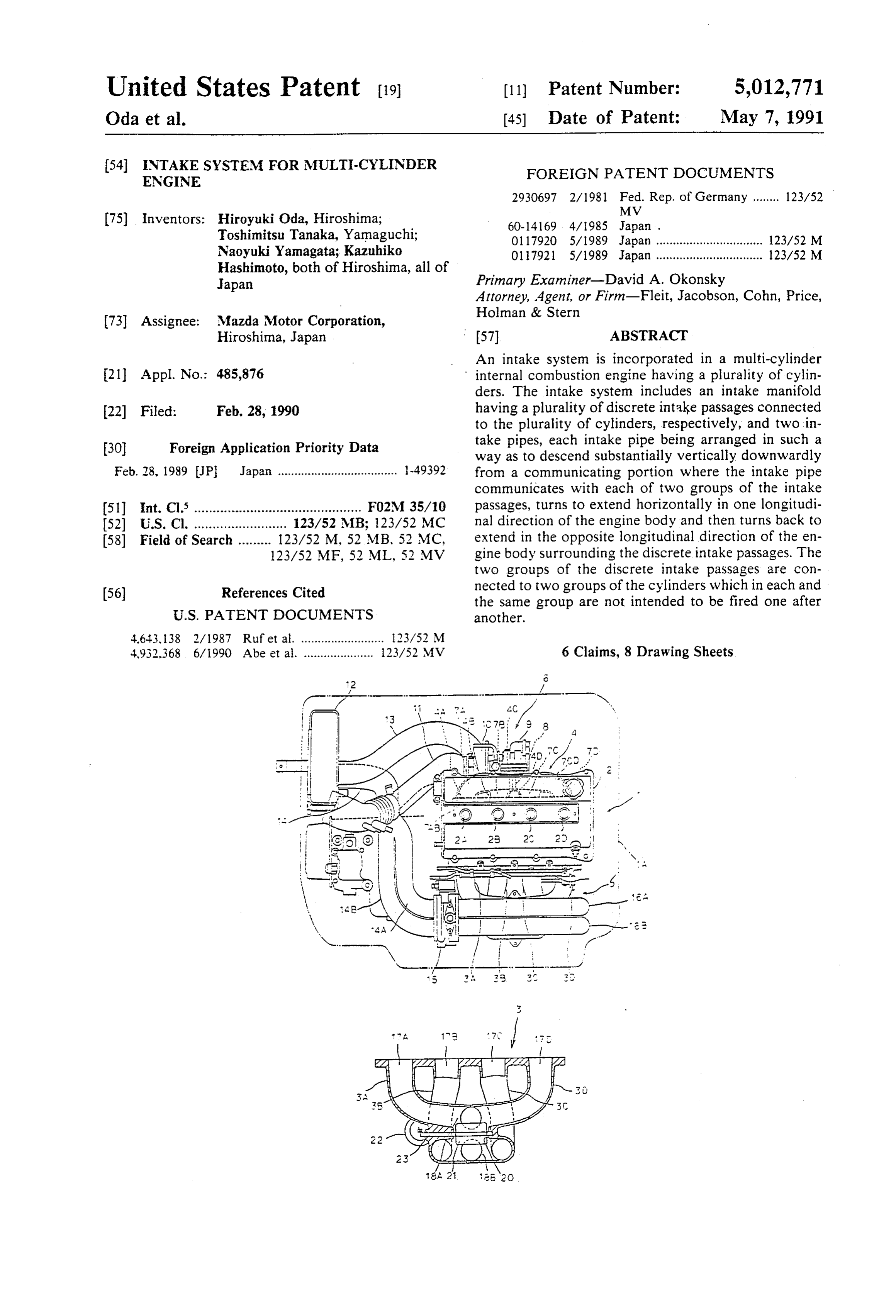
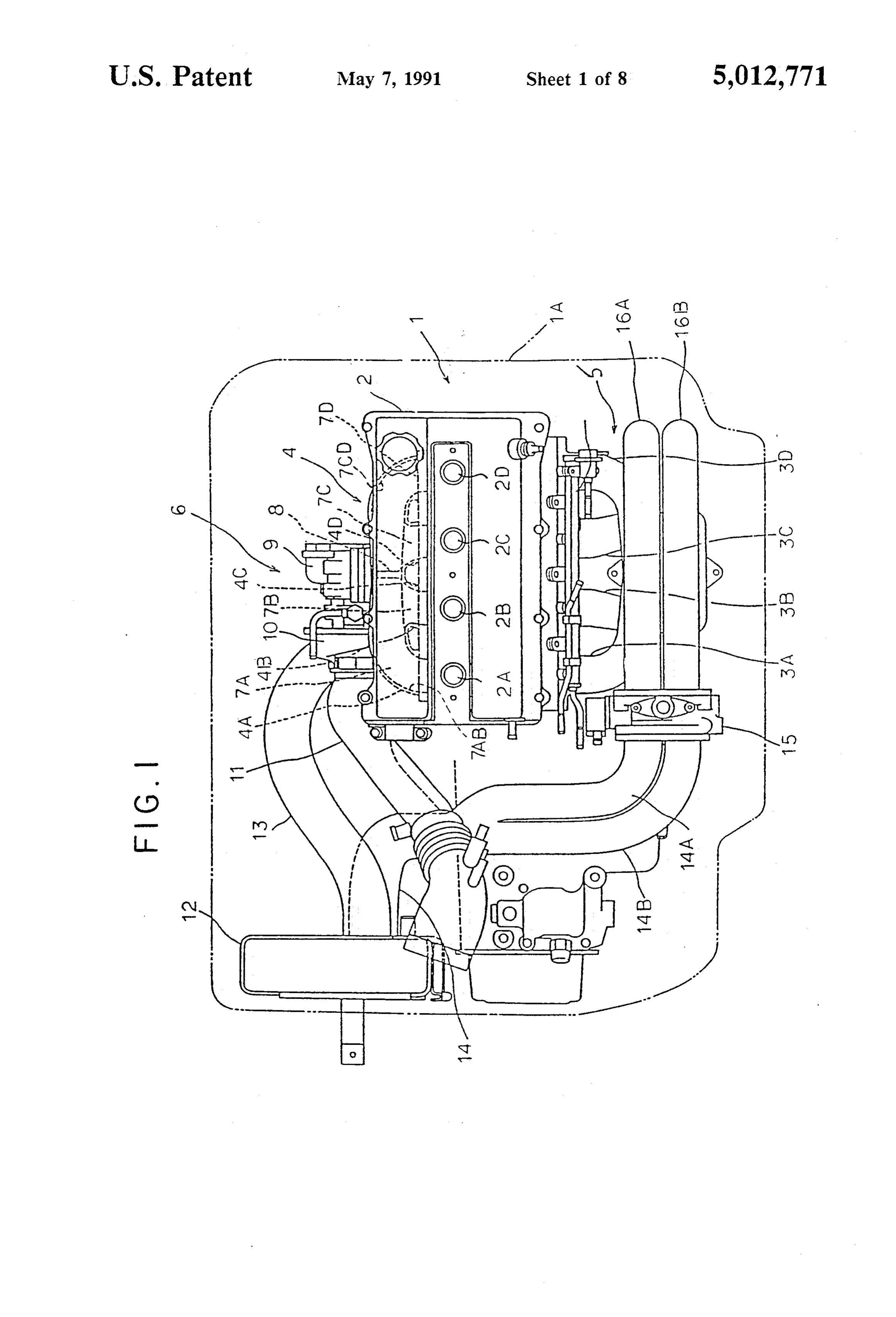
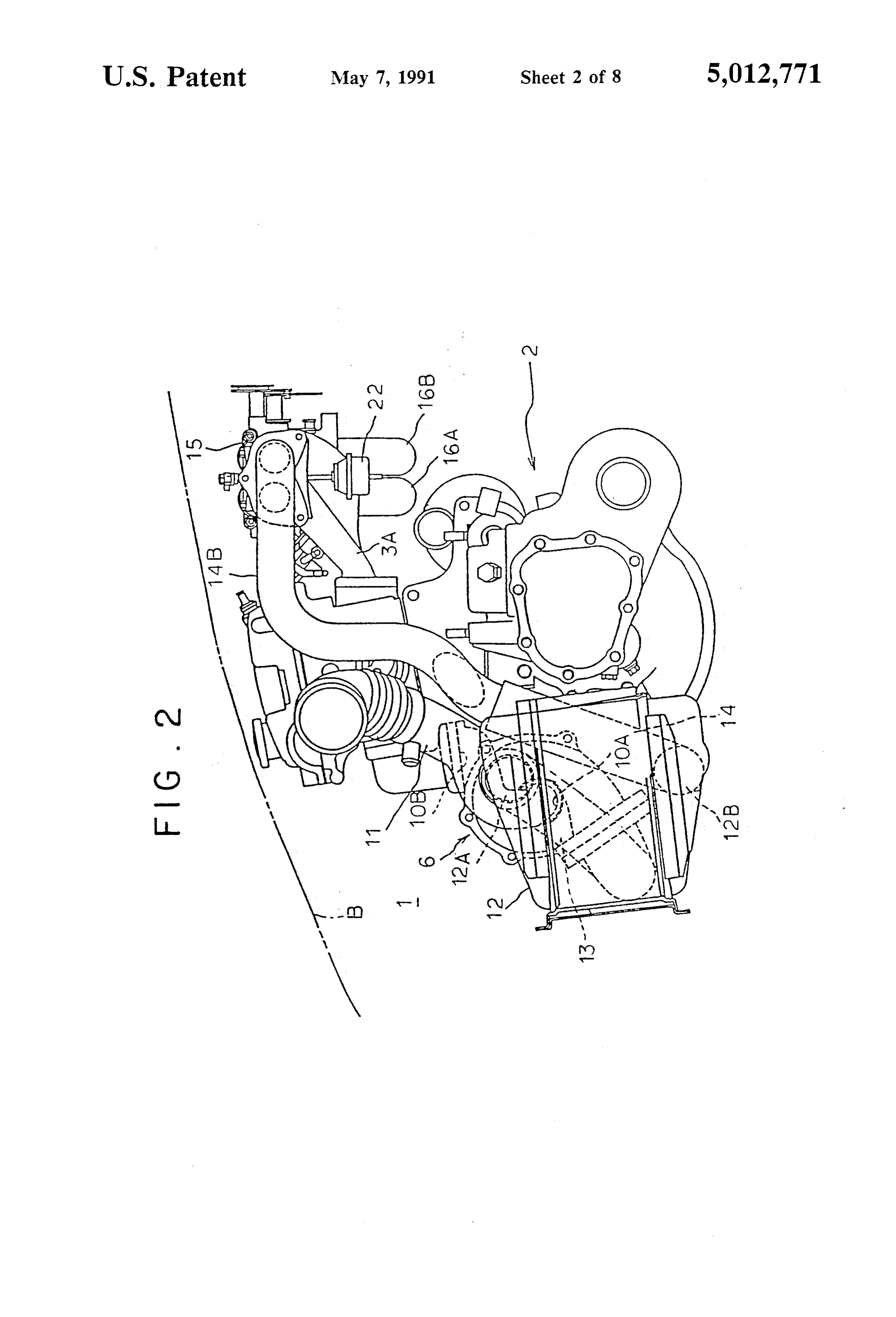
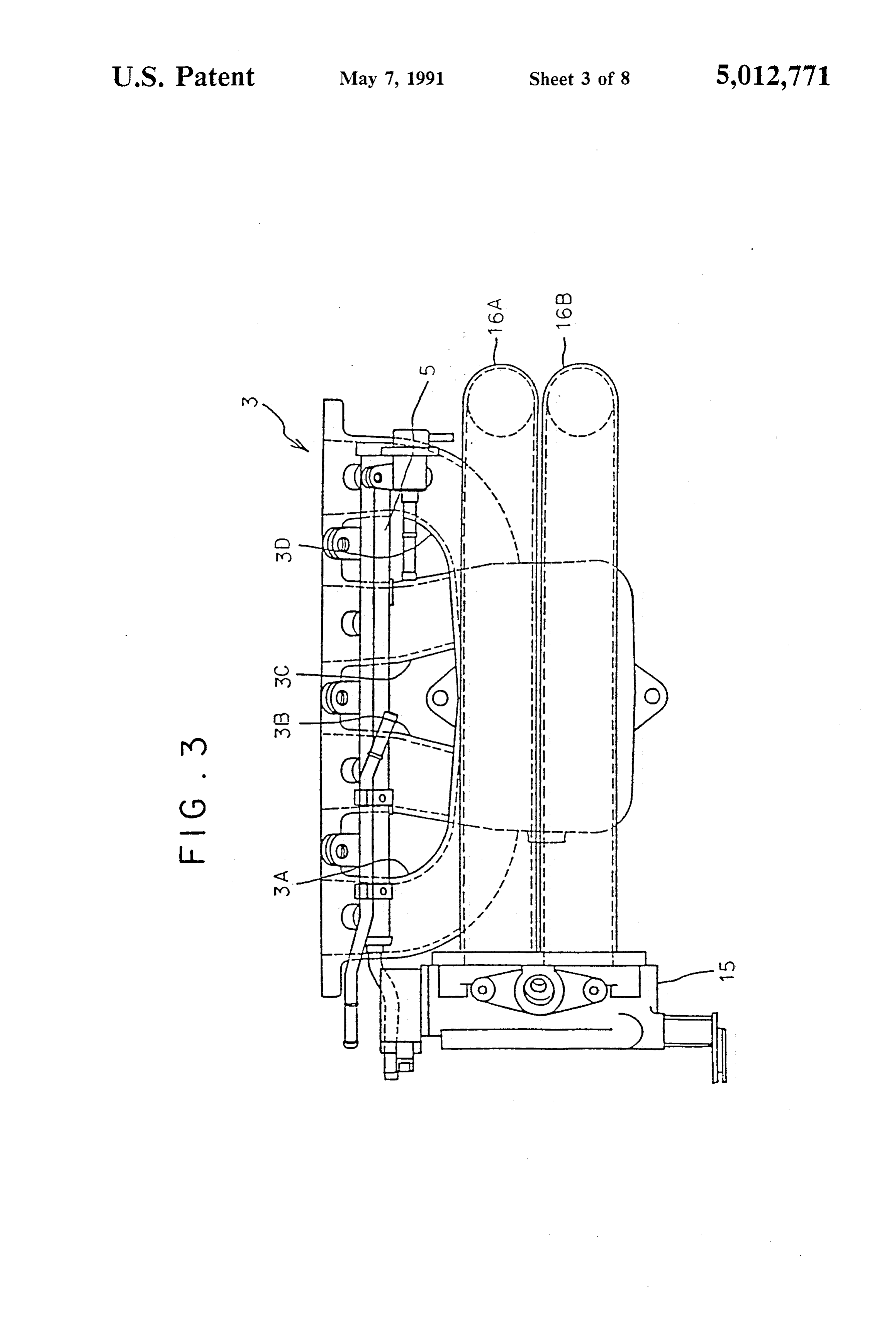
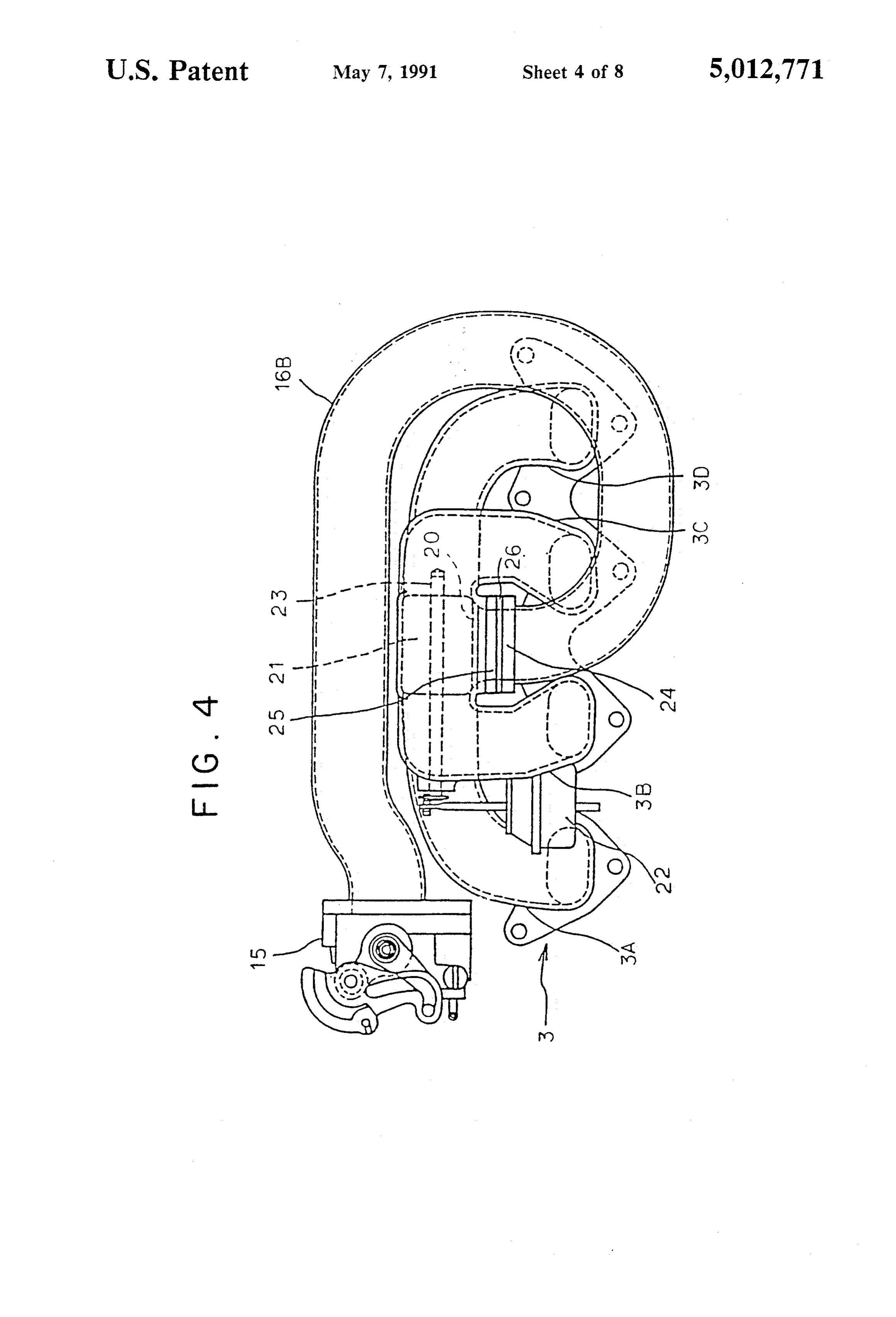
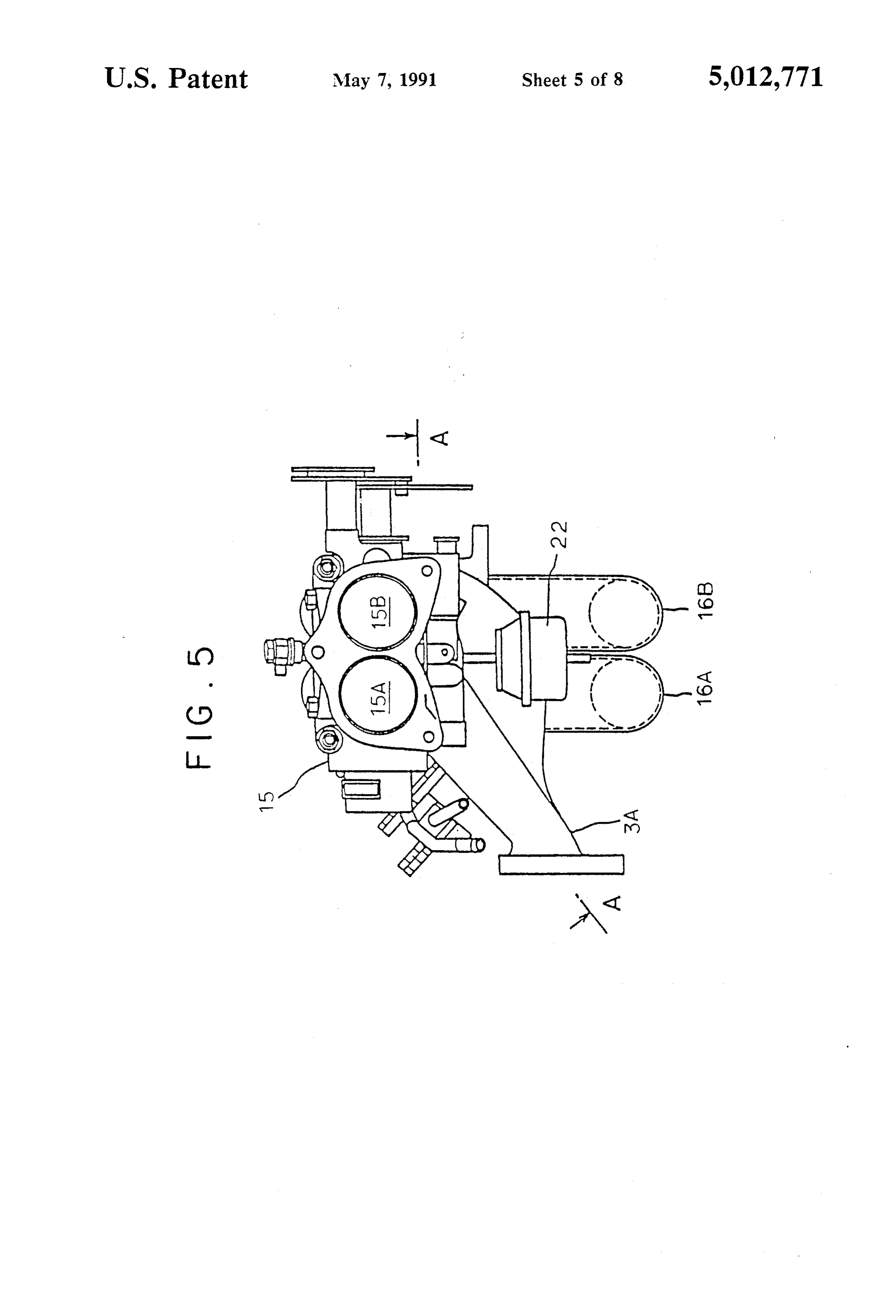
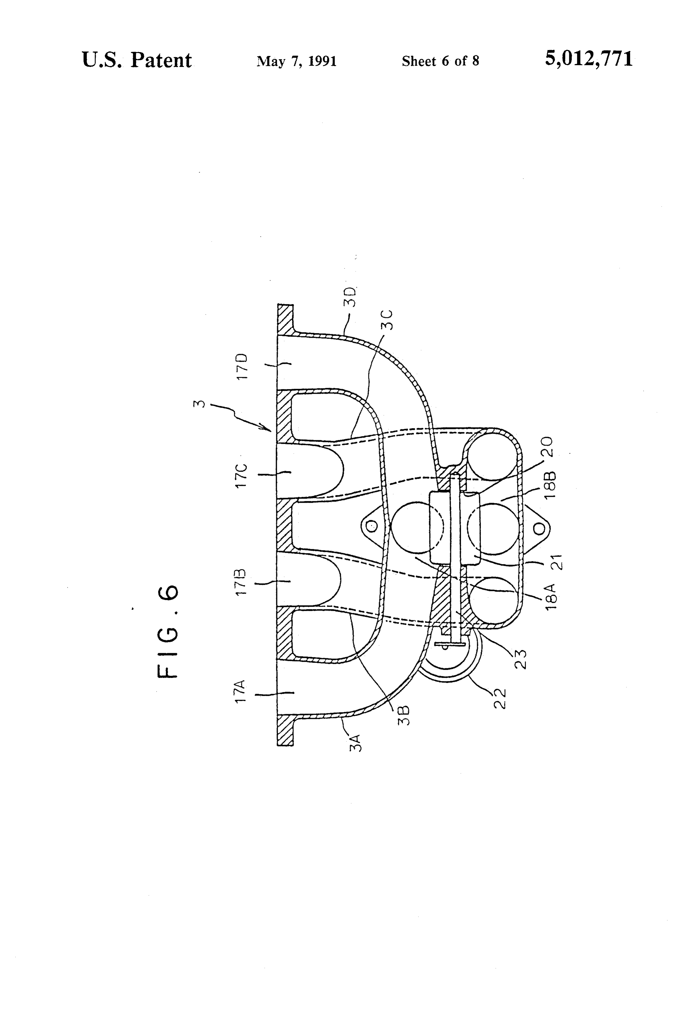
It is known to provide an intake system with a super ordinary skill in the art from the following description charger developed with improved charging efficiency of the preferred embodiments considered together with by utilizing kinetic effects, such as inertia effects or the accompanying drawings, wherein like reference resonance effects, of intake air by providing two intake 20 numbers have been used in different figures to denote pipes, respectively, communicating with two groups of the same parts in structure and operation and in which: discrete intake passages connected to two groups of FIG. 1 is a plan view showing a four-cylinder, in-line cylinders of an engine which in each and the same engine having an intake system in accordance with a group are not intended to be fired one after another, preferred embodiment of the present invention; respectively. One known type of such an intake system 25 FIG. 2 is a front view of FIG. 1; is adapted to increase intake charging efficiency by FIG. 3 is an enlarged plan view of the intake system setting a synchronizing engine speed desirable for pro shown in FIG. 1 viding inertia effects at a low speed. Such an intake FIG. 4 is a right side elevational view of FIG. 3; system is disclosed in Japanese Patent Publication No. FIG. 5 is a front view of FIG. 3; 60-14169 entitled "Intake System For Multi-Cylinder 30 FIG. 6 is a cross-sectional view take along line A-A Engine" issued April 11, 1985. in FIG. 5;
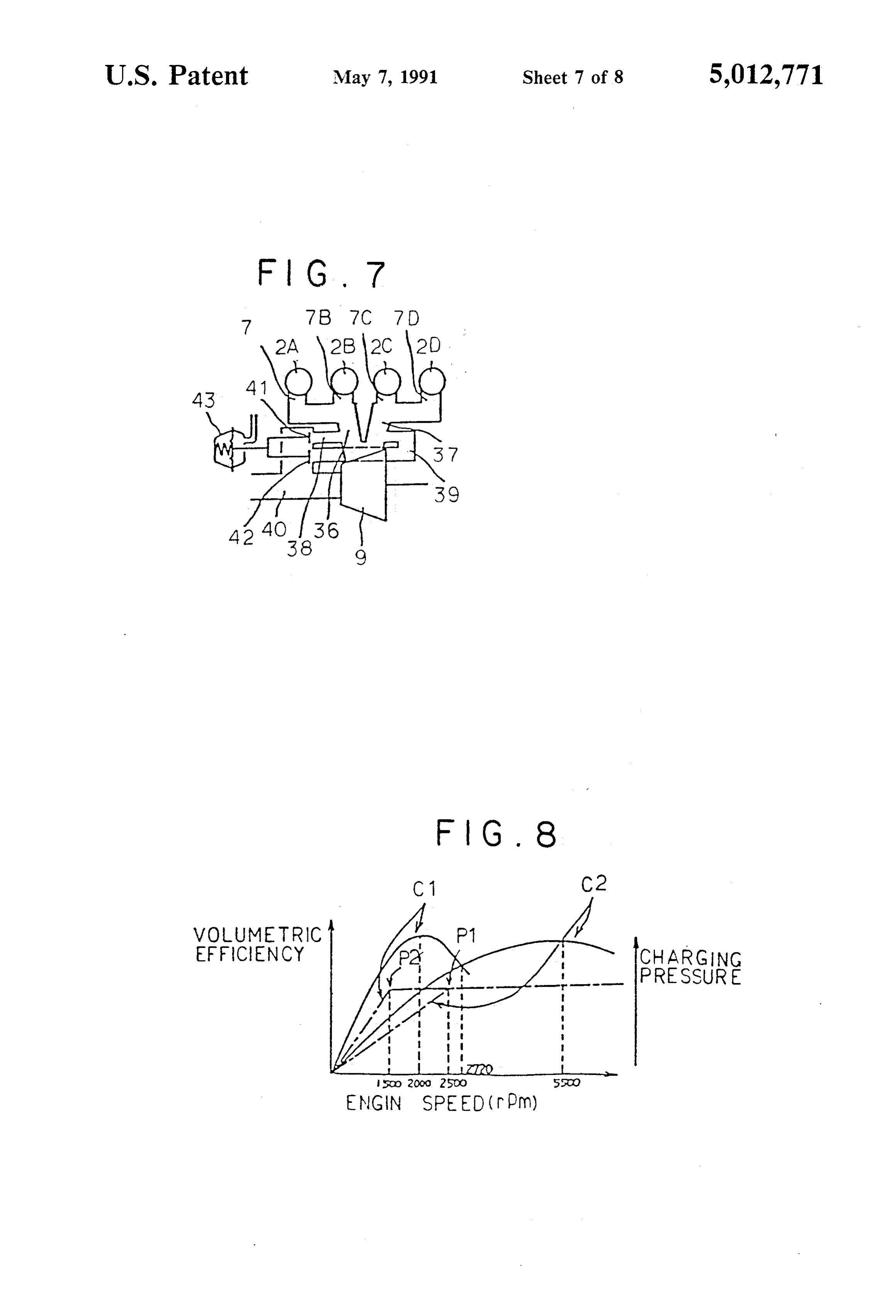
The provision of the intake system described in the FIG. 7 is a diagrammatical illustration showing an above publication, in which inertia effect is intensified exhaust system incorporated in the four-cylinder, in-line in a range of low engine speeds, allows engines with a engine of FIG. 1:
turbo-charger to compensate for a decrease of intake 35 FIG. 8 is a graph of characteristic curves of super charging efficiency caused by a decrease of driving enginecharging pressure and volumetric efficiency relative to force of a turbine of the turbo-charger in a range of low speed;
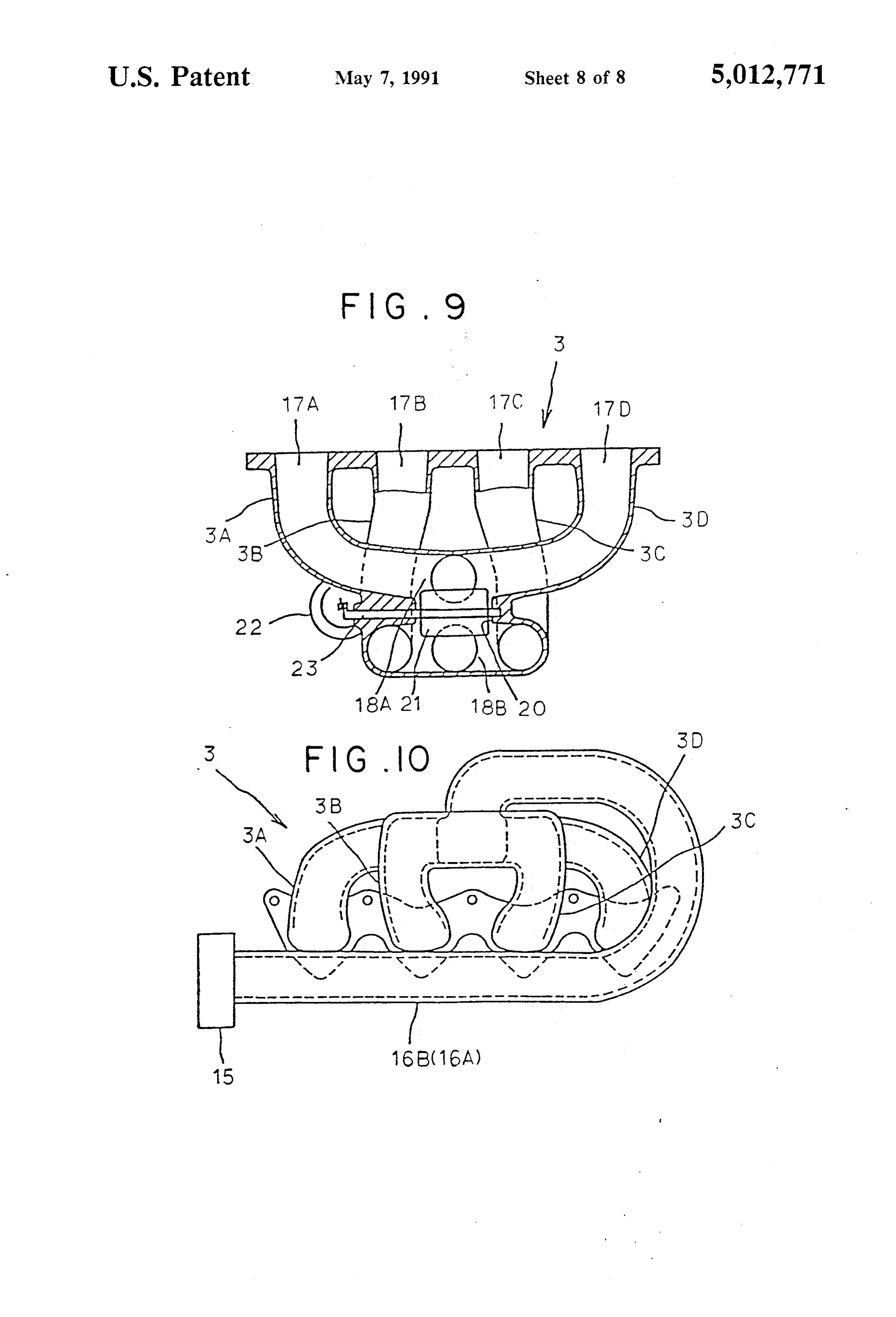
engine speeds. FIG. 9 is a side elevational view, similar to FIG. 6, The use of such an intake system has, however, a 40 preferredanembodiment showing intake system in accordance with another of the present invention; and drawback that a setting of the synchronizing speed FIG. 10 is a cross-sectional view, similar to FIG. 4, desirable for obtaining favorable inertia effects within a showing the intake system of FIG. 9. predetermined range of engine speed requires intake pipes whose overall length is considerably long, making DETALED DESCRIPTION OF THE it difficult to build a compact intake system. 45 PREFERRED EMBODIMENTS SUMMARY OF THE INVENTION An intake system in accordance with a preferred It is, therefore, a primary object of the present inven embodiment of the present invention includes a multi tion to provide an intake system for a multi-cylinder cylinder, in-line internal combustion engine. Because internal combustion engine which is entirely compact such multi-cylinder, in-line internal combustion engines and having a sufficient length intake pipe. are well known, this description will be directed in The above primary object is accomplished by provid particular to elements forming part of, or cooperating directly with, the intake system embodying the present ing an intake system for a multi-cylinder internal com invention. It is to be understood, however, that engine bustion engine having an engine body which includes a elements not specifically shown or described may take plurality of cylinders. The intake system comprises an 55 various forms known to those skilled in the art. It is intake manifold having a plurality of discrete intake noted that the term "front side" of the engine body 2 as passages connected to the plurality of cylinders, respec used herein should mean and refer to the upper side as tively, and two intake pipes, each intake pipe being viewed in FIG. 1.
arranged in such a way as to descend substantially verti Referring to the drawings, particularly to FIGS. 1 cally downwardly from a communicating portion 60 and 2, an engine body 2 of a four cylinder, in-line inter where the intake pipe communicates with each of two nal combustion engine, which is carried sideways in an groups of the intake passages, turns to extend horizon engine compartment 1 defined by a fender and a hood tally in one longitudinal direction of the engine body outlined in double-dotted lines 1A and 1B in FIGS. 1 and then turns back to extend in the opposite longitudi and 2, respectively, having an intake system in accor nal direction of the engine body surrounding the dis 65 dance with a preferred embodiment of the present in crete intake passages. vention is shown.
The two groups of discrete intake passages are con The engine body 2 is formed with No. 1 No. 2, No. nected to two groups of the cylinders which in each and 3 and No. 4 cylinders 2A to 2D in order from the front
Page 11
side of the engine body 2. The engine body 2 is attached lecting pipes 16A and 16B are connected at their down at its rear side with an intake manifold 3 which has first stream ends, which are formed with flanges 25, 24, to to fourth discrete intake pipes 3A to 3D connected to the intake manifold 3.
the cylinders No. 1 to No. 4 cylinders 2A to 2D, respec The intake manifold 3, as is clearly shown in FIG. 6, tively, and is usually cast from iron. The engine body 2 has a first connecting pipe portion 18A interconnecting is further attached at its front side with an exhaust mani passages 17A and 17D defined by the first and fourth fold 4 having first to fourth discrete exhaust pipes 4A to discrete intake pipes 3A and 3D and a second connect 4D connected to the first to the fourth cylinders 2A to ing pipe portion 18B interconnecting passages 17B and 2D, respectively. Connected to the intake manifold 3 is 17C defined by the second and third discrete intake a fuel distribution pipe 5 disposed above and along the O pipes 3B and 3C. The intake manifold 3 is placed so as first to fourth discrete intake pipes 3A to 3D and in a . to horizontally juxtapose these first and second con lengthwise direction of the engine body 2. This fuel necting pipe portions 18A and 18B to each other putting distribution pipe 5 is provided with first to fourth fuel the first connecting pipe portion 18A inside. These first injection nozzles (not shown) for delivering a correct and second connecting pipe portions 18A and 18B of amount of fuel into the first to fourth cylinders 2A to 15 the intake manifold 3 are, on one hand, connected to the 2D, respectively, for any given engine demand. On the first and second downstream side collecting pipes 16A other hand, disposed below the exhaust manifold 4 is a and 16B, respectively, through their flanges 25 and 24 turbocharger 6 for forcing air, under exhaust powered with gaskets 26 interposed therebetween and, on the pressure, into the first to fourth cylinders 2A to 2D. In other hand, communicated with each other by way of a the exhaust manifold 4, exhaust passages 7A to 7D re 20 passage 20 having a rectangular cross-section and ori spectively formed in the first to fourth discrete exhaust ented perpendicularly to the engine body 2 in its longi pipes 4A to 4D are divided into two groups for two tudinal direction, which passage 20 is provided therein cylinder groups, namely a first group of the first and with a butterfly valve 21. This butterfly valve 21 has a second cylinders 2A and 2B and a second group of the valve shaft 23 with its one end provided with an actua third and fourth cylinders 2C and 2D, by a partition 25 tor 22 of the type of diaphragm.
wall 8 and the passages in each group are communi By laying the first and second downstream side intake cated in one and the same connecting pipe 7AB, 7CD collecting pipes 16A and 16B to surround the intake independently connected to a turbine 9 of the turbo manifold 3 it is possible to take advantage of a space charger 6. generally left around the intake manifold 3 and allows Connected to the turbocharger 6 through the turbine 30 to provide the first and second downstream side intake 9 thereof is a blower i0 having an inlet port 10A which collecting pipes 16A and 16B in a compact space and opens toward the front side of the engine body 2 and is with long passages. Additionally, because of the first connected to an intake pipe 11 with an airflow meter and second downstream side intake collecting pipes and an air cleaner (not shown) and an outlet port 10B 16A and 16B having a substantially equal length, distri opening at its bottom which is connected to an inlet port 35 bution of intake air between the first and second down 2A of an intercooler 12 by way of an intake pipe 13. stream side intake collecting pipes 16A and 16B can be The intercooler 12, disposed on one lateral side of the improved in various proportions. Furthermore, because engine body 2 near the front end of the engine room 2, of the first and second downstream side intake collect is connected at the inlet port 12A formed in an upper ing pipes 16A and 16B are aluminum pipes, the intake portion of its side wall to the blower 10 of the turbo 40 pipe system is apt to crush upon a car crash, thereby charger 6 by way of the intake pipe 13 and at its outlet absorbing shock so as to protect a fuel system disposed port 12B formed right below the inlet port 12A in the in cooperation therewith.
side wall to an upstream end of an upstream side intake Reference is now made to FIG. 7 diagrammatically collecting pipe 14. The intake collecting pipe 14 illustrating an exhaust system cooperating with the branches off into two, namely first and second, up 45 engine intake system of the preferred embodiment of stream side intake collecting pipe branches 14A and 14B the present invention as depicted in FIGS. 1 through 6. which are connected at their downstream end to one First and second exhaust collecting pipes 36 and 37, are ends of barrels 15A and 15B of double barrel type throt commonly connected to the first and second exhaust tle body 15, respectively. Connected to the opposite passages 7A and 7B and third and fourth exhaust pas ends of the barrels 15A and 15B of the double barrel 50 sages 7C and 7D, respectively, communicate with the type throttle body 15, respectively, are first and second turbine 9 of the turbocharger 6 independently from downstream side intake collecting pipes 16A and 6B, each other. Bypass pipes 38 and 39, connecting a down which are made of aluminum pipe, Surrounding the stream portion of an exhaust pipe 40 of the turbine 9 of intake manifold 3. the turbocharger 6 with respect to the engine body 1 to FIGS. 3 to 5 show the layout of the intake manifold 55 the first and second exhaust pipes 36 and 37, is laid out 3 and its associated elements in detail. As shown, the bypassing the turbine 9 of the turbocharger 6. Both of first and second downstream side intake collecting pipes the bypass pipes 38 and 39 are, respectively, provided 16A and 16B, which are disposed side by side and hori with waste-gate valves 41 and 42 which are driven by a zontally in parallel with each other, extend from the common actuator 43.
first cylinder 2A toward the fourth cylinder 2D along 60 In the four cylinder, in-line internal combustion en the lateral side of the engine body 2 in a longitudinal gine 2, the No. 1 cylinder 2A, the No. 3 cylinder 2G, the direction in which the first to fourth cylinders 2A to 2D No. 4 cylinder 2D and the No. 2 cylinder 2B are fired in are disposed in order from the front side of the engine order. That is, the first to fourth cylinder 2A to 2D are body 2, turning back around the fourth discrete intake divided into two groups and the cylinders in each pipe 3D toward the first discrete intake pipe 3A and group, which are connected to one and the same con further extending substantially vertically upwardly be necting pipe portion 18A, 18B of the intake manifold 3, tween the second and third discrete intake pipes 3B and do not fire one after another. The discrete interconnect 3C. The first and second downstream side intake col ing pipes 17A to 17D for the No. 1 to No. 4 cylinders
Page 12
2A to 2D, the first and second downstream side intake turn back and extend in the other opposite longitudinal collecting pipes 16A and 16B connected to the first and direction of the engine body 2.
second connecting pipe portion 18A and 18B, and the It is to be noted that the intake system according to first and second upstream side intake collecting pipe the present invention may be incorporated in a multi branches 14A and 14B of the upstream side intake col cylinder internal combustion engine with no turbo char lecting pipe 14 connected to the first and second down gerIt provided.
is also understood that whereas the invention has stream side intake collecting pipes 16A and 16B, respec tively, through the throttle body 15 are so designed as beenferred fully described in detail with reference to the pre embodiments, nevertheless, various other em to provide a synchronizing point for the most effective 10 bodiments and variants are possible which are within inertia in each pipe or lower pipe portion when the the spirit and scope of the present invention, and such valve 21 is closed by the butterfly valve 21 at a speed of, embodiments and variants are intended to be covered for instance, 2,500 rpm at an intercept point P1 when by the following claims.
the passage 20 is open, as is shown in FIG. 8. The syn What is claimed is:
chronizing point is defined as a speed of the engine at 5 1. An intake system for a multi-cylinder internal con which a frequency depending upon engine rotation and bustion engine, said intake system comprising: the natural frequency of the intake system are well an engine having an engine body which includes a synchronized. An intercept point P2 shifts toward the plurality of cylinders;
side of lower engine speeds when the passage 20 is an intake manifold having a plurality of discrete in closed. On the other hand, when the valve 21 is open to 20 take passages connected to said plurality of cylin intercommunicate the first and second connecting pipe ders, respectively; and portions 18A and 18B, a synchronizing point for inertia two intake pipes, respectively communicating with effects shifts toward the side of higher engine speeds so two groups of said discrete intake passages con as to form a synchronized intake system suitable for nected to two groups of said cylinders which in high engine speeds. The valve 21, when the passage 20 25 each and the same group are not intended to be is open, is closed at engine speeds lower than a predeter fired one after another, each said intake pipe being mined speed higher than the intercept point for a high arranged to extend Substantially vertically from a engine speed synchronized intake system or opened at communicating portion where each said intake engine speed higher than the predetermined speed. Ac pipe communicates with a respective one of said cordingly, when the passage 20 is closed under low 30 groups of said intake passages, turns to extend hori engine speeds, intake charging efficiency or volumetric zontally in one longitudinal direction of said engine efficiency increases along the characteristic curve C1 body and turns back to extend in the opposite lon for a closed passage, more sharply, relative to the char gitudinal direction of said engine body surrounding acteristic curve C2 for an open passage as shown in 35 said discrete intake passages. FIG.8. Furthermore, the rising of supercharging pres 2. An intake system as defined in claim 1, wherein sure is sharp, so as to improve the responsiveness of said two communicating portions are disposed laterally acceleration. In a range of high engine speeds, intake to said engine body and arranged horizontally side by charging efficiency is increased by opening the passage side, thereby locating said two intake pipes in parallel with each other.
3. An intake system as defined in claim 2, wherein
FIGS. 9 and 10 shows an intake system in accordance said communication of said two intake pipes is disposed with another preferred embodiment of the present in midway of said discrete intake passages. vention in which the downstream side intake collecting 4. An intake system as defined in claim 1, wherein pipes 16A and 16B are differently laid out from the each said intake pipe rises substantially vertically up previous embodiment. As shown, the first and second 45 wardly from said communicating portion. downstream side intake collecting pipes 16A and 16B, 5. An intake system as defined in claim 1, wherein both of which are connected at their downstream end to each said intake pipe descends substantially vertically one end of barrels 15A and 15B of the two barrel type from said communicating portion.
throttle body 15, respectively, extend under the intake 6. An intake system as defined in claim 1, wherein manifold 3 in one longitudinal direction of the engine 50 said engine has four skcylinders arranged in-line. body 2, turn up at approximately a right angle and then k ck s se
Provenance
- Collection
- Cited prior art
- Original PDF
- patentimages.storage.googleapis.com →
- Filed
- 1990-02-28
- Pages
- 12
- Method
- pdftotext (the PDF's own text layer) + pdftoppm 300dpi page scans
- Source
- Google Patents bibliographic record
- Granted
- 1991-05-07
- Inventors
- Hiroyuki Oda; Toshimitsu Tanaka; Naoyuki Yamagata; Kazuhiko Hashimoto; Mazda Motor Corp
- Transcribed from
- patentimages.storage.googleapis.com →