patent · US5639232
Gas burner
17 June 1997
Page 1 — bibliographic record
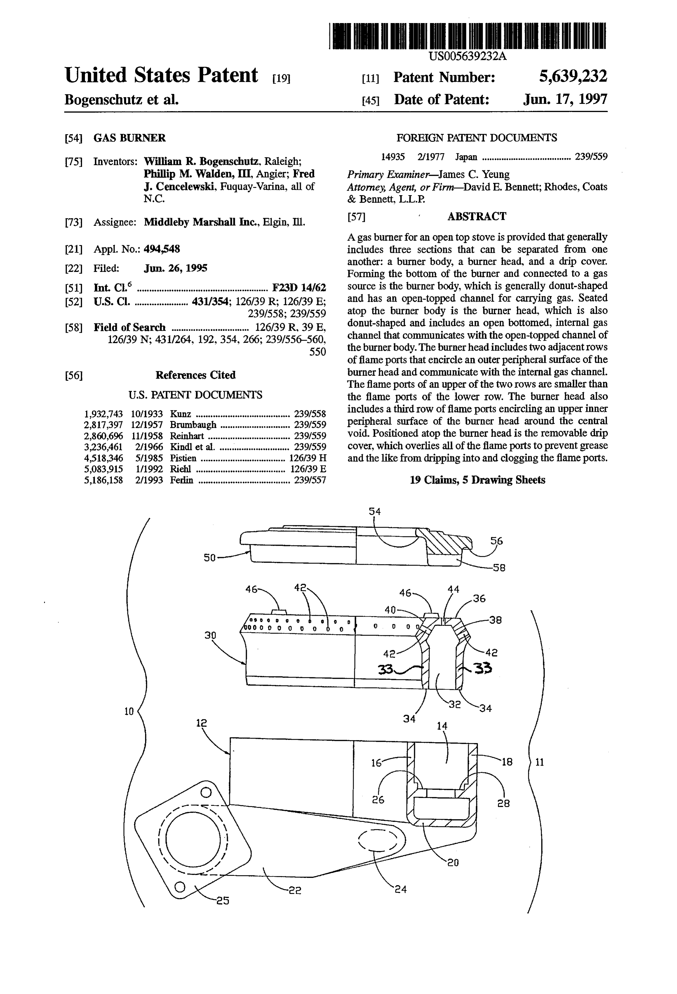
United States Patent 19 11 Patent Number: 5,639,232 Bogenschutz et al. 45 Date of Patent: Jun. 17, 1997 54 GAS BURNER FOREIGN PATENT DOCUMENTS 75 Inventors: William R. Bogenschutz, Raleigh; 14935 2/1977 Japan ..................................... 239/559 Philip M. Walden, III, Angier; Fred Primary Examiner-James C. Yeung
J. Cencelewski, Fuquay-Varina, all of Attorney, Agent, or Firm-David E. Bennett; Rhodes, Coats N.C. & Bennett, L.L.P.
73 Assignee: Middleby Marshall Inc., Elgin, Ill. 57 ABSTRACT A gas burner for an open top stove is provided that generally 21 Appl. No.: 494,548 includes three sections that can be separated from one 22 Fed: Jun. 26, 1995 another: a burner body, a burner head, and a drip cover. Forming the bottom of the burner and connected to a gas (51) Int. Cla. F23D 14/62 source is the burner body, which is generally donut-shaped 52 U.S. Cl. ...................... 431/354; 126/39 R; 126/39 E; and has an open-topped channel for carrying gas. Seated 239/558; 239/559 atop the burner body is the burner head, which is also 58 Field of Search ................................ 126/39 R, 39 E, donut-shaped and includes an open bottomed, internal gas 126/39 N: 431/264, 192,354, 266; 239/556-560, channel that communicates with the open-topped channel of 550 the burner body. The burner head includes two adjacentrows of flame ports that encircle an outer peripheral surface of the 56 References Cited burner head and communicate with the internal gas channel. The flame ports of an upper of the two rows are smaller than
1932,743 10/1933 Kunz ....................................... 239/558 includes a thirdrow of flame ports encircling an upper inner 2,817,397 12/1957 Brumbaugh ............................. 239/559 peripheral surface of the burner head around the central 2,860,696 11/1958 Reinhart ... . 239/559 void. Positioned atop the burner head is the removable drip 3,236,461 2/1966 Kindlet al. 239/559 cover, which overlies all of the flame ports to prevent grease 4,518,346 5/1985 Pistien ........... ... 126/39 H. and the like from dripping into and clogging the flame ports. 5,083,915 1/1992 Riehl ......... ... 126/39 E 5,186,158 2/1993 Ferlin ...................................... 239/557 19 Claims, 5 Drawing Sheets
Page 2
Drawing sheet — no readable text.
Page 3
Drawing sheet — no readable text.
Page 4
Drawing sheet — no readable text.
Page 5
Drawing sheet — no readable text.
Page 6
Drawing sheet — no readable text.
Page 7
GAS BURNER around the burner, while allowing flames from the Smaller, upper flame ports to combust mainly gas and air delivered
FIELD OF THE INVENTION from the internal gas channel within the burner. Therefore, the burner of the invention burns with much hotter, harder
The present invention generally pertains to gas appliances 5 flames than conventional burners. Athird row of flame ports and more particularly to the design of a gas burner for a gas is formed in the inner bevel surface to supplement the two appliance. outer rows of flame ports.
BACKGROUND OF THE INVENTION In another aspect of the present invention, the burner of the present invention includes aremovable drip cover which
Conventional gas burners for open-top gas appliances are O overlies the flame ports to prevent grease and the like from designed to operate efficiently up to approximately 20,000 to clogging them. To center the drip cover over the burner head 30,000 BTUs. Attempts at creating higher output burners and prevent the drip cover from sliding out of place, the that efficiently provide up to 40,000 BTUs of heat have not burner head includes nubs on its top surface that engage been successful. Burners which are designed to operate corresponding indentations in the bottom surface of the drip efficiently with an output of 20,000 to 30,000 BTUs will not 5 COWe operate as efficiently at higher outputs. This drop in effi Accordingly, in view of the above, an object of the present ciency has two undesirable results. First, lower efficiency invention is to provide a stove-top gas burner that efficiently results in an unnecessary waste of fuel which is not com produces up to 40,000 BTU's of heat. pletely combusted. Second, the lower efficiency means that Another object of the present invention is to provide a more undesirable bi-products, such as carbon monoxide, are 20 stove-top gas burner that includes a removable drip cover produced during combustion.
In order to obtain acceptable efficiency levels at higher that allows easier cleaning of the burner and that can be outputs, it has been necessary in the past to design the higher removed when not needed.
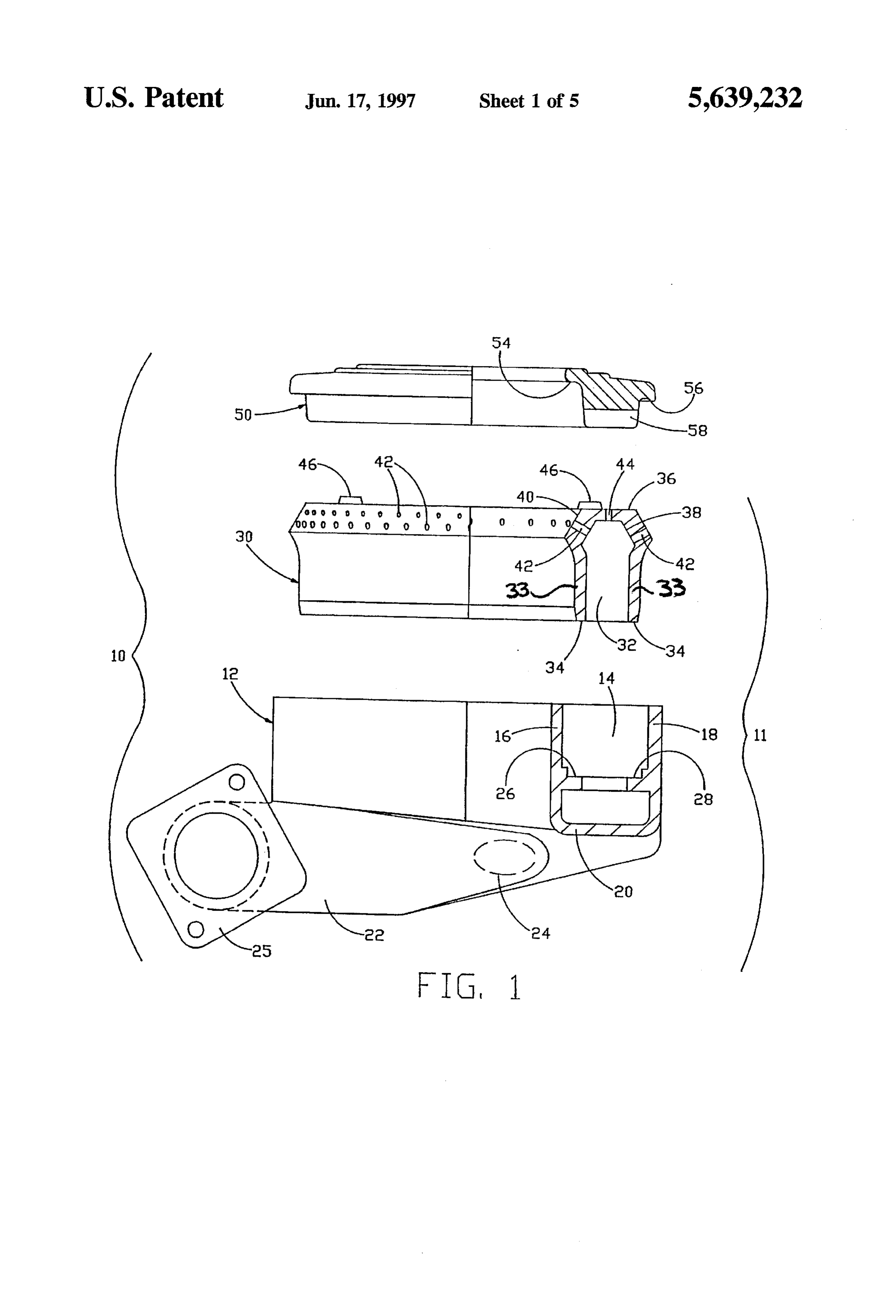
output burners from the ground up. Higher output burners Other objects and advantages of the present invention will tend to be larger than lower output burners and few com 25 become apparent and obvious from a study of the following description and the accompanying drawings, which are ponents are interchangeable. The need to manufacture and maintain a separate inventory of components for high output merely illustrative of such invention. burners results in increased costs. Furthermore, because BRIEF DESCRIPTION OF THE DRAWINGS higher output burners are often larger than lower output burners, they do not always fit into stoves designed for lower 30 FIG. 1 is an exploded elevation view of the gas burner of output burners. the present invention with a quarter-section of the burner Another limitation of conventional gas burners is the lack removed.
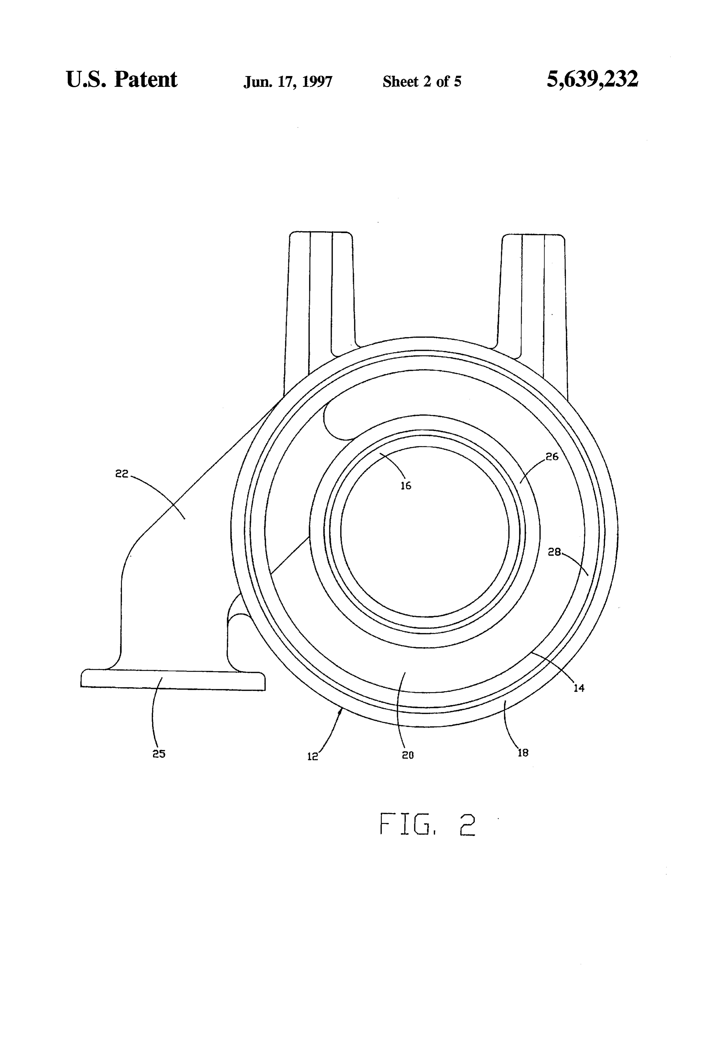
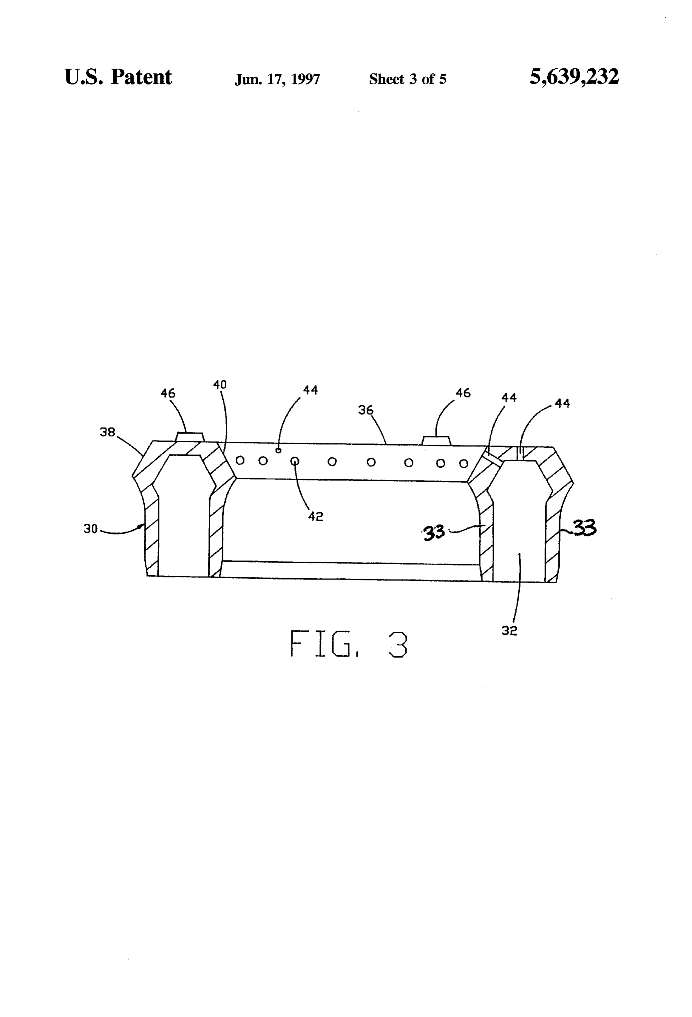
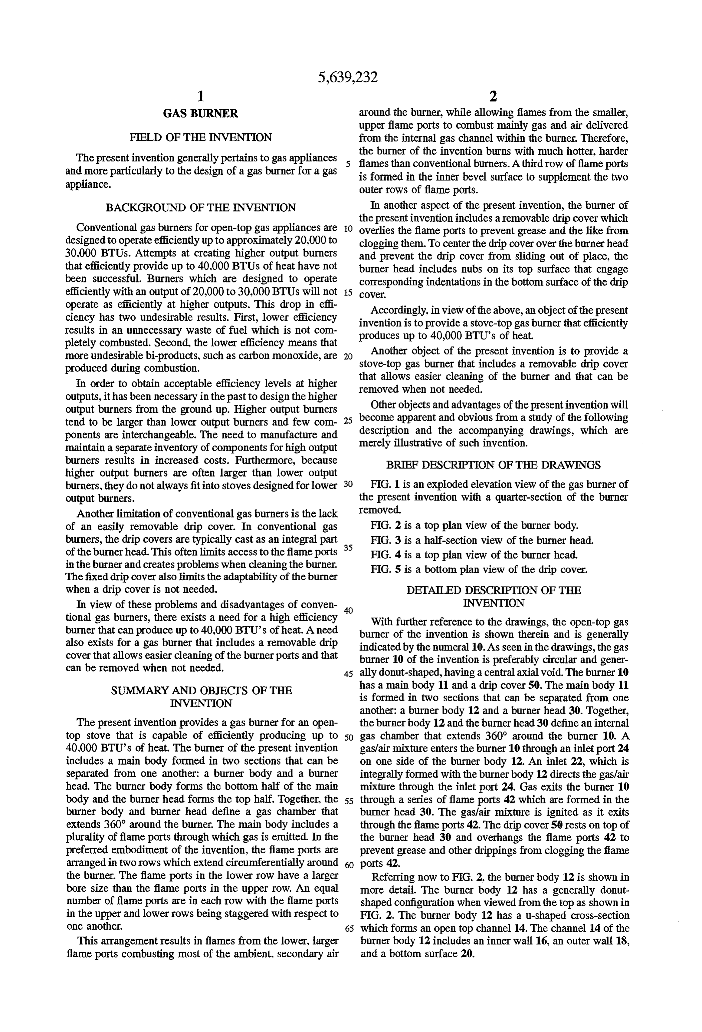
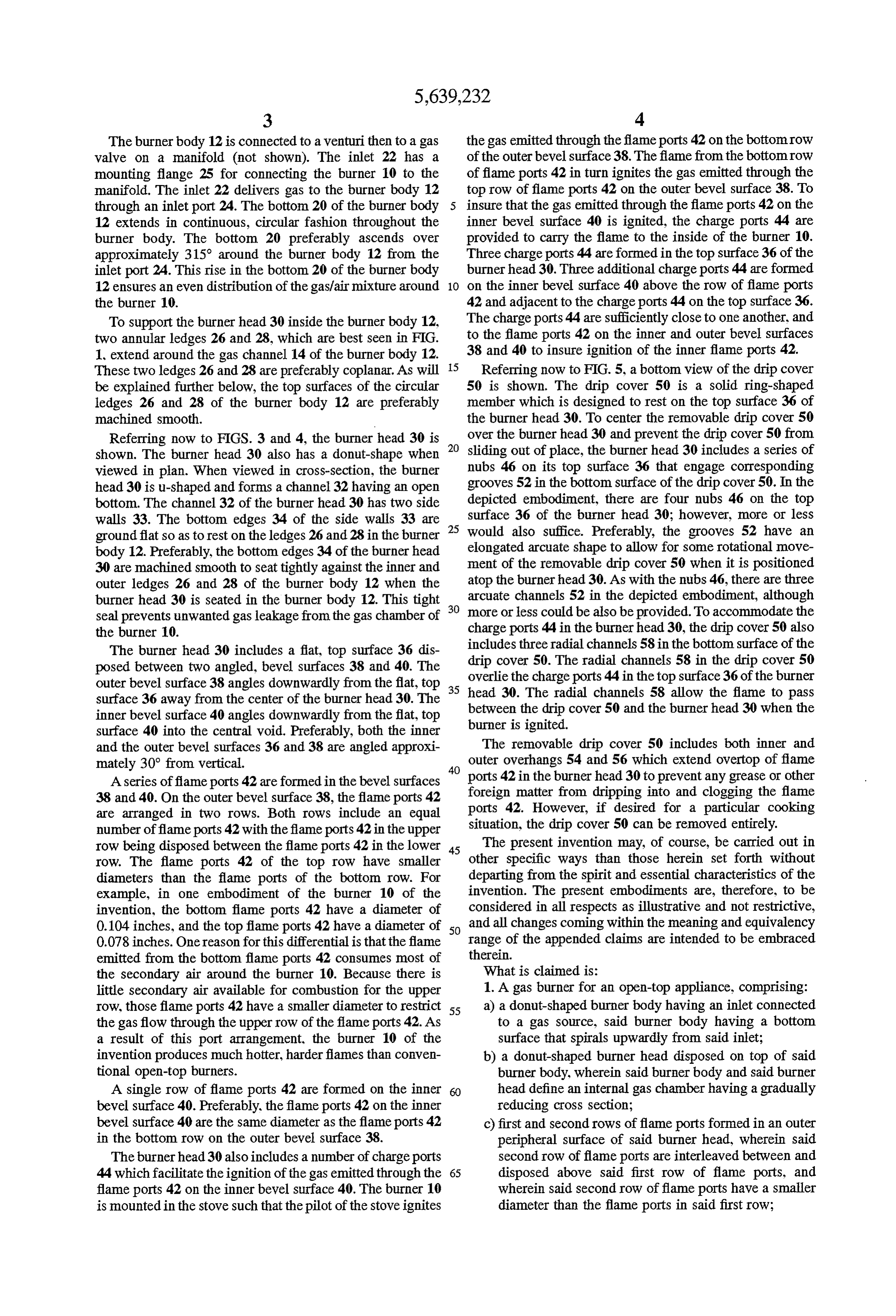
of an easily removable drip cover. In conventional gas FIG. 2 is a top plan view of the burner body. burners, the drip covers are typically cast as an integral part 35 FIG. 3 is a half-section view of the burner head. of the burnerhead. This often limits access to the flame ports FIG. 4 is a top plan view of the burner head. in the burner and creates problems when cleaning the burner. FIG. 5 is a bottom plan view of the drip cover. The fixed drip cover also limits the adaptability of the burner when a drip cover is not needed. DETALED DESCRIPTION OF THE In view of these problems and disadvantages of conven INVENTION tional gas burners, there exists a need for a high efficiency With further reference to the drawings, the open-top gas burner that can produce up to 40,000 BTU's of heat. A need burner of the invention is shown therein and is generally also exists for a gas burner that includes a removable drip indicated by the numeral 10. As seen in the drawings, the gas cover that allows easier cleaning of the burner ports and that burner 10 of the invention is preferably circular and gener can be removed when not needed. 45 ally donut-shaped, having a central axial void. The burner 10 SUMMARY AND OBJECTS OF THE has a main body 11 and a drip cover 50. The main body 11 INVENTION is formed in two sections that can be separated from one another: a burner body 12 and a burner head 30. Together,
The present invention provides a gas burner for an open the burner body 12 and the burner head 30 define an internal top stove that is capable of efficiently producing up to 50 gas chamber that extends 360° around the burner 10. A 40,000 BTU's of heat. The burner of the present invention gas/air mixture enters the burner 10 through an inlet port 24 includes a main body formed in two sections that can be on one side of the burner body 12. An inlet 22, which is separated from one another: a burner body and a burner integrally formed with the burner body 12 directs the gas/air head. The burner body forms the bottom half of the main mixture through the inlet port 24. Gas exits the burner 10 body and the burner head forms the top half. Together, the 55 through a series of flame ports 42 which are formed in the burner body and burner head define a gas chamber that burner head 30. The gasfair mixture is ignited as it exits extends 360° around the burner. The main body includes a through the flame ports 42. The drip cover 50 rests on top of plurality of flame ports through which gas is emitted. In the the burner head 30 and overhangs the flame ports 42 to preferred embodiment of the invention, the flame ports are prevent grease and other drippings from clogging the flame arranged in two rows which extend circumferentially around ports 42.
the burner. The flame ports in the lower row have a larger Referring now to FIG. 2, the burner body 12 is shown in bore size than the flame ports in the upper row. An equal more detail. The burner body 12 has a generally donut number of flame ports are in each row with the flame ports shaped configuration when viewed from the top as shown in in the upper and lower rows being staggered with respect to FIG. 2. The burner body 12 has a u-shaped cross-section one another. 65 which forms an open top channel 14. The channel 14 of the This arrangement results in flames from the lower, larger burner body 12 includes an inner wall 16, an outer wall 18, flame ports combusting most of the ambient, secondary air and a bottom surface 20.
Page 8
The burner body 12 is connected to a venturi then to a gas the gas emitted through the flame ports 42 on the bottom row valve on a manifold (not shown). The inlet 22 has a of the outer bevel surface 38. The flame from the bottom row mounting flange 25 for connecting the burner 10 to the of flame ports 42 in turn ignites the gas emitted through the manifold. The inlet 22 delivers gas to the burner body 12 top row of flame ports 42 on the outer bevel surface 38. To through an inlet port 24. The bottom 20 of the burner body insure that the gas emitted through the flame ports 42 on the 12 extends in continuous, circular fashion throughout the inner bevel surface 40 is ignited, the charge ports 44 are burner body. The bottom 20 preferably ascends over provided to carry the flame to the inside of the burner 10. approximately 315° around the burner body 12 from the Three charge ports 44 are formed in the top surface 36 of the inlet port 24. This rise in the bottom 20 of the burner body burner head 30. Three additional charge ports 44 are formed 12 ensures an even distribution of the gas/air mixture around 10 on the inner bevel surface 40 above the row of flame ports the burner 10. 42 and adjacent to the charge ports 44 on the top surface 36. To support the burner head 30 inside the burner body 12, The charge ports 44 are sufficiently close to one another, and two annular ledges 26 and 28, which are best seen in FIG. to the flame ports 42 on the inner and outer bevel surfaces 1, extend around the gas channel 14 of the burner body 12. 38 and 40 to insure ignition of the inner flame ports 42. These two ledges 26 and 28 are preferably coplanar. As will 15 Referring now to FIG. 5, a bottom view of the drip cover be explained further below, the top surfaces of the circular 50 is shown. The drip cover 50 is a solid ring-shaped ledges 26 and 28 of the burner body 12 are preferably member which is designed to rest on the top surface 36 of machined Smooth. the burner head 30. To center the removable drip cover 50 Referring now to FIGS. 3 and 4, the burner head 30 is over the burner head 30 and prevent the drip cover 50 from shown. The burner head 30 also has a donut-shape when sliding out of place, the burner head 30 includes a series of viewed in plan. When viewed in cross-section, the burner nubs 46 on its top surface 36 that engage corresponding head 30 is u-shaped and forms a channel 32 having an open grooves 52 in the bottom surface of the drip cover 50. In the bottom. The channel 32 of the burner head 30 has two side depicted embodiment, there are four nubs 46 on the top walls 33. The bottom edges 34 of the side walls 33 are 25 surface 36 of the burner head 30; however, more or less ground flat so as to rest on the ledges 26 and 28 in the burner would also suffice. Preferably, the grooves 52 have an body 12. Preferably, the bottom edges 34 of the burner head elongated arcuate shape to allow for some rotational move 30 are machined smooth to seat tightly against the inner and ment of the removable drip cover 50 when it is positioned outer ledges 26 and 28 of the burner body 12 when the atop the burner head 30. As with the nubs 46, there are three burner head 30 is seated in the burner body 12. This tight 30 arcuate channels 52 in the depicted embodiment, although Seal prevents unwanted gas leakage from the gas chamber of more or less could be also be provided. To accommodate the the burner 10. charge ports 44 in the burner head 30, the drip cover 50 also includes three radial channels 58 in the bottom surface of the
The burner head 30 includes a flat, top surface 36 dis drip cover 50. The radial channels 58 in the drip cover 50 posed between two angled, bevel surfaces 38 and 40. The overlie the charge ports 44 in the top surface 36 of the burner outer bevel surface 38 angles downwardly from the flat, top 35 head 30. The radial channels 58 allow the flame to pass surface 36 away from the center of the burner head 30. The between inner bevel surface 40 angles downwardly from the flat, top burner isthe drip cover 50 and the burner head 30 when the ignited.
surface 40 into the central void. Preferably, both the inner and the outer bevel surfaces 36 and 38 are angled approxi The removable drip cover 50 includes both inner and mately 30° from vertical. 40 outer overhangs 54 and 56 which extend overtop of flame
A series offlame ports 42 are formed in the bevel surfaces ports 42 in the burner head 30 to prevent any grease or other 38 and 40. On the outer bevel surface 38, the flame ports 42 foreign matter from dripping into and clogging the flame are arranged in two rows. Both rows include an equal ports 42. However, if desired for a particular cooking number offlame ports 42 with the flame ports 42 in the upper situation, the drip cover 50 can be removed entirely. row being disposed between the flame ports 42 in the lower 45 The present invention may, of course, be carried out in row. The flame ports 42 of the top row have smaller other specific ways than those herein set forth without diameters than the flame ports of the bottom row. For departing from the spirit and essential characteristics of the example, in one embodiment of the burner 10 of the invention. The present embodiments are, therefore, to be invention, the bottom flame ports 42 have a diameter of considered in all respects as illustrative and not restrictive, 0.104 inches, and the top flame ports 42 have a diameter of 50 and all changes coming within the meaning and equivalency 0.078 inches. One reason for this differential is that the flame range of the appended claims are intended to be embraced emitted from the bottom flame ports 42 consumes most of therein.
the secondary air around the burner 10. Because there is What is claimed is:
little secondary air available for combustion for the upper 1. A gas burner for an open-top appliance, comprising: row, those flame ports 42 have a smaller diameter to restrict 55 a) a donut-shaped burner body having an inlet connected the gasflow through the upper row of the flame ports 42. As to a gas source, said burner body having a bottom a result of this port arrangement, the burner 10 of the surface that spirals upwardly from said inlet; invention produces much hotter, harder flames than conven b) a donut-shaped burner head disposed on top of said tional open-top burners. burner body, wherein said burner body and said burner A single row of flame ports 42 are formed on the inner head define an internal gas chamber having a gradually bevel surface 40. Preferably, the flame ports 42 on the inner reducing cross section;
bevel surface 40 are the same diameter as the flame ports 42 c) first and second rows of flame ports formed in an outer in the bottom row on the outer bevel surface 38. peripheral surface of said burner head, wherein said The burnerhead 30 also includes a number of charge ports second row of flame ports are interleaved between and 44 which facilitate the ignition of the gas emitted through the 65 disposed above said first row of flame ports, and flame ports 42 on the inner bevel surface 40. The burner 10 wherein said second row of flame ports have a smaller is mounted in the stove such that the pilot of the stove ignites diameter than the flame ports in said first row;
Page 9
d) a third row of flame ports formed in an inner peripheral top surface of said burner head, and wherein said at least one Surface of said burner head; and radial channel includes a plurality of radial channels formed e) at least one charge portformed in said burner head and in the bottom surface of the removable drip cover. communicating with said internal gas chamber for 14. The gas burner of claim 8 wherein the burner head is carrying aflame from the rows of flame ports in the first donut-shaped, having a central void therethrough and gen peripheral surface to the row of flame ports in the erally flat, ring-shaped top surface disposed between inner second peripheral surface. and outer angled, beveled surfaces, wherein the burner head 2. The gas burner of claim 1 further comprising a remov includes an inner row of flame ports encircling the inner able drip cover seated atop the burner head and overlying the angled bevel surface of the burner head and surrounding the rows of flame ports and the at least one charge port. 10 central void, each flame port of the inner row communicat 3. The gas burner of claim 1 wherein said burner head ing with the gas chamber, and wherein the burner head includes a generally flat top surface disposed between inner includes at least one outer row of flame ports encircling the and outer angled, bevel surfaces. outer angled bevel surface of the burner head, each flame 4. The gas burner of claim3 wherein the first and second port of theatlestone outer row communicating with the gas rows of flame ports are disposed in said outer bevel surface 15 chamber.
and wherein the third row of flame ports is disposed in said charge 15. The gas burner of claim 14 wherein said at least one inner bevel surface. port includes a plurality of charge ports disposed in 5. The gas burner of claim 4 wherein the at least one the flattop surface between the inner and outer angled bevel charge port includes a plurality of charge ports disposed in Surfaces.16. The gas burner of claim 14, wherein said at least one said flat top surface. 20 charge port is disposed in the flat top surface between the 6. The gas burner of claim 1 wherein the removable drip inner and outer angle bevel surfaces, said at least one charge cover includes at least one radial channel formed in a bottom port for carrying the gas flame from the flame ports in the surface thereof, said at least one radial channel overlying outer angle bevel Surface to the flame ports in the inner angle said at least one charge port to allow the flame to pass from bevel surface.
the rows of flame ports in the first peripheral surface to the 25 17. A gas burner, comprising:
row of flame ports in the second peripheral surface. a) a burner head connected to a gas source and including 7. The gas burner of claim 1, wherein the flame ports in an internal gas chamber, the burner head including: said second row have a smaller diameter than the flame ports i) a first row of flame ports encircling an outer periph in said first row, the ratio of the diameter of the flame ports eral surface of the burner head, wherein each flame in said second row to the diameter of the flame ports in said 30 port of the first row communicates with the gas first row being approximately 0.078 to 0.104. chamber, 8. A gas burner for an open-top appliance comprising: ii) a second row of flame ports encircling the outer a) a donut-shaped burner body having an inlet connected peripheral surface of the burner head adjacent to and to a gas source, said burner body having a bottom above the first row of flame ports, wherein each surface that spirals upwardly from said inlet; 35 flame port of the second row communicates with the b) a donut-shaped burner head disposed on top of said gas chamber, burner body, wherein said burner body and said burner iii) a third row of flame ports encircling an inner head define an internal gas chamber having a gradually peripheral surface of the burner head, wherein each reducing cross section; flame port of the third row communicates with the c) first and second rows of flame ports formed in an outer gas chamber, and peripheral surface of said burner head, wherein said iv) a plurality of charge ports disposed in a top surface second row of flame ports are interleaved between and of the burner head between the inner and outer disposed above said first row of flame ports, and peripheral surfaces, wherein each charge port com wherein said second row of flame ports have a smaller municates with the gas chamber, said charge ports diameter than the flame ports in said first row; and 45 for carrying a flame from the flame ports encircling d) a thirdrow of flame ports formed in an inner peripheral the outer peripheral surface to the flame ports encir surface of said burner head. cling the inner peripheral surface; and 9. The gas burner of claim 8 further comprising a remov b) aremovable drip cover seated atop the burner head and able drip cover positioned on top of the burner head and overlying the first and second rows of flame ports and overlying the flame ports and the at least one charge port to 50 the charge ports, wherein the removable drip cover protect the flame ports and the at least one charge port from includes a plurality of radial channels in a bottom grease and other drippings. surface of the removable drip cover, said radial chan 10. The gas burner of claim 9 wherein the burner head nels overlying the charge ports in the top surface of the further includes a plurality of convex nubs on a top surface burner head to permit the flame to pass between the of the burner head, and wherein the removable drip cover 55 removable drip cover and the burner head when the includes in a bottom surface thereof a plurality of concave burner is ignited.
indentations for engaging the convex nubs when the drip 18. The gas burner of claim 17 wherein the burner head cover is positioned atop the burner head. is donut-shaped, having a central void therethrough and a 11. The gas burner of claim 10 wherein the concave ring-shaped top surface, and wherein the removable drip indentations in the bottom surface of the removable drip cover is also ring-shaped.
cover form elongated arcuate channels. 19. The gas burner of claim 17 wherein the flame ports in 12. The gas burner of claim.9 wherein the removable drip said second row have a Smaller diameter than the flame ports cover includes at least one radial channel formed in a bottom in said first row, the ratio of the diameter of the flame ports surface thereof, said at least one radial channel overlying in said second row to the diameter of the flame ports in said said at least one charge port. 65 first row being approximately 0.078 to 0.104. 13. The gas burner of claim 12 wherein said at least one charge port includes a plurality of charge ports formed in a :: * : : :
Provenance
- Collection
- Cited prior art
- Original PDF
- patentimages.storage.googleapis.com →
- Filed
- 1995-06-26
- Pages
- 9
- Method
- pdftotext (the PDF's own text layer) + pdftoppm 300dpi page scans
- Source
- Google Patents bibliographic record
- Granted
- 1997-06-17
- Inventors
- William R. Bogenschutz; Phillip M. Walden, III; Fred J. Cencelewski; Middleby Marshall Inc
- Transcribed from
- patentimages.storage.googleapis.com →