patent · US5186158
Gas burner
16 February 1993
Page 1 — bibliographic record
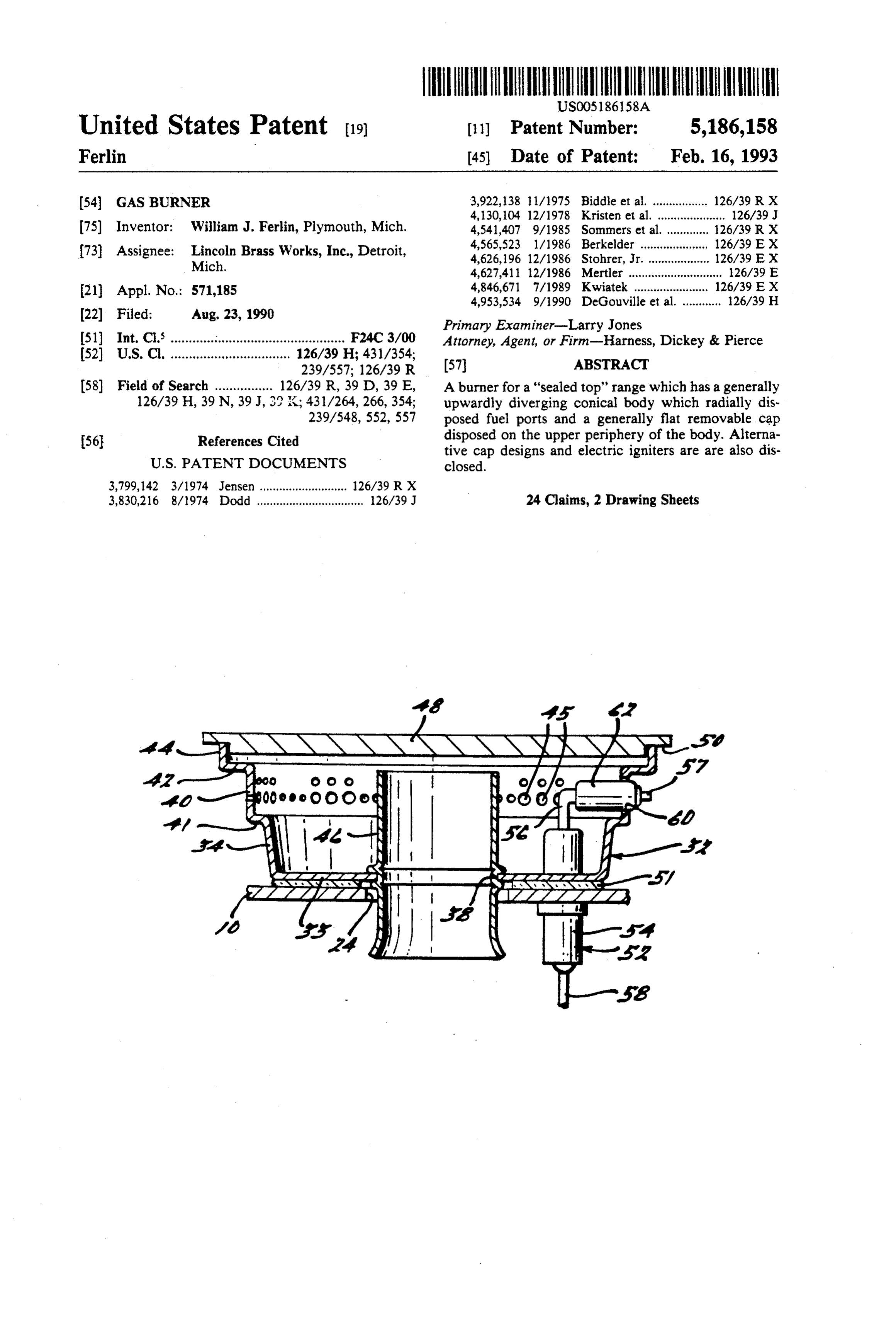
United States Patent 19 11) Patent Number: 5,186,158 Ferlin (45) Date of Patent: Feb. 16, 1993 54 GAS BURNER 3,922,138 li/1975 Biddle et al. ................. 126/39 RX 4,130,104 12/1978 Kristen et al. ..................... 26/39 J 75) Inventor: William J. Ferlin, Plymouth, Mich. 4,541,407 9/1985 Sommers et al. ............. 126/39 RX 73) Assignee: Lincoln Brass Works, Inc., Detroit, 4,565,523 1/1986 Berkelder ......... ... 126/39 E X Mich. 4,626,196 12/1986 Stohrer, Jr. ... ... 126/39 E X 4,627,4ll 12/1986 Mertler ............................. 126/39 E 21 Appl. No.: 571,185 4,846,671 7/1989 Kwiatek ....................... 126/39 E X
22 Filed: Aug. 23, 1990 Primary Examiner-Larry Jones 51) Int. Cl. ............................................... F24C 3/OO Attorney, Agent, or Firm-Harness, Dickey & Pierce 52 U.S. C. .... ... 126/39 H; 431/354; 57 ABSTRACT
58 Field of Search ................ 126/39 R, 39 D, 39 E, A burner for a "sealed top' range which has a generally 126/39 H, 39N, 39J, 39 K; 431/264, 266,354; upwardly diverging conical body which radially dis 239/548,552, 557 posed fuel ports and a generally flat removable cap 56 References Cited disposed on the upper periphery of the body. Alterna tive cap designs and electric igniters are are also dis
3,830,216 8/1974 Dodd ................................. 26/39 J 24 Claims, 2 Drawing Sheets
ZZZZZZZ
Page 2
Drawing sheet — no readable text.
Page 3
Drawing sheet — no readable text.
Page 4
and ambient air, vertically upwardly into opening 24
The burner of the present invention generally com
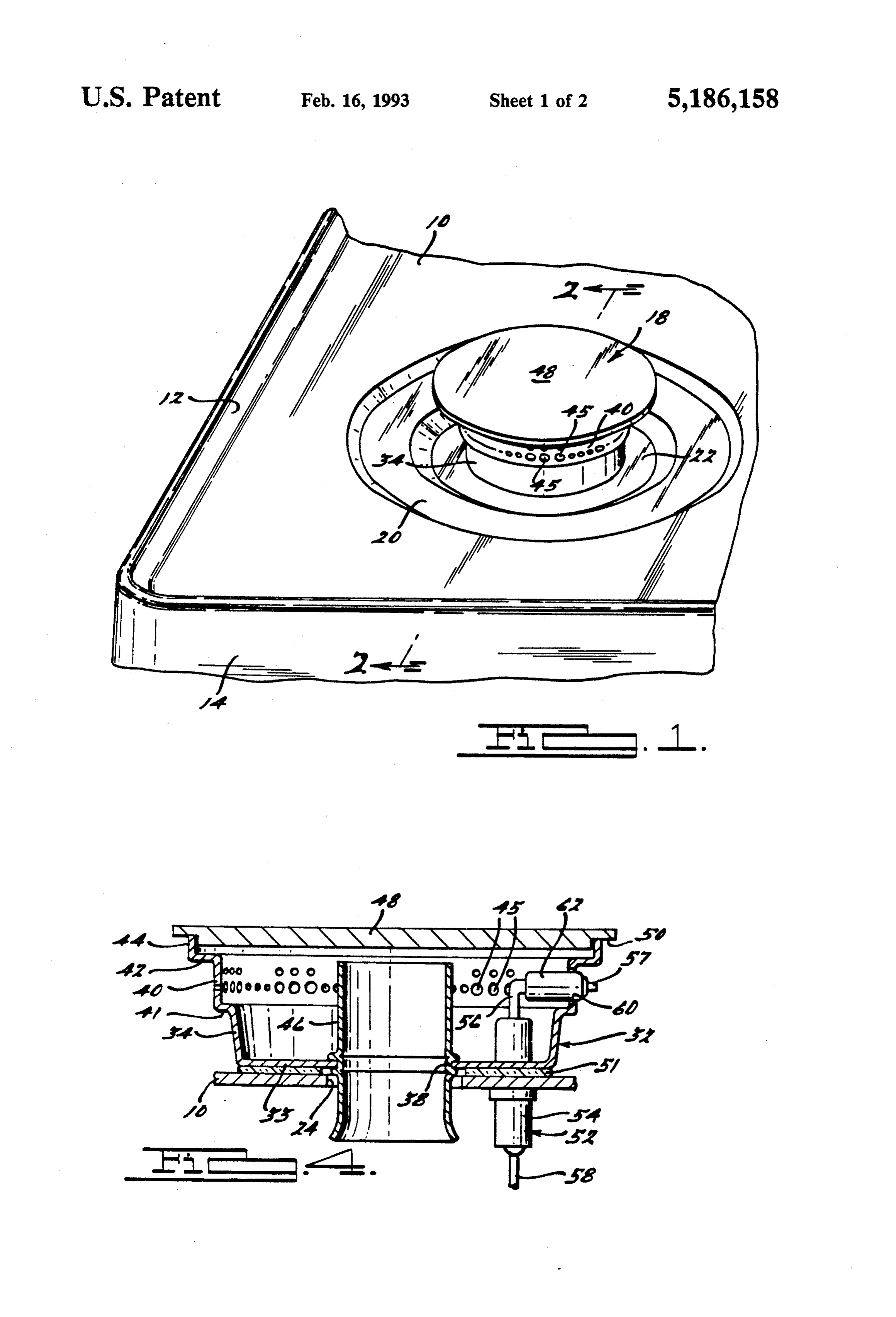
BACKGROUND AND SUMMARY OF THE prises a one-piece upwardly open generally cup-shaped INVENTION sheet-metal burner body 32 of generally circular cross The present invention relates to range top burners, 33 section and having a generally flat annular bottom wall and more particularly to an improved burner specifi fastened to top partition 10 by means of a plurality of cally adapted to be used in a range requiring "sealed fasteners 36, a gaseous fuel and air inlet port 38 (FIG. 4) disposed in alignment with opening 24, a generally top' burners. 10 cylindrical but slightly conical lower portion 34 joining One of the current trends in the design of gas fired the outer periphery of bottom wall 33 and extending kitchen ranges is the use of sealed top burners. This is an arrangement wherein there is no annular gap or air upwardly and slightly outwardly therefrom, a generally space around the burner: i.e., the top of the range en ery of lowerupper cylindrical portion 40 joining the upper periph portion 34 via a generally horizontal annu gages the entire periphery of the burner. This provides 15 lar flange 41 and having a cleaner look, and is actually cleaner because spillover lower portion 34, a firsta flange diameter greater than that of 42 extending radially material cannot now go down into the burner box outwardly from the upper periphery of upper portion below the former, but remains on top where it may be 40, a second flange 44 extending upwardly from the easily wiped up. Ranges of this type provide different problems and needs than those of a conventional range 20 outer periphery of first flange 42, a plurality of radially directed flame ports 45 extending through upper por top.
It is therefore a primary object of this invention to tube 40, tion a generally cylindrical venturi or gas mixing provide an extremely simple and inexpensive burner, disposed in bodyan32outwardly 46 having flared lower end centrally and affixed, by upsetting or crimp comprising only a few parts, which has good efficiency ing, to the edge of inlet port 38, and a generally horizon and is particularly suited for use on a sealed top range. 25 tal circular
A related object resides in the provision of such a ported by theflatupper imperforate burner cap 48 loosely sup periphery of second flange 44, said burner which is ideally suited for incorporation of elec cap being of an outside tronic ignition, with the igniter disposed either inside or that of second flange 44. diameter
slightly greater than as shown in FIGS. 1, outside of the burner itself. A further object resides in 2 and 4, is a relatively heavy casting, the provision of an alternative extra light-weight ver 30 iron, glass (clear or opaque) or the like,formed of cast which can be sion of a burner cap. easily lifted off for cleaning or service of the burner. An These and other objects and advantages will become annular notch 50 around the periphery thereof retains it more apparent when viewed in light of the accompany in position on body 32. Removal of the entire burner is ing drawings and following detailed description.
35 easily accomplished by removing the cap and then fas
BRIEF DESCRIPTION OF THE DRAWING teners 36. Preferably a layer 51 of heat insulating and FIGURES electrically non-conductive material is disposed be tween burners 18 and partition 16 to isolate the two
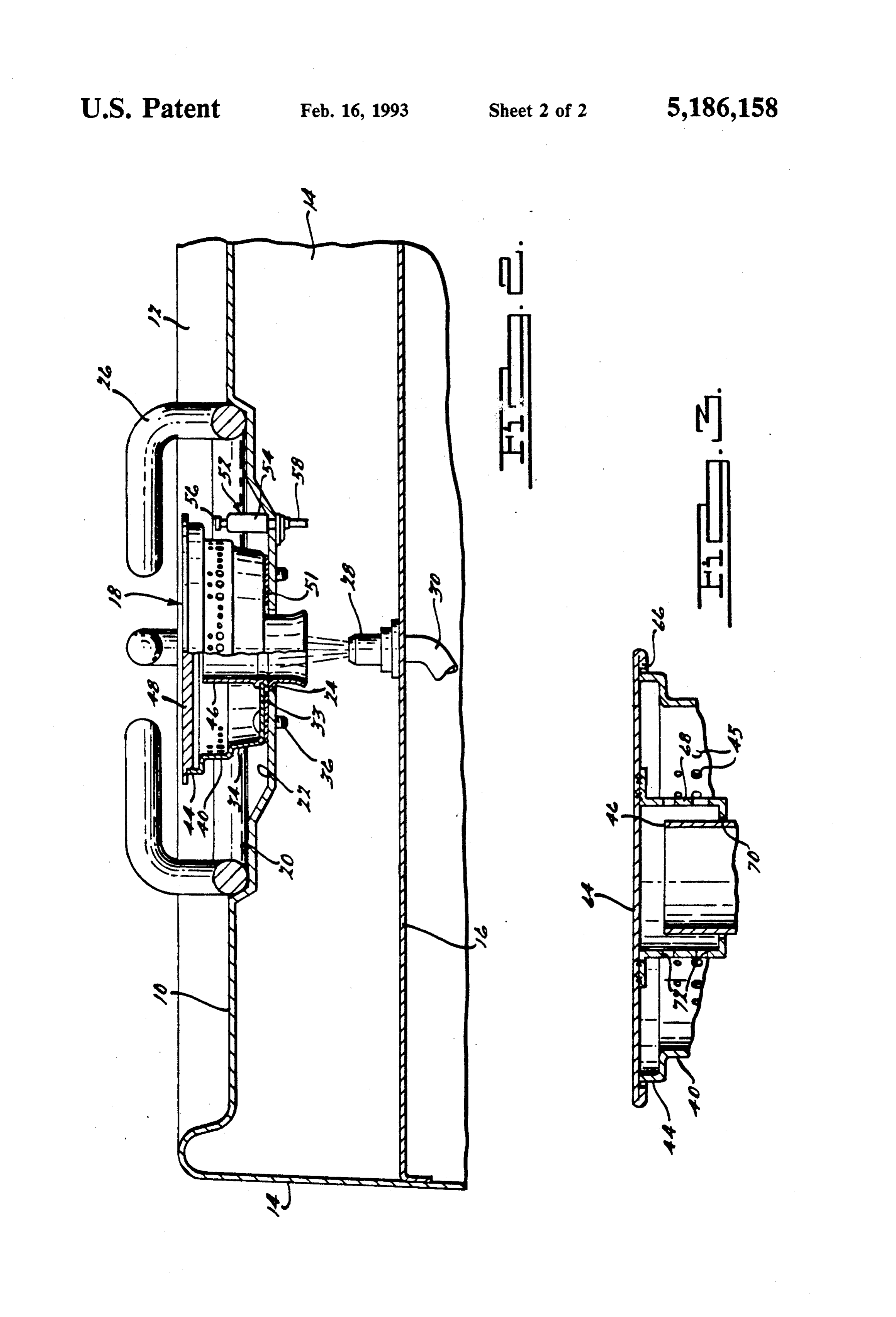
FIG. 1 is a perspective view of a portion of a conven elements.
tional sealed top range incorporating the burner of the If desired, the burner of this invention may be pro present invention but with the trivit removed; vided with an electric igniter 52. In FIG. 2 igniter 52 is FIG. 2 is a is a sectional view taken substantially located outside the burner and comprises an insulating along line 2-2 in FIG. 1; body 54 extending through and affixed to partition 10 FIG. 3 is a is a vertical sectional view of another and an electrode 56 projecting from the upper end embodiment of a burner cap forming part of the present 45 thereof in close proximity to the burner. Electricity is invention; and supplied using conventional circuitry via a wire 58 FIG. 4 is a is a vertical sectional view of the burner of which is connected to electrode 56. When energized, an the present invention showing the ignition in an alterna electric potential is created between electrode 56 and tive location. metal burner body 32 to cause a spark to arc therebe DETAILED DESCRIPTION OF THE 50 tween and ignite the gasous fuel issuing from ports 45. PREFERRED EMBODIMENTS In FIG. 4 igniter 52 is disposed in an alternative position inside burner body 32. This igniter is the same as the one
The range incorporating the burner of the present in FIG. 2 except that the upper end of electrode 56 invention comprises a generally horizontal top partition projects radially outwardly, as at 57, through an open 10 connected via a lip 12 to side walls 14, and an inter 55 ing 60 in body 32 to a point in close proximity to the mediate partition 16 disposed below and generally par body so the necessary electrical arc may be created. To allel to top partition 10 and defining a burner box there prevent a short circuit, electrode portion 57 is disposed between. Most ranges have a plurality of burners, but within an insulating sleeve 62 which also extends because they are usually all the same only one burner, through opening 60, with a slight clearance therebe indicated at 18, will be described herein. At the location tween to provide an additional gaseous fuel passage. of each burner 18 top partition 10 has a first depressed This embodiment of the igniter is described in greater annular recess 20 and a second concentric further de detail in applicant's copending application for U.S. Let pressed annular recess 22 defining an opening 24 ters Patent Ser. No. 255,514, filed Oct. 11, 1988, the through top partition 10. A conventional trivit 26 is disclosure of which is herein incorporated by reference. disposed in recess 20 and burner 18 is disposed in recess 65 Note than in both embodiments cap 48 is of a sufficient 22 overlying opening 24. A conventional gas nozzle 28, diameter, and body 32 is so contoured, that normal supplied by gaseous fuel line 30, is mounted on interme spillage will not hit the igniter (and possibly cause elec diate partition 16 in a position for directing gaseous fuel, trical shorts) or the flame ports.
Page 5
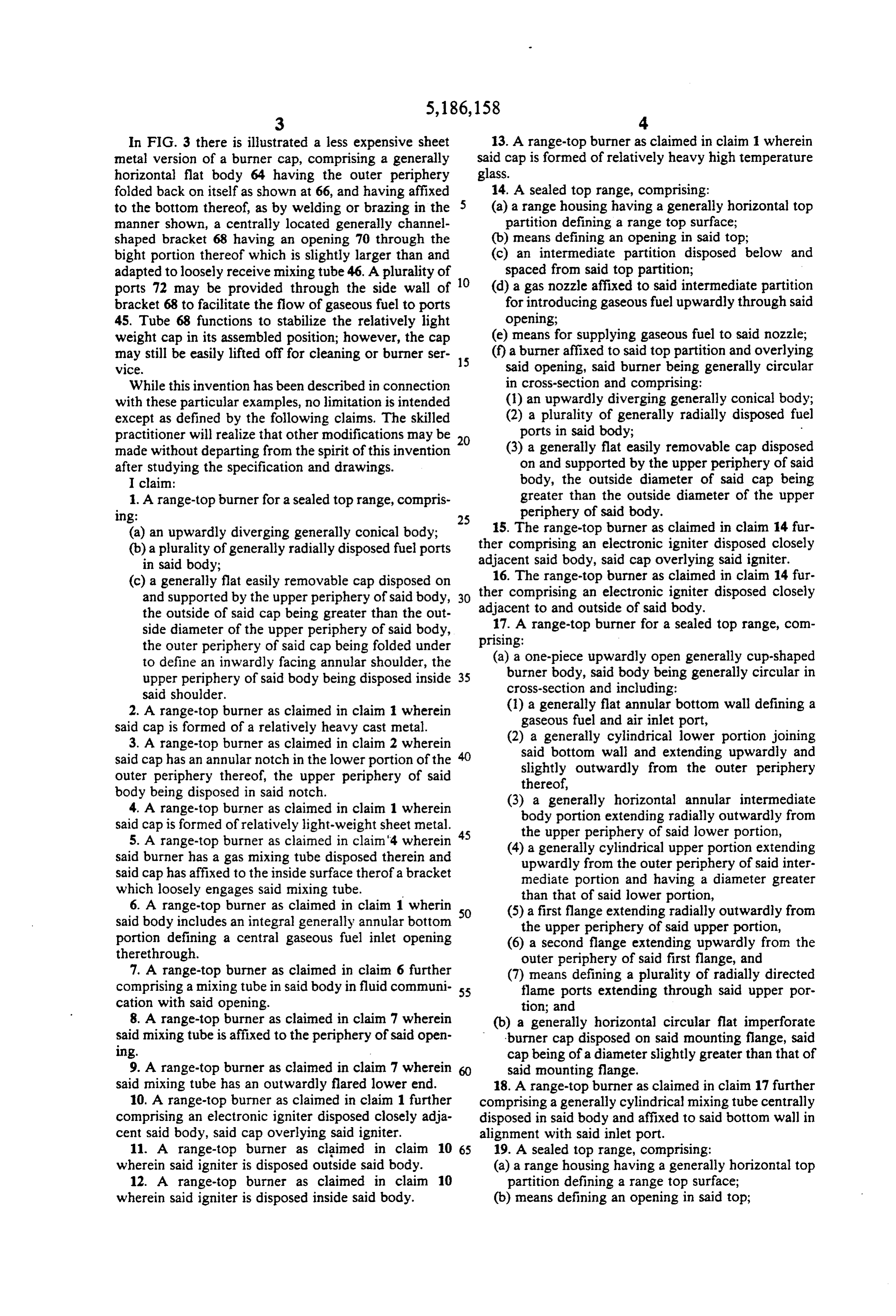
In FIG. 3 there is illustrated a less expensive sheet 13. A range-top burner as claimed in claim 1 wherein metal version of a burner cap, comprising a generally said cap is formed of relatively heavy high temperature horizontal flat body 64 having the outer periphery glass.
folded back on itself as shown at 66, and having affixed 14. A sealed top range, comprising: to the bottom thereof, as by welding or brazing in the (a) a range housing having a generally horizontal top manner shown, a centrally located generally channel partition defining a range top surface; shaped bracket 68 having an opening 70 through the (b) means defining an opening in said top; bight portion thereof which is slightly larger than and (c) an intermediate partition disposed below and adapted to loosely receive mixing tube 46. A plurality of spaced from said top partition; ports 72 may be provided through the side wall of 10 (d) a gas nozzle affixed to said intermediate partition bracket 68 to facilitate the flow of gaseous fuel to ports for introducing gaseous fuel upwardly through said 45. Tube 68 functions to stabilize the relatively light opening;
weight cap in its assembled position; however, the cap (e) means for supplying gaseous fuel to said nozzle; may still be easily lifted off for cleaning or burner ser 15 (f) a burner affixed to said top partition and overlying WC. said opening, said burner being generally circular While this invention has been described in connection in cross-section and comprising: with these particular examples, no limitation is intended (l) an upwardly diverging generally conical body; except as defined by the following claims. The skilled (2) a plurality of generally radially disposed fuel practitioner will realize that other modifications may be 20 ports in said body;
made without departing from the spirit of this invention (3) a generally flat easily removable cap disposed after studying the specification and drawings. on and supported by the upper periphery of said I claim: body, the outside diameter of said cap being 1. A range-top burner for a sealed top range, compris greater than the outside diameter of the upper ling: 25 periphery of said body.
(a) an upwardly diverging generally conical body; 15. The range-top burner as claimed in claim 14 fur (b) a plurality of generally radially disposed fuel ports ther comprising an electronic igniter disposed closely in said body; adjacent said body, said cap overlying said igniter. (c) a generally flat easily removable cap disposed on 16. The range-top burner as claimed in claim 14 fur and supported by the upper periphery of said body, 30 ther comprising an electronic igniter disposed closely the outside of said cap being greater than the out adjacent to and outside of said body.
side diameter of the upper periphery of said body, prising:17. A range-top burner for a sealed top range, com the outer periphery of said cap being folded under (a) a one-piece upwardly open generally cup-shaped to define an inwardly facing annular shoulder, the burner body, said body being generally circular in upper periphery of said body being disposed inside 35 said shoulder. cross-section and including:
2. A range-top burner as claimed in claim 1 wherein (1) a generally flat annular bottom wall defining a said cap is formed of a relatively heavy cast metal. gaseous fuel and air inlet port, 3. A range-top burner as claimed in claim 2 wherein (2) a generally cylindrical lower portion joining said cap has an annular notch in the lower portion of the said bottom wall and extending upwardly and outer periphery thereof, the upper periphery of said slightly outwardly from the outer periphery body being disposed in said notch. thereof, 4. A range-top burner as claimed in claim 1 wherein (3) a generally horizontal annular intermediate said cap is formed of relatively light-weight sheet metal. 45 body portion extending radially outwardly from 5. A range-top burner as claimed in claim"4 wherein the upper periphery of said lower portion, (4) a generally cylindrical upper portion extending said burner has a gas mixing tube disposed therein and upwardly from the outer periphery of said inter said cap has affixed to the inside surface therof a bracket mediate portion and having a diameter greater which loosely engages said mixing tube. than that of said lower portion, 6. A range-top burner as claimed in claim 1 wherin (5) a first flange extending radially outwardly from said body includes an integral generally annular bottom 50 the upper periphery of said upper portion, portion defining a central gaseous fuel inlet opening (6) a second flange extending upwardly from the therethrough. outer periphery of said first flange, and 7. A range-top burner as claimed in claim 6 further (7) means defining a plurality of radially directed comprising a mixing tube in said body in fluid communi 55 flame ports extending through said upper por cation with said opening. tion; and 8. A range-top burner as claimed in claim 7 wherein (b) a generally horizontal circular flat imperforate said mixing tube is affixed to the periphery of said open burner cap disposed on said mounting flange, said ling. cap being of a diameter slightly greater than that of 9. A range-top burner as claimed in claim 7 wherein said mounting flange.
said mixing tube has an outwardly flared lower end. 18. A range-top burner as claimed in claim 17 further 10. A range-top burner as claimed in claim 1 further comprising a generally cylindrical mixing tube centrally comprising an electronic igniter disposed closely adja disposed in said body and affixed to said bottom wall in cent said body, said cap overlying said igniter. alignment with said inlet port. 11. A range-top burner as claimed in claim 10 65 19. A sealed top range, comprising:
wherein said igniter is disposed outside said body. (a) a range housing having a generally horizontal top 12. A range-top burner as claimed in claim 10 partition defining a range top surface; wherein said igniter is disposed inside said body. (b) means defining an opening in said top;
Page 6
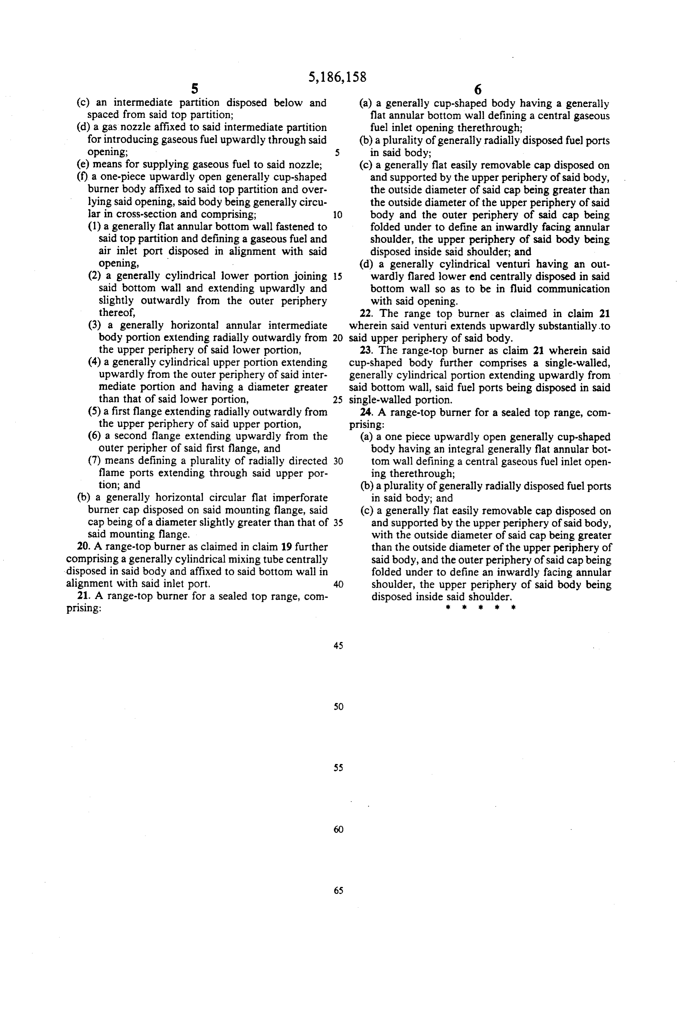
(c) an intermediate partition disposed below and (a) a generally cup-shaped body having a generally spaced from said top partition; flat annular bottom wall defining a central gaseous (d) a gas nozzle affixed to said intermediate partition fuel inlet opening therethrough; for introducing gaseous fuel upwardly through said (b) a plurality of generally radially disposed fuel ports opening; 5 in said body;
(e) means for supplying gaseous fuel to said nozzle; (c) a generally flat easily removable cap disposed on (f) a one-piece upwardly open generally cup-shaped and supported by the upper periphery of said body, burner body affixed to said top partition and over the outside diameter of said cap being greater than lying said opening, said body being generally circu the outside diameter of the upper periphery of said lar in cross-section and comprising; 10 body and the outer periphery of said cap being (1) a generally flat annular bottom wall fastened to folded under to define an inwardly facing annular said top partition and defining a gaseous fuel and shoulder, the upper periphery of said body being air inlet port disposed in alignment with said disposed inside said shoulder; and opening, (d) a generally cylindrical venturi having an out (2) a generally cylindrical lower portion joining 15 wardly flared lower end centrally disposed in said said bottom wall and extending upwardly and bottom wall so as to be in fluid communication slightly outwardly from the outer periphery with said opening.
thereof, 22. The range top burner as claimed in claim 21 (3) a generally horizontal annular intermediate wherein said venturi extends upwardly substantially to body portion extending radially outwardly from 20 said upper periphery of said body.
the upper periphery of said lower portion, 23. The range-top burner as claim 21 wherein said (4) a generally cylindrical upper portion extending cup-shaped body further comprises a single-walled, upwardly from the outer periphery of said inter generally cylindrical portion extending upwardly from mediate portion and having a diameter greater said bottom wall, said fuel ports being disposed in said than that of said lower portion, 25 single-walled portion.
(5) a first flange extending radially outwardly from 24. A range-top burner for a sealed top range, com the upper periphery of said upper portion, prising:
(6) a second flange extending upwardly from the (a) a one piece upwardly open generally cup-shaped outer peripher of said first flange, and body having an integral generally flat annular bot (7) means defining a plurality of radially directed 30 tom wall defining a central gaseous fuel inlet open flame ports extending through said upper por ing therethrough;
tion; and (b) a plurality of generally radially disposed fuel ports (b) a generally horizontal circular flat imperforate in said body; and burner cap disposed on said mounting flange, said (c) a generally flat easily removable cap disposed on cap being of a diameter slightly greater than that of 35 and supported by the upper periphery of said body, said mounting flange. with the outside diameter of said cap being greater 20. A range-top burner as claimed in claim 19 further than the outside diameter of the upper periphery of comprising a generally cylindrical mixing tube centrally said body, and the outer periphery of said cap being disposed in said body and affixed to said bottom wall in folded under to define an inwardly facing annular alignment with said inlet port. 40 shoulder, the upper periphery of said body being 21. A range-top burner for a sealed top range, com disposed inside said shoulder. prising: k . . . .
Page 7
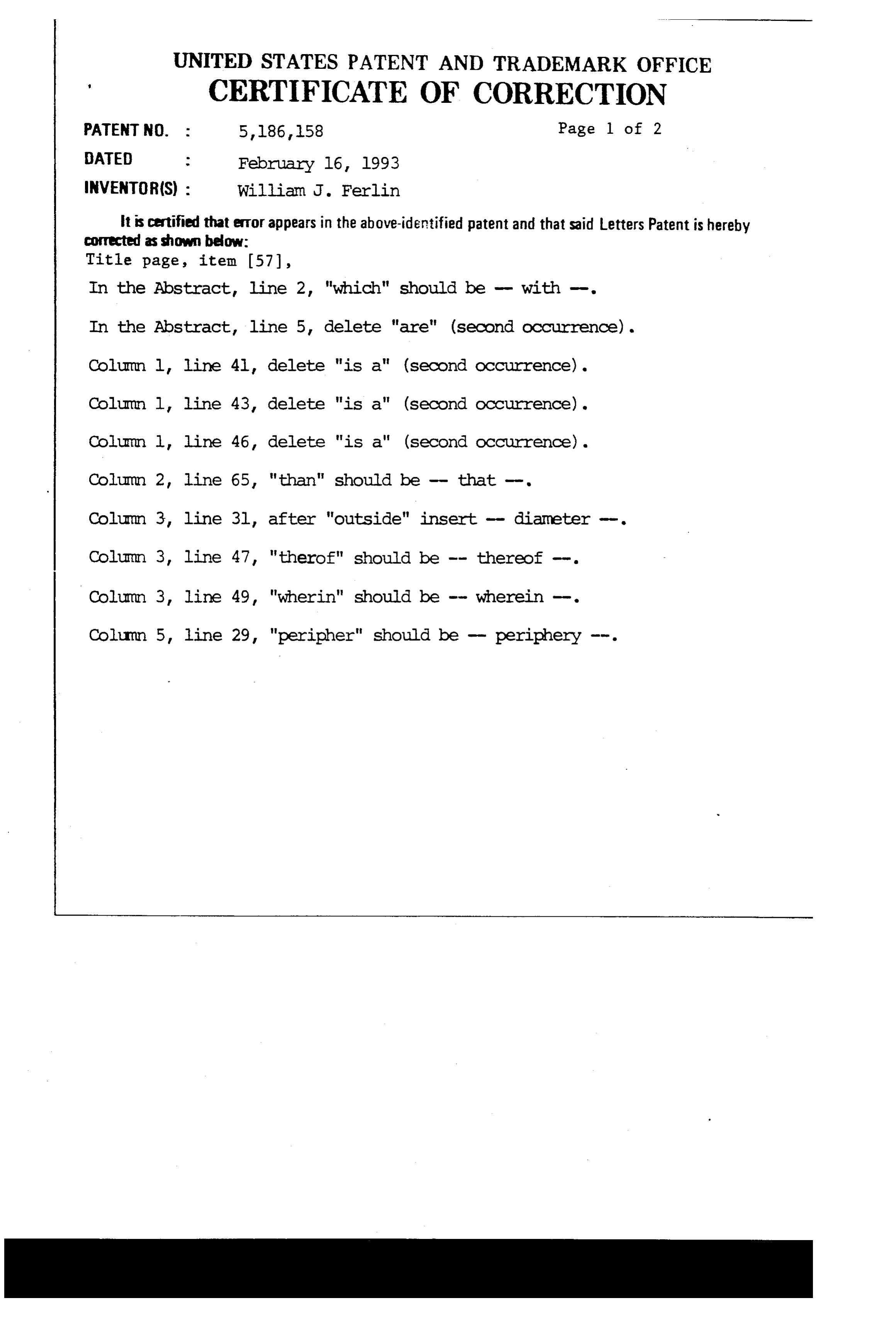
UNITED STATES PATENT AND TRADEMARK OFFICE
s CERTIFICATE OF CORRECTION
PATENT NO. : 5, l86, l58 Page l of 2
INVENTOR(S) : William J. Ferlin it is certified that error appears in the above-identified patent and that said Letters Patent is hereby Corrected as shown below:
Title page, item 57),
In the Abstract, line 2, "which" should be - with -. In the Abstract, line 5, delete "are" (second occurrence). Column l, line 4l delete "is a' (second occurrence). Column l, line 43, delete "is al" (second occurrence). Column l, line 46, delete "is al" (second occurrence). Column 2, line 65 "than" should be - that -. Column 3 line 3l, after "outside" insert - diameter -. Colu in 3, line 47, "therof" should be -- thereof -. Column 3, line 49, "wherin" should be - wherein -. Column 5, line 29, "peripher" should be - periphery --.
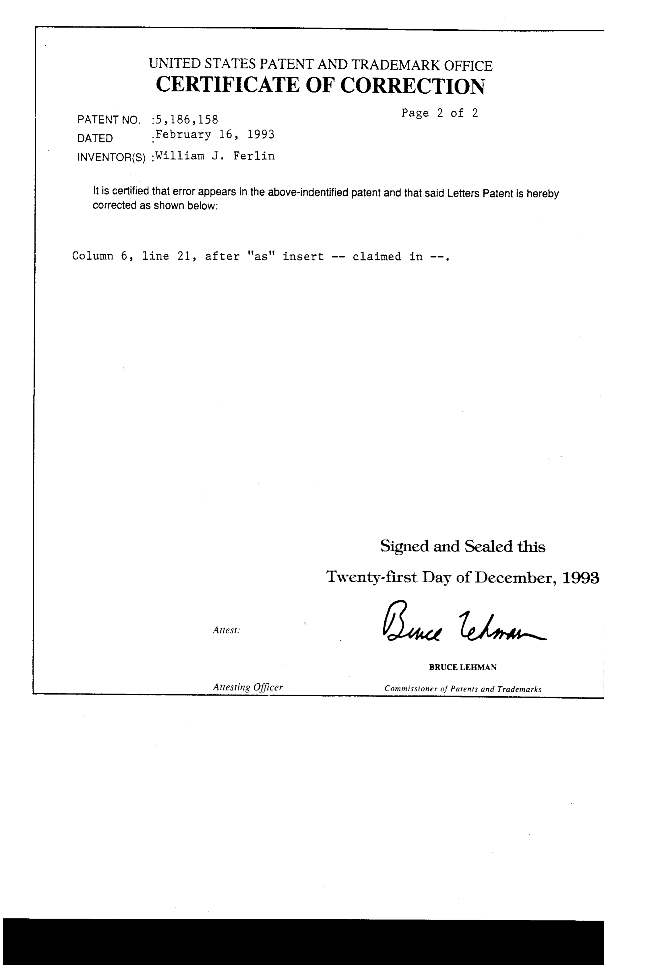
Page 8
UNITED STATES PATENT AND TRADEMARK OFFICE
CERTIFICATE OF CORRECTION
Page 2 of 2
PATENT NO. 5, 186,158 age 4 o
INVENTOR(S) :William J. Ferlin it is certified that error appears in the above-indentified patent and that said Letters Patent is hereby corrected as shown below:
Column 6, line 21, after 'as' insert -- claimed in .
Signed and Sealed this
Twenty-first Day of December, 1993
BRUCE LEHMAN
Attesting Officer Commissioner of Patents and Trademarks
Provenance
- Collection
- Cited prior art
- Original PDF
- patentimages.storage.googleapis.com →
- Filed
- 1990-08-23
- Pages
- 8
- Method
- pdftotext (the PDF's own text layer) + pdftoppm 300dpi page scans
- Source
- Google Patents bibliographic record
- Granted
- 1993-02-16
- Inventors
- William J. Ferlin; Lincoln Brass Works Inc
- Transcribed from
- patentimages.storage.googleapis.com →