patent · US1916983
Gas bubneb
4 July 1933
Page 1
Drawing sheet — no readable text.
Page 2
Patented July 4, 1933 1916,983
UNITED STATES PATENT OFFICE
GARNET. W. McKEE, OF ROCKFORD, ILLINOIS
GAS BUENER,
Application. Alled November 8, 1928. Serial No. 318,079.
The present invention relates to improve along
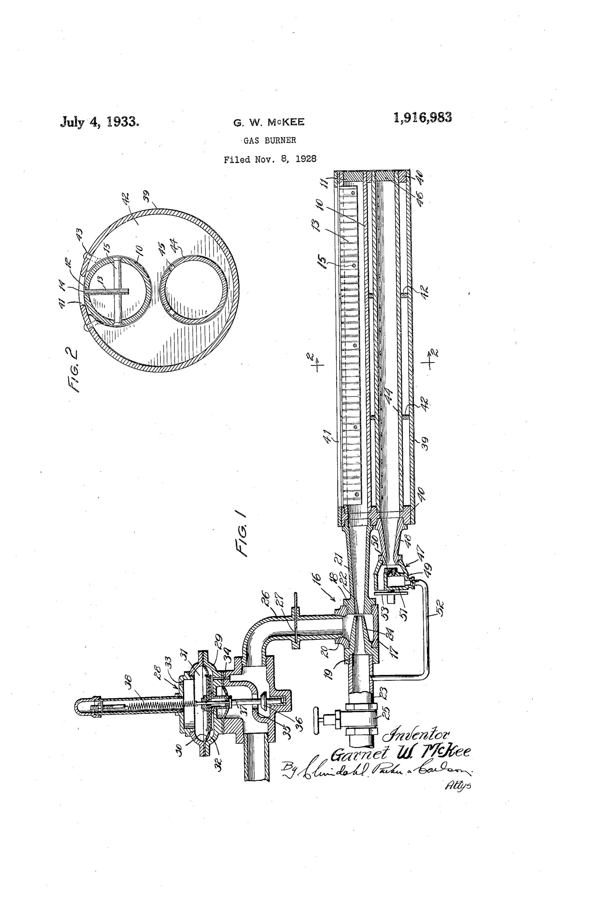
Fig. 2 is a transverse sectional view taken
ments in gas burners. .
In certain cases where gas burners are often While the invention is susceptible of va used, as in core ovens, japanning ovens and rious modifications and alternative construc 5 drying ovens, fumes from the work serious tions, I have shown in the drawing and will 55 lyinterfere with combustion. The primary herein describe in detail the preferred em object of the present invention therefore re. bodiment, not théréby but it is to be understood that I do intend to limit the invention to sides in the provision in a gas burner of novel means for protecting the flame against the specific form disclosed, but intend to 60 10 surrounding fumes or inert gases so as to cover al modifications and alternative con permit free and efficient combustion, structions falling within the spirit and scope of the invention as expressed in the appended.
A more specific object resides in the pro claims.
visionin a gas burner of novel means for sup; Ovens having relatively large surfaces, plying secondary air of combustion about such 15 the flame so as to envelop the flame in an oxi as those referred to in the foregoing, are 66 often provided with gas burners adapted to dizing atmosphere, and hence to keep fumes ive a ribbon flame. While the invention is and gases which would interfere with com- gnot limited thereto, it is particularly appli bustion away from the flame, ) An important object resides in the pro cable to burners of this type, and in, the ac 20 vision in a burner of the foregoing charac companying drawings is illustrated in con ter of novel means for automatically control nection with one form thereof. ling the supply of secondary air in propor Referring more specifically to the drawing, tion to the supply of the primary fuel mix the burner constituting the exemplary em ture so as to maintain a predetermined air bodiment of the invention comprises an elon gas ratio. Y ? gated hollow burner member 10 preferably Still another object is to provide a novel tubular in form and tightly closed at one gas burner in which the supply of primary end in any suitable manner, as by means of air, of gas, and of secondary air, in a given a10,plug 11. Formed in one side of the tube proportion is under the control of a single preferably in a milling operation, and terminating slightly short of the ends there
A more specific object resides in the pro of, is a narrow longitudinal slot 12. A suit able strip 13 which is corrugated laterally vision of novel means for supplying second and which is substantially coextensive in ary air in which part of the secondary, air length with the slot 12 is fitted tightly there 35 is taken from the primary air line, and in in, and with the sides of the slot defines a 85 which the rest of the secondary air is induced series of closely spaced ports or jet passages
14 longitudinally of the tube 10. Gas from
Various general objects of the invention re the tube 10 is adapted side in the provision of a novel gas burner passages 14 for ignitiontoinpass the through these form of a rib 90 of the foregoing character which is rigid, bon flame.
sturdy, simple and inexpensive in construc To prevent the sides of the slot 12 from tion, which is safe and efficient in operation, moving and in which there is an equal distribution ripheralaway from the strip 13, through pe expansion of the tube 10, a plural of the fuel mixture and the secondary air. ity of rivets 15 extend through the tube at Further objects and advantages will be come apparent as the description proceeds. spaced points and laterally of the slot.
To hold the strip 13 positively against dis
In the accompanying drawing, Fig. 1 is a placement in the slot 12, it is made of a width sectional view, partially diagrammatical in to extend a substantial distance into the tube character, of a gas burner embodying the 10. Preferably, the strip 13 extends a short OO 50 features of my invention. though substantial distance beyond the cen
Page 3
ter of the tube. The rivets 15 extend through tion with the slot 12. Disposed in longitu the strip 13, and serve to hold the latter, in dinally spaced relation in the tube 39 are a position. The strip 13 also serves to divide plurality of transverse, suitably recessed cast the flow of gas in the tube 10 to the passages ings 42. These castings 42, together with 14, thereby improving the distribution of the the end plugs 40 serve to hold the tube 10 fuel mixture. in position, and the margins of the slot 41 are The burner tube 10 may be connected to secured thereto, as by cap screws 43, to pre any suitable source of fuel, and in the present vent the margins from moving away from the instance is connected to a mixing and pro tube 10 due to peripheral expansion of the O portioning device 16, preferably in the form tube 39. 75 of a Venturi suction T. More specifically, Means is provided for supplying second the device 16 comprises a casing 17 having an ary air of combustion to the tube 39 for outlet opening 18 and inlet openings 19 and passage about the tube 10 to the slot 41, and 20. for automatically controlling the supply of s Secured in the opening 18 is a suitable secondary air in accordance with the supply 80 expanding nozzle 21 having an inlet port 22 of gas and primary air to the tube 10. In the in the casing 17 and being connected to the present instance, this raeans comprises a tube open end of the tube 10. 44 extending in parallel relation to the tube An air line 23, adapted to be connected to 10 through the tube 39, and having a plurality a suitable source of air under pressure (not of apertures 45 along its length. Of the tube shown), is connected to an inlet nozzle 24 44, one end is closed in any suitable manner, secured in the opening 19. The nozzle 24 is as by a plug 46, and the other end extends in alignment with the nozzle 21, and opens outwardly through one of the plugs 40, and directly in front of the port 22. Interposed is provided with an injector 47. The injector in the line 23 is a suitable regulating valve 47 comprises a Venturitube 48, the discharge
end of which is connected to the tube 44, and
A gas line 26 adapted to be connected to the inlet end of which is provided with a cas a suitable source (not shown) of fuel is con ing 49 opening to the atmosphere. Disposed nected to the opening 20. Interposed in the in the casing 49 and having a restricted dis line 26 is a suitable adjustable orifice 27 and charge orifice 50 opening to the Venturi tube 95 a suitable zero governor 28. Preferably, the 48 is an air nozzle 51 connected through a zero governor 28 is of standard construction, small by-pass line 52 to the primary air line and comprises a casing 29 and a diaphragm 23 at the discharge side of the valve 25. An 30 dividing the casing into chambers 31 and adjustable shutter 53 is provided to regulate 00 35 32. The chamber 31 opens through a suitable the opening from the atmosphere to the cas port 33 to the atmosphere, and the chamber ing 49. It will be evident that the air from 32 opens through a suitable vent passage 34 the line 52 will be proportional to the air to the line 26 at the outlet side of the gov flowing to the tube 10, and that the air in ernor. Interposed in the gas line 26 is a suit duced from the atmosphere will be propor 40 able valve comprising a seat 35 and a valve tional to the discharge from the orifice 50.
member 36 connected by a stem 37 to the In operation, the burner is controlled by diaphragm 30. A spring 38 connected at one means of the regulating valve 25 which in end to the diaphragm 30 and adjustably an the present disclosure controls the supply of chored at the other end in the casing 29 tends air. Primary air entering the device 16 in 45 to flex the diaphragm in a direction to close the valve.
duces a proportional flow of gas from the line 0.
26. This proportion may be varied by ad
Air under pressure passes from the inlet justing the orifice 27. Preferably the pro nozzle 24 to the expanding nozzle 21, and in portion is slightly less than that necessary so doing creates a vacuum which serves to 50 induce a flow of gas proportional to the flow to effect complete combustion. The resulting mixture passes to the tube 10 from which of air. The ratio may be adjusted by means it is discharged through the passages 14 for of the orifice 27, and the amount of the mix ignition. Secondary air in direct proportion ture may be adjusted by the valve 25. to the fuel mixture is supplied to the tube
in certain instances, surrounding fumes 44 by the injector 47. Most of the secondary and/or inert gases tend to interfere seriously air is induced from the atmosphere, and the 120 with combustion. One of the primary objects proportion of secondary air can be varied of the invention resides in the provision of by means of the shutter 53. The secondary means for protecting the burner from such air is discharged from the tube 44 to the tube influences. To this end, the burner tube 10
GO is mounted in a relatively large enclosing 39 from which it passes about the tube 10 to the slot 41. The secondary air is suffi member 39 which preferably is tubular in cient to complete combustion, and being dis form and which is closed at the ends by suit charged at opposite sides of the passages 14 able means, such as plugs 40. The tube 39 is tends to envelope the flame and to prevent formed with an elongated slot 41 substan surrounding fumes or gases from interfering
tially coextensive in length and in registra with combustion. 30
Page 4
Thus, the burner involves a supply of pri the supply of the mixture for supplying mary air, secondary air and gas, with the proportional volume of secondary air to said casing for discharge through said passage, amounts of secondary air and gas controlled by the amount of primary air and always. and means for adjusting the proportion o 5 directly proportional thereto. The burner the secondary air to the mixture. O pressure is derived from the primary air pres: 5. A gas burner comprising, in combina: sure. The amount of secondary air supplied tion, a burner element, a casing enclosing said is controlled by the amount of primary air. element and having an opening, said element The amount of gas supplied is controlled by having means for directing a flame through O , the amount of primary air. The flow of gas said opening, an injector connected to said is and secondary air is energized by the primary element, said injector having a gas suction air. This permits of a single control which regulating is embodied in the valve 25.
inlet and an air pressure inlet, means for the supply of air to said injector,
I claim as my invention: and an injector for supplying air to said 5 1. A gas burner comprising, in combina casing, said last mentioned injector being tion, an enclosed casing having an opening, responsive to the air flow to said first men a burner element disposed in said casing and tioned injector.
having means for defining a gas flame in reg 6. A gas burner comprising, in combina istration with said opening, a proportioning tion, an elongated outer casing formed with 2 device connected to said element, means for a longitudinal opening in one side, an elon supplying a fluid under pressure to said de gated burner tube in said casing, said tube vice as an inducing fluid, means for supply being formed longitudinally with means in ing another fluid by induction to said device, registration with said opening for defining and means for supplying secondary air to said a flame, and being spaced from the sides of 90 25 casing, said last mentioned means being re said opening to define secondary air discharge sponsive to the pressure of said inducing means at opposite sides of said first men fluid. tioned means, an elongated air tube in said 2. A gas burner comprising, in combina casing substantially parallel to said burner tion, a burner tube having means for defin tube, said air tube being perforated to dis 30 ing a longitudinalflame, aclosed casing hav charge into said casing, one end of said air ing an opening in registration with said first tube being open to the atmosphere, and means mentioned means, a perforated air tube in said casing, a proportioning device having ????? supplying
a fuel mixture to said burner a pressure inlet and a suction inlet for Sup 7. A gas burner comprising, in combina 100 plying a mixture of air and gas to said tion, an elongated outer casing formed with burner tube, an injector for supplying air a longitudinal opening in one side, headers from the atmosphere to said air tube, said closing the ends of said casing, an elongated injector being connected to the pressure inlet burner tube in said casing with its ends an of said proportioning device. chored in said headers, said tube being s 3. A gasburner comprising, in combina formed longitudinally with means in regis 0. tion, a burner element having means for de tration with said opening for defining a fining a gas flame, means for supplying a flame, and being spaced from the sides of mixture of air and gas under pressure to said opening to define secondary air dis said element, and means for automatically charge means at opposite sides of said first O 45 supplying secondary air in proportion to mentioned means, an elongated air tube in said mixture about said element at said first said casing substantially parallel to said mentioned means, said last mentioned means burner tube and anchored at its ends in said including an induction passage open to the headers, said air tube being perforated lon atmosphere and a jet nozzle opening into gitudinally, intermediate spaced transverse 5 said passage and longitudinally thereof, and supports in said casing for said tubes, one is connected to said second mentioned means end of said air tube being open to the atmos for a supply of inducing pressure fluid. phere, and means for supplying fuel mix 4. A gasburner comprising, in combina ture to said burner tube.
tion, an outer casing having an opening, a 8. A gas burner comprising, in combina 2 burner element mounted in said casing and tion, a casing having an air outlet, a burner having means for defining a flame, said means having a fuel outlet in registration with said being in registration with said opening to air outlet, a proportioning Venturi fuel direct the flame therethrough, the edge of mixer connected to said burner, an induced said opening being spaced from said element fluid line connected to said mixer, means in 25 60 to define a secondary air discharge passage said line for governing the pressure of the adjacent said means, adjustable means for induced fluid, an adjustable orifice in said supplying a variable volume of a propor line between said means and said mixer for tioned primary mixture of gas and air to: regulating the proportion of gas and air, said element, means for adjusting the pro an inducing fluidline connected to said mixer, a volume control valve in said last men O 65 portions of the mixture, means responsive to
Page 5
tioned line, an air injector connected to said to said first mentioned line at the discharge casing and opening to the atmosphere, ad side of said valve.
justable means for controlling the opening to 13. A gas burner comprising, in combina the atmosphere, said injector including a jet tion, a burner element, a proportioning de 5 nozzle, and a pressure line connecting said vice connected to said element, means for 70 nozzle to said last mentioned line at a point supplying a fluid under pressure to said de between said volume control valve and said vice as an inducing fluid, said means includ mixer. 0 v a s ing a manual regulating valve for adjusting 9. A gas burner comprising, in combina the supply of said fluid to said device, means 75 10 tion, a casing having an opening, a burner for supplying another fluid at a substantially mounted in said casing and having fuel dis constant pressure by induction to said device charge means in registration with said open for proportional mixture with said first men ing, a proportioning fuel mixer for supply tioned fluid, and means for supplying sec ing a mixture of gas and air to said burner, ondary air to said burner element, said last 15 a Venturi injector for supplying air to said mentioned means being automatically respon casing, said injector including a chamber sive to the pressure of said inducing fluid at open to the atmosphere and a nozzle for dis a point between the discharge side of said charging a jet of fluid under pressure to in valve and said device.
duce a proportionate flow of air from the 14. A gas burner comprising, in combina 85 atmosphere through said injector into said tion, an elongated outer casing formed with casing, and means for supplying a fluid un alongitudinal opening in one side, end plugs der pressure to said nozzle. closing the ends of said casing, an elongated 10. A gas burner comprising, in combina burner tube extending longitudinally tion, a casing having an opening therein, a through said casing and eccentrically there burner mounted in said casing and having of and having its ends anchored in said plugs, fuel discharge means in registration with said opening, an expanding cone mounted on said tube being formed longitudinally with and discharging to said casing, an air cham definingina registration means flame, and with said opening for being spaced from the ber communicating with the inlet of said sides of said opening to define cone and with the atmosphere, an adjustable discharge passages at opposite secondary air sides of said 95 valve for controlling the communication of first mentioned means, an elongated air tube said chamber with the atmosphere, an in extending through said casing in substantial jector nozzle mounted to direct a jet of fluid ly parallel relation to said burner tube and under pressure axially into the inlet end of anchored at its ends in said plugs, said air 100 said cone, a fluid pressure supply line con tube being perforated longitudinally, spaced , nected to said nozzle, and means for supply intermediate transverse disks in said casing, ing a fuel mixture to said burner. said disks fitting the inner perphery of said 11. A gas burner comprising, in combina casing tion, a burner element, means for supplying throughand which being formed with apertures said tubes extend, means for 05 primary air under pressure to said element, securing the marginal portions of said cas said means including a volume control valve ing along said opening to said disks, means means responsive to the primary air supplied for supplying fuel to said burner tube, and for automatically supplying a proportional means volume of gas to said element, and means 15. Aforgassupplyingburner air to said air tube.
comprising, in combina 0.
responsive to the primary air supplied for tion, an elongated outer casing formed with ". automatically supplying a proportional vol a longitudinal opening in one side, an elon ume of secondary air to said element, where gated burner tube extending longitudinally by said valve constitutes a single member said casing and eccentrically thereof, said for proportionately controlling the supply of in tube being formed longitudinally with means i 5 50 primary air, gas and secondary air. in registration with said opening for defin 12. A gas burner comprising, in combina ing a flame, and being spaced from the sides tion, a burner element having means for dis of said opening to define secondary air dis charging a fuel mixture, an air and gas mix charge passages at opposite sides of said first ing chamber connected to said element, a gas mentioned means, an elongated air tube in 0. chamber connected to said mixing chamber, said casing in substantially parallel relation means for supplying gas at a constant pres to said burner tube, said air tube being per sure to said gas chamber, a nozzle in said gas forated longitudinally, means for supplying chamber and adapted to discharge into said fuel to said burner tube, and means for sup mixing chamber, anair line including a con plying air to said air tube. trol valve for supplying air under pressure In testimony whereof; I have hereunto af to said nozzle, and means for supplying sec fixed my signature.
ondary air to said element, said last men GARNET W. McKEE. tioned means including an air line connected
Provenance
- Collection
- Cited prior art
- Original PDF
- patentimages.storage.googleapis.com →
- Pages
- 5
- Method
- pdftotext (the PDF's own text layer) + pdftoppm 300dpi page scans
- Source
- Google Patents bibliographic record
- Granted
- 1933-07-04
- Transcribed from
- patentimages.storage.googleapis.com →