patent · US4674698
Left-right retrieve spin cast reel
23 June 1987
Page 1 — bibliographic record
United States Patent (19) 11) Patent Number: 4,674,698 Carpenter 45) Date of Patent: Jun. 23, 1987 54 LEFT-RIGHT RETRIEVE SPIN CAST REEL Primary Examiner-Billy S. Taylor (75) Inventor: Robert L. Carpenter, Tulsa, Okla. Attorney,
Mason & Agent,
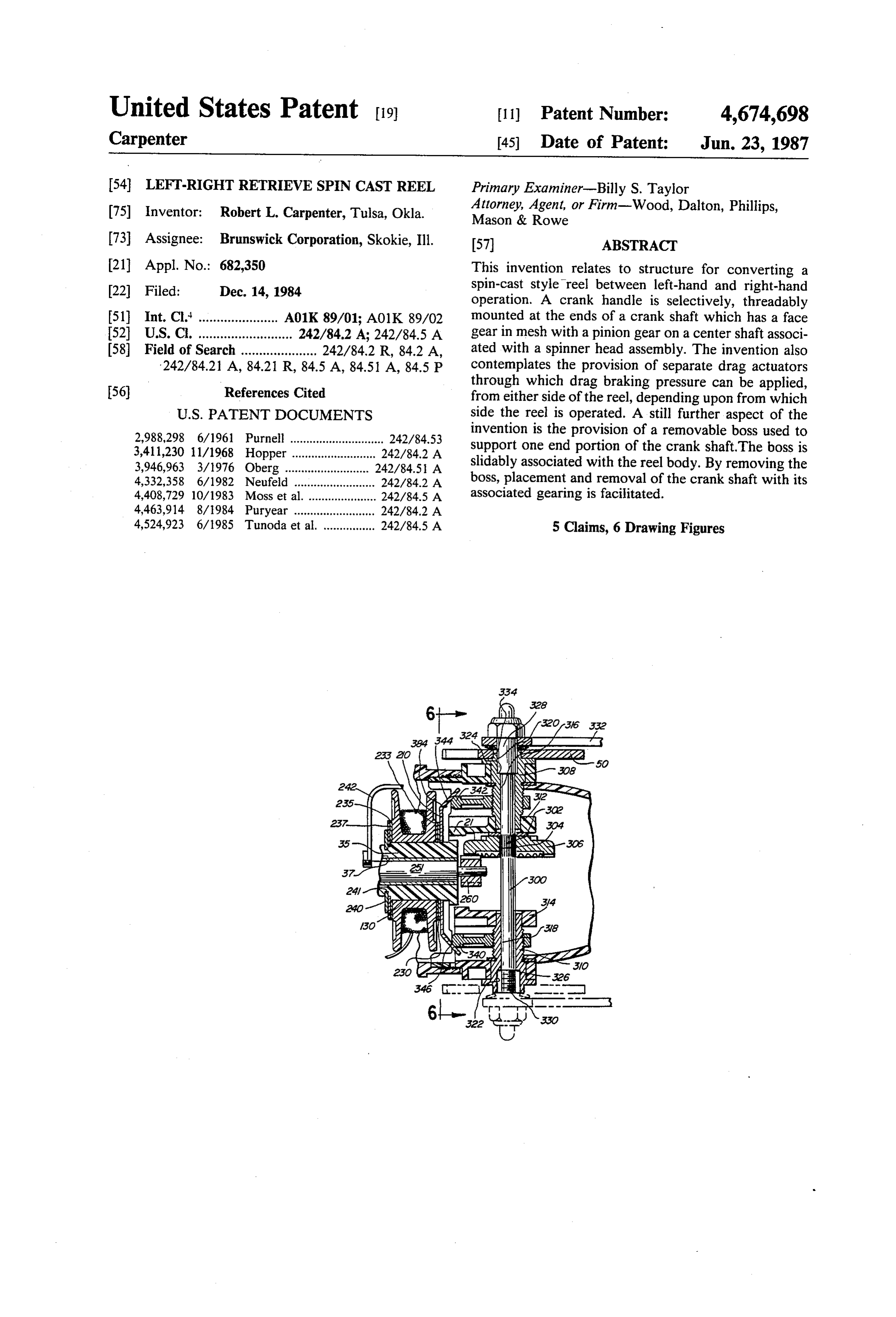
Rowe or Firm-Wood, Dalton, Phillips, 73 Assignee: Brunswick Corporation, Skokie, Ill. 57 ABSTRACT (21) Appl. No.: 682,350 This invention relates to structure for converting a 22 Filed: Dec. 14, 1984 spin-cast style reel between left-hand and right-hand operation. A crank handle is selectively, threadably 51 Int. Cl. .......... ... A01K 89/01; A01K 89/02 mounted at the ends of a crank shaft which has a face 52 U.S. C. ................ ... 22643A242,845A gear in mesh with a pinion gear on a center shaft associ 58) Field of Search ..................... 242/842 R, 84.2 A, ated with a spinner head assembly. The invention also 242/84.21 A, 84.21 R, 84.5 A, 84.51 A, 84.5 P contemplates the provision of separate drag actuators through which drag braking pressure can be applied, 56) - References Cited from either side of the reel, depending upon from which
invention is the provision of a removable boss used to
OPPCI .M.E.
. . . . .. . . . . . . . . . . . . .. . . . . . w support one end portion s of the crank shaft.The boss is 3,946,963 3/1976 Oberg ....... ... 242/84.5. A slidably associated with the reel body. By removing the 4,332,358 6/1982 Neufeld ........ - - - - 242/84.2 A boss, placement and removal -- - of the crank shaft with its 4,408,729 10/1983 Moss et al. .... ... 242/84.5 A associated gearing is facilitated.
4,524,923 6/1985 Tunoda et al. ................ 242/84.5 A 5 Claims, 6 Drawing Figures
SNS
Page 2
Drawing sheet — no readable text.
Page 3
Drawing sheet — no readable text.
Page 4
merely unthreading the crank handle from one side and
LEFT-RGHT RETRIEVE SPIN CAST REEL replacing it on the opposite side of the reel. It is also an objective of the invention to afford
BACKGROUND OF THE INVENTION smooth drag and a drag transition through a mechanism 1. Field of the Invention that is operable selectively from either side of the hous This invention relates to spin cast style fishing reels ing depending upon which side the crank handle is and, more particularly, to a reel that is convertible be mounted. To accomplish this end, the drag mechanism tween the left-hand and right-hand operating modes. has a drag plate that bears upon a line-carrying spool 2. Background Art rotatably associated with the reel body. Laterally Conventional above-the-rod spin cast style fishing 10 spaced cam surfaces are formed integrally with the drag reels accommodate either left-handed or right-handed plate and are independently operated upon by separate operators, depending on which side of the reel the crank actuators associated with posts. The posts extend handle is carried. The conventional above the rod spin through the housing, on opposite sides thereof, and are cast construction therefore has had serious drawbacks rotatably mounted therewithin. Rotation of either post, from the standpoint of both manufacturing and distribu 15 preferably accomplished through an externally manipu tion. Parts must be fabricated which are adaptable to the lated drag star wheel, moves each actuator along its reels of only one operating mode. In stocking supplies respective cam surface to either increase or decrease a of reels for sale, a distributor must attempt to anticipate drag braking pressure on the spool. The drag wheel is the demand for reels operated by left and right-handed moved from one side to the other with the crank handle
to effect conversion.
It is known to make spinning reels that are convert It is a further object of the invention to facilitate ible between left-hand and right-hand operation. An assembly of a crank shaft in a reel with selective right exemplary structure is shown in U.S. Pat. No. 4,196,867, hand and left-hand operating capability. A first boss is to Miller. In Miller, the screw connected crank handle fixed to the reel body and has a bore to receive the can be separated and reconnected on the opposite side 25 crank of the reel. However, structurally the above the rod to theshaft. A second boss is adjustable slidably relative spin cast reel does not lend itself to incorporation of this second reel body and can be separated therefrom. The structure. First of all the drag assembly in Miller is rear the boreboss is positionable to align a bore therein with on the first boss so that the bosses coopera mounted and is not associated with the crank mecha tively support the crank shaft. The removable second nism. Consequently, conversion between left-hand and 30 boss permits access to a pinion gear on the center shaft right-hand operation modes in Miller does not require for separation of the pinion gear and removal of the an adaptation of the drag mechanism as is required in center shaft. This in turn facilitates placement and re the above the rod spin cast style reels.
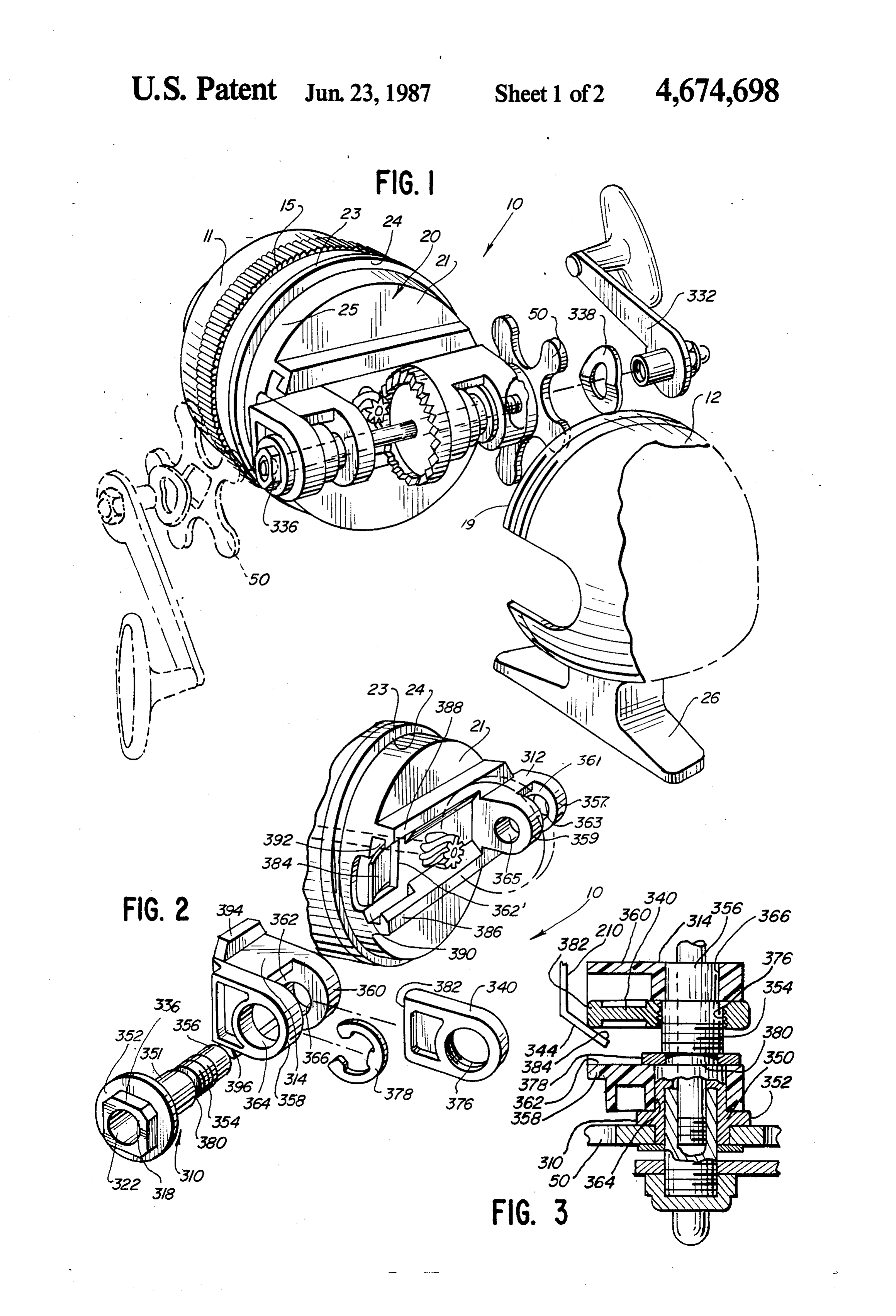
Under-the-rod spin cast style reels such as shown in moval of the crankshaft with its associated gear mecha Neufeld U.S. Pat. No. 4,368,856 have an interchange 35 nism that is in mesh with the pinion. able left-right crank handle structure made possible in BRIEF DESCRIPTION OF THE DRAWINGS part because there is no star wheel drag adjustment coaxial with the crank shaft. FIG. 1 is an exploded, perspective view of a spin cast Further, the axis of the crankshaft in most above the reel incorporating a preferred embodiment of the inven rod spin cast reels normally intersects the center shaft tion;
axis. Extension of the crankshaft across the width of the FIG. 2 is a partial, exploded, perspective view of the reel to allow conversion is precluded because the crank drag mechanism and a removable support boss for the shaft would interfere with the operation of the center crank shaft of the reel of FIG. 1;
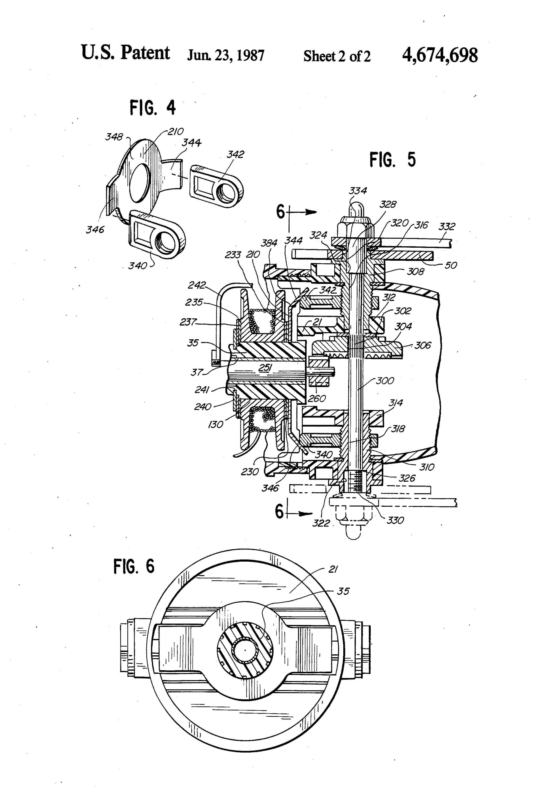
shaft, directed rearwardly beyond the axis of the crank FIG. 3 is a fragmentary, sectional view of the drag shaft for engagement by a rear mounted thumb button 45 mechanism on one side of the reel in FIGS. 1 and 2. or the like. FIG. 4 is a perspective view showing the relative The present invention is specifically directed to over alignment between separate drag actuators and a drag coming the above enumerated problems in a novel and plate associated with the drag mechanism of the reel of simple manner. FIGS. 1 and 2;
SUMMARY OF THE INVENTION 50 FIG. 5 is an overhead, fragmentary, sectional view of the structure for converting between left-hand and
The invention comprehends conversion between right-hand operation and a preferred drag mechanism left-hand and right-hand operation in a spin cast reel of according to the present invention; the type having a housing with a reel body therein and FIG. 6 is a sectional view of the reel along line 6-6 a center shaft extending through the reel body and 55 of FIG. 5.
carrying a spinner head. According to the invention, a DESCRIPTION OF THE PREFERRED crank handle can be mounted selectively at either end of EMBODIMENT a crank shaft, which is operable to rotate the center shaft and in turn the spinner head. The axis of the center FIGS. 1 and 2 depict a conventional spin cast style shaft may be slightly offset from the axis of the crank fishing reel at 10, to which the present invention is shaft or may intersect with the axis of the center shaft. adaptable. The reel 10 comprises a two-part, front, cup In the case where the crank shaft and center shaft are shaped cover 11 and a rear, cup-shaped cover 12 which offset, the center shaft extends beyond the axis of the captively surround a reel body 20 and encase the oper crank shaft and is operatively engaged by a thumb but ating mechanism associated therewith. The reel body 20 ton at the rear of the housing to shift the center shaft. 65 has a deck plate 21 with a forwardly facing surface on Preferably the crank shaft has opposite, threaded ends an enlarged flange 23 which bears on a shoulder (not to accept an operating crank handle so that conversion shown) defined by an annular undercut on the inside of between left-hand and right-hand operation involves the front cover 11. The rearwardly facing surface 24 of
Page 5
the flange 23 defines an offset collar 25 which seats in drag plate 210. The outer legs 357 and 358 of the bosses the mouth of the rear cover 12 as the forwardly directed 312, 314, respectively, have enlarged bores 363, 364 edge 19 of the rear cover 12 abuts the surface 24 of the while inner legs 359, 360 of the bosses have reduced flange. The front cover 11 has an internal thread which diameter bores 365,366. The posts 308,310 each have a threads on an external thread of the rear cover 12. The 5 through bore 316, 318 conforming closely to the diame front and rear covers engage, one within the other, to ter of the crank shaft 300. Each post 308, 310 has a establish connection and define a unitary reel structure. cylindrical body portion 350 divided into six parts, a The front cover 11 has a knurled outer gripping portion square or other non-round attaching portion 336, a 15 which facilitates grasping for effecting relative rota radial flange 352, a large diameter bearing portion 351, tion between the front and rear covers. The reel is an O an undercut 380, a threaded portion 354 and a reduced above the rod type and is mountable to a fishing rod diameter bearing or guide portion 356. The external through a mounting foot 26 formed integrally with the diameter of the large bearing portion 351 and the re rear cover 12. duced diameter portion 356 rotatably mate with the The basic reel operation can be best described with internal diameters of the enlarged bores 363, 364 and reference to FIGS. 1, 2 and 5. The reel body 20 has an 5 reduced diameter bores 365, 366 of the bosses 312,314, integrally formed central hub 35 extending from the respectively.
deck plate 21 associated with the reel body 20. The hub To assemble the crank shaft 300 and face gear 306 35 carries, in succession forwardly from the deck plate, with the deck plate, the one end of the crank shaft is a drag plate 210, back spool washer 230, back flat drag threaded through bore 365 in leg 359, through bore 376 washer 233, line carrying spool assembly 130, front flat 20 in actuator 340 and bore 363 in leg 357 and face gear 306 drag washer 235 and front spool washer 237, all of is loosely meshed with the pinion gear 360 whereupon which are backed against retainer clip 240, resiliently the post 308 is threaded on the end of the crankshaft and bound in an annular slot 241 in the hub 35. assembled with the fixed boss 312 by inserting the re A center shaft 251 is journalled for rotation in a bore duced diameter portion 356 through the bore 363 in the 37 directed centrally of and longitudinally through the 25 leg 357 into the threaded bore 376 in the actuator 340, hub 35. The forward region of the center shaft carries a which actuator is held in the opening 362 between the spinner head assembly 242, which, through its associ legs 357, 359 until the threaded portion 354 can be ated mechanism (not shown), in a first mode, allows threaded into the threaded bore. When the post has payout of fishing line and in a second mode, directs line been threaded into actuator 340 enough, the reduced onto the spool 130 upon rotation of the center shaft 251. 30 diameter portion 356 is seated in bore 365 and large A better understanding of the operation of the spinner diameter portion 351 is seated in bore 363 and a C head assembly 242 can be gained from a review of U.S. shaped spring clip 378 is snapped into undercut 380 Pat. No. 4,408,729, to Moss et al, which depicts a like between the threaded portion 354 and the large diame spinner head and describes the same in detail. Rotation ter portion 351 against one face of leg 357. The clip 378 of a crank handle 332 rotates the crank shaft 300, gear 35 and flange 352 trap the post 308 in the boss 312 for 306, pinion gear 260, centershaft 251 and spinner head rotation about its axis. The actuator 340 is trapped be 242 for winding line on the spool 130. tween the top and bottom walls of the slot 362 so that as According to the invention, the crank shaft 300 ex the post rotates the actuator moves axially of the post. tends laterally between the sides of the reel. The axis of With the removable boss 314 assembled on the deck the crankshaft 300 is shows intersecting the axis of the 40 plate 21, the post 310 is assembled with the crankshaft, center shaft 251. It may be offset sufficiently above or actuator 340 and boss 314 in substantially the same man below the axis of the center shaft 251 so as not to inter ner as post 308. Undercuts 320, 322 in the entrance fere with the center shaft 251 in those reels where the portions of the posts 308, 310 provide a cylindrical center shaft extends rearward of the crank shaft for spacing around the threaded end portion of the crank actuation by a thumb button, not shown, on the rear of 45 shaft 300 and define shoulders 324, 326 which seat a the reel such as shown in the Moss et al U.S. Pat. No. cylindrical guide 328, which is bolted to the crank han 4,408,729, mentioned above. The crank shaft 300 has dle 332. The guide 328 is threaded internally to mate lengthwise splines 302, intermediate its ends, which key with threaded ends 330 of the crank shaft 300. the crankshaft in a bore 304 in a face gear 306. The face A star wheel 50 has an aperture 334 that is substan gear 306 is in mesh with the pinion gear 260 on the 50 tially square or non-round and makes keyed connection center shaft to transmit rotational movement of the with the correspondingly configured attaching portion crank shaft at right angles to the center shaft. 336 on each post 308, 310. The crank handle 332 is The crank shaft is supported adjacent its ends by attached to the crank shaft by first situating the star posts 308, 310, carried rotatably within the housing in wheel 50 over the desired end 336. A spring washer 338 aligned bosses 312,314, boss 312 being rigidly fixed on 55 is placed over the guide 328 on the handle which guide the deck plate on one side of the reel and boss 314 being 328 is threaded onto the crank shaft. The direction of removably carried by the deck plate on the other side of threads is such that the crankshaft tightens in the direc the reel. The fixed boss 312 has spaced apart legs 357, tion of line retrieve on the right side in FIG. 1, so that 359 defining a slot 361 therebetween. The slot 361 ex there is no tendency for the crank handle to separate tends through the deck plate 21 in alignment with one 60 during operation.
end portion of the drag plate 210. The removable boss Conversion from the right-hand to left-hand mode is 314 likewise has spaced apart legs 358, 360 defining a accomplished by first backing off the crank handle. This slot 362 therebetween. The slot 362 aligns with a slot can be simply accomplished with a reel incorporating 362 in the deck plate when the boss 314 is in operative anti-reverse structure. The handle is replaced on the position. The removable nature of the boss 314 will be 65 opposite side, to the left in FIG. 1, and threaded on the described in detail hereinafter. With the boss 314 in crank shaft in like fashion at the right end. On the left operative position, the slots 362 and 362 are aligned hand side, the crank handle can be tightened by draw with each other and with the other end portion of the ing the guide 328 against the locked crank shaft. The
Page 6
drag or star wheel 50 and spring washer 338 fit and are means for mounting the crank handle to the reel se used interchangeably on each side of the reel. lectively at opposite sides of the housing; Another aspect of the invention is a modification of a drag plate mounted in the housing and bearing the drag structure to accommodate conversion between against the spool;
left and right-hand operation of the reel. Drag braking 5 first and second actuator means mounted in the hous pressure is applied to the line-carrying spool 130 by ing, said drag plate having a pair of spaced cam bearing forwardly upon the drag plate 210, which is surface aligned with the first and second actuator guided by the hub 35 associated with the deck plate 21. means;
The line-carrying spool is urged toward the retainer first and second posts mounted rotatably within the clip 240 so that friction increases between the line carry 10 reel housing at opposite sides thereof; ing spool and the washers 230, 233,235, 237. means for independently, selectively operating said Forward urging of the drag plate 210 is accomplished first and second actuator means from opposite sides by shifting drag actuator elements 340, 342 by transla of the reel housing to apply pressure on said drag tion along cam ramps 344, 346 which are offset out of plate and on the spool; and the plane of the flat body 348 of the drag plate 210. The means operatively connecting between the crank handle and the center shaft so that rotation of the side edges of the cam ramps 344, 346 abut the top and bottom walls of the slots 362,362 as the ramps extend crank handle from either side of the housing effects into the slots 362,362. One drag actuator is associated rotation of the center shaft, whereupon the fishing with each boss 312,314. The mounting of one actuator reel can be operated in either a left-hand or right 340 with one boss 314 exemplifies the mounting of the 2O hand mode, other drag actuator which is the same on each side of said means for operating the first and second actuat the reel. ing means interconnecting the first and second The post head 350 is freely rotatable within the bore posts with respective drag actuator means for 364 and is keyed to the star drag wheel 50. Upon rota 25 movement of the drag actuators independently tion of the star drag wheel 50, relative rotation occurs along either of the adjacent cam surface on the between the post and actuator which translates the drag plate upon rotation of the posts, whereupon actuator 340 within the bounds of the slot 362. As this rotation of each of the posts in one direction bears occurs, the nose 382 of the actuator traverses the in the drag plate against the spool with increased drag clined surface 384 of the cam ramp 344. Depending 30 braking pressure and rotation of each of the posts in upon the direction of rotation, drag braking pressure is the direction opposite the one direction reduces increased or decreased. drag braking pressure of the drag plate on the spool.
The provision of cam ramps 344, 346 on both sides of the reel facilitates drag adjustment from either the left has aThe 2. fishing reel of claim 1 wherein each said post fitting for making keyed connection to a star hand or right-hand side of the reel. The drag and drag 35 wheel, said star wheel facilitating selective rotation of transition is smooth, regardless from which side the reel each of the posts for drag adjustment. - is operated. In conversion between left and right-hand operation, the drag on the side not being used should be housing with opposite sides, a reel body within thea 3. In a spin cast style fishing reel of the type having released to a no drag setting to avoid drag duplication housing having a deck plate with a flat surface facing . . and to allow a full range of adjustment between no drag 40 rearwardly of the reel, a line carrying spool in the hous ... and full drag on the operating side of the reel.
Another aspect of the invention is the provision of the reel bodyshaft ing, a center extending axially through a portion of carrying at its one end a spinner head in structure that facilitates removal of one boss 314 from operative association with the spool, a pinion gear on the reel body 20 to permit assembly of the crank shaft 300 and face gear 306 without the use of tools or special 45 the opposite end of the center shaft, a crankshaft having fasteners. To accomplish this end, is seen in FIG. 2, the axisends spaced and directed transversely with respect to parallel, laterally extending, elongate, vertically spaced ated with the centershaft of the and a first boss fixedly associ reel body, continuously encircling the guide members 386, 388 define guide slots 390, 392, crank shaft and having a bore in which the crank shaft respectively. The slots accept feet 394,396 on the boss rotates, said first boss being spaced from the axis of the 314 guidingly in the lateral direction so that the boss 314 50 center shaft towards one side of the reel housing, the can be directed inwardly toward the center shaft over improvement comprising:
the face end of the crank shaft (already assembled with a second boss having a bore extending therethrough; the boss 312). Removal of the boss 314, facilitates place means for removably attaching the second boss to the ment and removal of the crankshaft and the associated reel body at a position spaced from the axis of the face gear 306. 55 center shaft towards the side of the reel housing The foregoing detailed description was made for opposite the one side so that the bores in the first purposes of demonstrating the structure and operation and second bosses are axially aligned with each of the invention with no unnecessary limitations to be other, understood therefrom. said means for attaching the second boss comprising a I claim: 60 pair of spaced, substantially parallel, elongate 1. In a spin cast style fishing reel of the type having a guide members on the reel body spaced from the housing with opposite sides, a reel body within the flat deck plate surface and defining slots in con housing supporting a line-carrying spool carried on a junction with the flat deck plate surface and spaced hub associated with the reel body and a center shaft guide feet on the second boss, said guide feet each extending axially through a portion of the reel body and 65 having a flat surface and movable within the slots carrying a spinner head operatively associated with the so that the second boss can be translated on the reel line-carrying spool, the improvment comprising: body between an operative position wherein the a crank handle; second boss supports the crank shaft and a disas
Page 7
sembled position where the crank shaft can be said means for removably ataching the second boss readily removed from the reel, comprises a pair of spaced, substantially parallel, said flat surfaces of the guide feet facially abutting the elongate guide members on the reel body and de flat surface of the deck plate with the second boss fining slots in conjunction therewith and spaced in its operative position, guide feet on the second boss and movable within said crank shaft extending through the aligned bores the slots so that the second boss can be translated and being supported by the first and second bosses; on the reel body between an operative position and wherein the second boss supports the crank shaft means for attaching a crank handle selectively to and a disassembled position where the crank shaft either of the spaced ends of the crank shaft, where 10 can be readily removed from the reel; upon the fishing reel can be operated in either a means for attaching a crank handle selectively to left-hand or right-hand mode. either of the spaced ends of the crankshaft, where 4. In a spin cast style fishing reel of the type having a upon the fishing reel can be operated in either a housing with opposite sides, a reel body within the left-hand or right-hand mode; housing, a line carrying spool in the housing, a center 15 a drag plate bearing against said spool having a pair of shaft extending axially through a portion of the reel cam ramps thereon body carrying at its one end a spinner head in operative a drag actuator trapped against rotation between the association with the spool, a pinion gear on the opposite spaced legs associated with each boss and each end of the center shaft, a crankshaft having spaced ends being in operative contact with one of said can and directed transversely with respect to the axis of the 20 ramps; and center shaft and a first boss associated with the reel means for moving said drag actuators along the axis body and having spaced legs and a bore in which the of the crank shaft to increase or decrease the drag crankshaft rotates, said first boss being spaced from the on said pool.
axis of the center shaft towards one side of the reel 5. The fishing reel as claimed in claim 4 wherein said housing, the improvement comprising: 25 means for moving said drag actuators comprises a post a second boss having a bore extending therethrough rotatably mounted in each boss about one end portion of and spaced legs; the crank shaft each said post having a threaded portion means for removably attaching the second boss to the in threaded engagement with one of said actuators, a reel body at a position spaced from the axis of the star drag wheel selectively keyed to one of said posts center shaft towards the side of the reel housing 30 for actuating the actuator means associated with said opposite the one side so that the bores in the first post, said star drag wheel being held in position in said and second bosses are axially aligned with each selected post by said crank handle being secured to the other, said crank shaft extending through the end of the crank shaft coinciding with said selected aligned bores and being supported by the first and post. ak second bosses; 35
Provenance
- Collection
- Cited prior art
- Original PDF
- patentimages.storage.googleapis.com →
- Filed
- 1984-12-14
- Pages
- 7
- Method
- pdftotext (the PDF's own text layer) + pdftoppm 300dpi page scans
- Source
- Google Patents bibliographic record
- Granted
- 1987-06-23
- Inventors
- Robert L. Carpenter; Brunswick Corp
- Transcribed from
- patentimages.storage.googleapis.com →