patent · US5551238
Hydro-air renewable power system
3 September 1996
Page 1 — bibliographic record
United States Patent (19) 11 Patent Number: 5,551,238 Prueitt (45) Date of Patent: Sep. 3, 1996 54 HYDRO-AIR RENEWABLE POWER SYSTEM Primary Examiner-Denise L. Gromada Assistant Examiner-Alfred Basichas 76 Inventor: Melvin L. Prueitt, 161 Cascabel, Los
A power generating system is powered by a circulating
working fluid that is heated by heat of condensation depos (51) Int. Cl. ........................................... FOK 1/04 ited in a concentrated brine solution. A condenser transfers (52) U.S. C. .................................. 60/643; 60/645; 60/670 heat from working fluid vapor exhaust from the turbine to 58 Field of Search .............................. 60/643, 645, 649, 60/670, 673 cooling water to form a condensed working fluid and heat the cooling water to a first vapor pressure. A heat transfer 56 References Cited chamber has a concentrated brine solution in vapor com
3,303,646 2/1967 Southam ................................... 60/643 cooling water at the first vapor pressure will condense on the 3,953,971 5/1976 Parker ...... 60/641 brine solution for diluting and heating the brine solution. For 4,372,126 2/1983 Sebald .. 60,670 efficient heat and vapor transfer, the cooling water and the 4,541,246 9/1985 Chang .. 60,648 4,617,800 10/1986 Assaf ... ... 601689 brine solution are caused to flow along opposed surfaces. A 4,704,189 11/1987 Assaf ... ... 159,482 boiler is placed in heat transfer communication with the 4,907,410 3/1990 Chang ....................................... 60/645 brine solution for receiving heat from the brine solution and OTHER PUBLICATIONS heating the condensed working fluid to a vapor for input to the turbine.
N. Isshiki, "The concentration difference energy system,” J.
Non-Equibl Thermodyn., vol. 2, No. 2 pp. 85-107 (1977). i
N. Isshiki et al., “Development of CDE (Concentration
Difference Energy) System and Engine,' J. Am. Chem. Soc., pp. 1998–2003 (1979). 10 Claims, 4 Drawing Sheets
Page 2
Drawing sheet — no readable text.
Page 3
Drawing sheet — no readable text.
Page 4
Drawing sheet — no readable text.
Page 5
Drawing sheet — no readable text.
Page 6
HYDROAR RENEWABLE POWER SYSTEM 4,704,189 to Assaf contemplates the use of large spray towers for converting solar energy to "concentration energy'
BACKGROUND OF THE INVENTION as a dilute brine is sprayed in the direction of a prevailing air flow with a concomitant loss of the evaporated water from
This invention relates to renewable power systems and, the brine solution. Isshiki contemplates the use of waste heat more particularly, to renewable power systems using con from various sources to provide the energy that is converted centrated brine as the energy storage medium. to concentration energy.
All heat engines utilize a temperature differential to Accordingly, it is an object of the present invention to produce power. Reciprocating engines produce a hot gas provide for extracting energy from the brine at one or more and, after the power stroke, dump the remaining energy to a O dilution stages.
lower temperature environment. The Rankine cycle relies on It is another object of the present invention to provide a two heat reservoirs at different temperatures. The idea of non-aqueous working fluid for driving a turbine, expander, using the warm ocean surface and the cold deep ocean as or the like.
two heat reservoirs was proposed as early as 1901 by One other object of the present invention is to optimize d'Aronval. 15 the use of hot dry air to concentrate the brine wherein the
The concept of the present invention is based on a large solar energy in the air is converted to concentration energy scale absorption cycle using a concentrated salt solution or in the brine.
other hygroscopic solution, herein referred to as "brine,” as Additional objects, advantages and novel features of the an energy storage medium. As used herein, brine means a 20 invention will be set forth in part in the description which water solution of salts (acid, alkaline or neutral). Basically, follows, and in part will become apparent to those skilled in energy is stored in brine by evaporating solvent, e.g., water, the art upon examination of the following or may be learned from the solution, whereby the salt is concentrated and the by practice of the invention. The objects and advantages of brine has a vapor pressure that is low compared to pure the invention may be realized and attained by means of the solvent. If a source of the pure solvent and a source of 25 instrumentalities and combinations particularly pointed out concentrated brine are placed so that the volumes above the in the appended claims.
solvent and brine are in communication at about the same initial temperatures, vapor from the solvent will condense on the brine due to the low vapor pressure adjacent the brine. SUMMARY OF THE INVENTION The evaporation of solvent extracts a latent heat of vapor 30 To achieve the foregoing and other objects, and in accor ization from the solvent, lowering the solvent temperature. dance with the purposes of the present invention, as embod The condensation of solvent vapor on the brine deposits the latent heat of vaporization in the brine, raising the brine ied and broadly described herein, the apparatus of this invention may comprise a power generating system powered temperature. This process continues until a temperature difference arises that equalizes the vapor pressure above the 35 by a circulating working fluid that is heated by heat of condensation deposited in a concentrated brine solution. A solvent and above the brine. See, e.g., N. Isshiki, "The condenser transfers heat from working fluid vapor exhaust Concentration Difference Energy System,” 2 J. Non-Equilb. from the turbine to cooling water to form a condensed Thermodyn., No. 2, pp. 85-107 (1977), incorporated herein working fluid and heat the cooling water to a first vapor by reference. pressure. A heat transfer chamber has a concentrated brine Useful energy can now be extracted from the brine. 40 solution in vapor communication with the cooling water so isshiki, supra, and Assafin U.S. Pat. No. 4,617,800 propose that vapor from the cooling water at the first vapor pressure series and parallel boiler arrangements, respectively, to will condense on the brine solution for diluting and heating extract energy from the brine. In both cases the brine is used the brine solution. A boiler is placed in heat transfer com only once. Assaf proposes a heat exchanger with a heat munication with the brine solution for receiving heat from conductive barrier that separates the heat exchanger into two 45 the brine solution and heating the condensed working fluid compartments, one of which constitutes the condenser side, to a vapor for input to the turbine. and the other of which constitutes the evaporator side. In a particular embodiment of the invention, the con Concentrated brine from the brine source is caused to fall in denser has a first heat transfer partition for condensing a film on the condenser side of the barrier for effecting condensation of the heat depleted vaporized working fluid, 50 exhaust vapor of the working fluid from the turbine on a first surface wherein a first latent heat of condensation heats the such condensation releasing the latent heat of condensation first heat transfer partition to form condensed working fluid to the brine, which is warmed as it is diluted. Liquid working from the vapor. A heat transfer chamber is formed by a fluid from a source is caused to fall in a film on the evaporator side of the barrier. Heat from the warmed brine second surface of the first heat transfer partition and a first film is transferred through the barrier to the cooler film of 55 surface surface of a second heat transfer partition, wherein the first of the second heat transfer partition is separated liquid working fluid, which, in the reduced pressure of the from and in volume communication with the second surface evaporator side, flashes into vapor that is conducted to a of the first heat transfer partition. A water inlet provides turbine. Since Assaf interfaces the brine with the heat depleted vaporized working fluid, the system is usable only flowing water along the second surface of the first heat with water as the working fluid. transfer partition, wherein the flowing water is heated to 60 have a first vapor pressure by transfer of the first latent heat
Isshiki teaches a series of chambers operated at progres of condensation through the first heat transfer partition. A sively higher pressure and temperature to form a steam for concentrated brine inlet flows concentrated brine along the running a turbine. Exhaust from the turbine is used to heat first surface of the second heat transfer partition, wherein the the brine in one of the stages. Again, brine is injected into the concentrated brine has a second vapor pressure less than the stages in parallel so that a brine solution is used only once. 65 first vapor pressure of the flowing water so that vapor from A source of concentrated brine is required with stored the flowing water condenses on the flowing concentrated energy in the form of the concentrated salt. U.S. Pat. No. brine to release a second latent heat of condensation to heat
Page 7
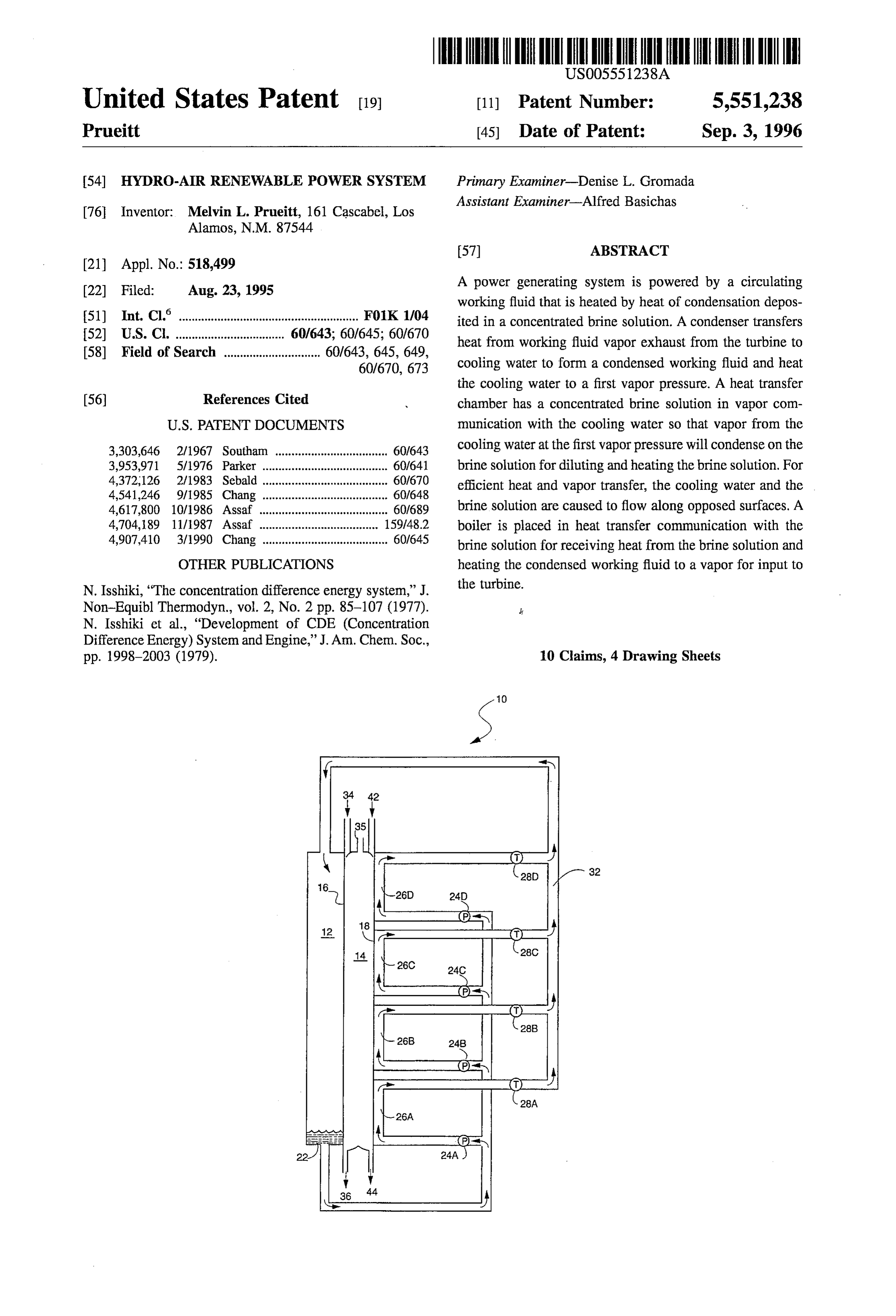
the concentrated brine solution. A boiler contacts the con transfer chamber 14 is evacuated, e.g., by vacuum pump, air densed working fluid with a second surface of the second ejector, or the like 35, to enhance vapor flow within the heat transfer partition so that the working fluid is heated to chamber. As water is heated in chamber 14, the vapor a vapor state for turning the turbine as the concentrated brine pressure of the water is increased and vapor is formed. The solution is heated and diluted from condensation of the 5 vapor condenses on a concentrated brine solution within vapor from the flowing water. chamber 14 with a concomitant heating of the brine. The heat in the brine is transferred to one or more boilers 26A-D
A brine concentrator is provided as a component part of to heat a working fluid to drive a power generator such as the power generating system. In accordance with one one or more turbines 28A-D, where the number of turbines embodiment, the brine concentrator includes an air flow heat is determined by the dilution change in the concentrated exchanger for admitting hot dry air at one end and for O brine.
exhausting cool humid air at another end. A warm water loop Accordingly, a working fluid delivers energy to turbines contacts the air flow heat exchanger for extracting heat from 28A-D and the energy-depleted working fluid is delivered to the air flow to heat a circulating water flow. A cool water exhaust return 32. As used herein, a working fluid may be loop contacts the air flow heat exchanger for adding energy waterlsteam, but is preferably a refrigerant, such as ammo to the air. A water spray in the air flow heat exchanger 15 nia or propane. Refrigerants produce high pressure vapor at intermediate the warm water loop and the cool water loop relatively low temperature so that a smaller turbine is acts as an energy exchange medium between the cool water required.
loop and the hot dry air. A brine concentrating unit receives The vapor in exhaust return 32 is delivered to condenser relatively dilute brine, wherein the relatively dilute brine is 12. Condenser 12 includes heat exchange partition 16 with heated by the warm water loop to evaporate water from the 20 a first surface for condensing the vapor. A second surface of brine solution to form a more concentrated brine solution heat exchange partition 16 also defines one surface of heat and the evaporated water is condensed by the cool water transfer chamber 14 and is cooled by flowing water from loop. water inlet 34. The water may be derived from concentrating In another embodiment of a brine concentrator, a plurality brine solution, as discussed below, or may be from an of brine outlets inputs a relatively dilute brine solution. A 25 independent water source. As water flows along the second surface of partition 16, vapor adjacent the first surface is plurality of flow plates receives the brine solution for flowing the relatively dilute brine solution along a plurality condensed, releasing its latent heat of vaporization, which is of parallel chambers. An ambient dry air flow contacts the transferred to partition 16 and to water on the second surface relatively dilute brine solution for evaporating water from to heat the water.
the solution to form a relatively concentrated brine solution. 30 Heat transfer chamber 14 is further defined by second heat In yet another embodiment of a brine concentrator, a transfer partition 18. A concentrated brine solution is pro plurality of spray heads dispenses a relatively dilute brine vided along a first surface of second heat transfer partition solution as a brine spray in a first direction. An ambient air 18 through brine inlet 42. The vapor pressure of the water on flow is input in a second direct opposite the first direction at the second surface of partition 16 is higher than that of the a velocity effective to slow the fall rate of the droplets and condensed brine solution on the first surface of second heat increase the time of contact between the droplets and the air 35 transfer partition 18. Accordingly, vapor from the water will whereby water is evaporated from the droplets for increased flow to and condense on the brine surface. As the vapor concentration of the brine in the droplets. A plurality of condenses, the latent heat of vaporization and the heat of troughs faces the spray heads for collecting the concentrated solution are released to heat the brine. The temperature of brine droplets. the brine will increase until an equilibrium vapor pressure is 40 reached. The temperature difference between the water and
BRIEF DESCRIPTION OF THE DRAWINGS the brine may be 20° C. or higher depending on the brine concentration.
The accompanying drawings, which are incorporated in Thus, in heat transfer chamber 14 water flows down one and form a part of the specification, illustrate the embodi surface and exits at outlet 36. Concentrated brine flows ments of the present invention and, together with the 45 down an opposing surface. As the water looses heat by description, serve to explain the principles of the invention. evaporation, heat is continuously supplied through partition In the drawings: 16. from the condenser, where the refrigerant vapor is FIG. 1 is a schematic diagram of a power generating condensing. This transfer method efficiently transfers large system according to one embodiment of the present inven quantities of heat. Hot brine on partition 18 delivers its heat tion.
to a refrigerant boiler through partition 18 until the hot,
FIG. 2 is a schematic diagram of a power generating dilute brine exits through outlet 44. system according to a second embodiment of the present One of the energy losses in most low-temperature power invention. systems is that the heat source loses some quality as heat is FIG. 3 is a schematic diagram of a brine concentrator as transferred. In the case of brine, the brine becomes diluted a component of the power generating system. as it absorbs water vapor and is able to support progressively 55 lower temperatures. The refrigerant and boiler effectively
FIG. 4 is a schematic diagram of a spray brine concen operate at the lowest temperature of the heat energy that is trator as a component of the power generating system. provided.
FIG. 5 is a schematic diagram of a brine concentrator In the prior art approach to minimize reduced heat quality, using warm/cool air flows. the brine is diluted only slightly, but this does not efficiently 60 use the brine and large brine storage is required. In accor
DETALED DESCRIPTION OF THE
INVENTION dance with the present invention, the brine is more effi ciently used by diluting the brine to a greater degree than
Referring first to FIG. 1, there is depicted a schematic prior art embodiments. A first embodiment is shown in FIG. diagram of a power generating system 10 according to one 1, where a plurality of parallel boiler loops are provided. embodiment of the present invention. Condenser 122 func 65 Four loops are shown herein for illustration only. tions to transfer heat from an exhaust working fluid vapor to Brine with the largest concentration enters through inlet water in heat transfer chamber 14. In one embodiment, heat 42 and is heated as described above. This heat is transferred
Page 8
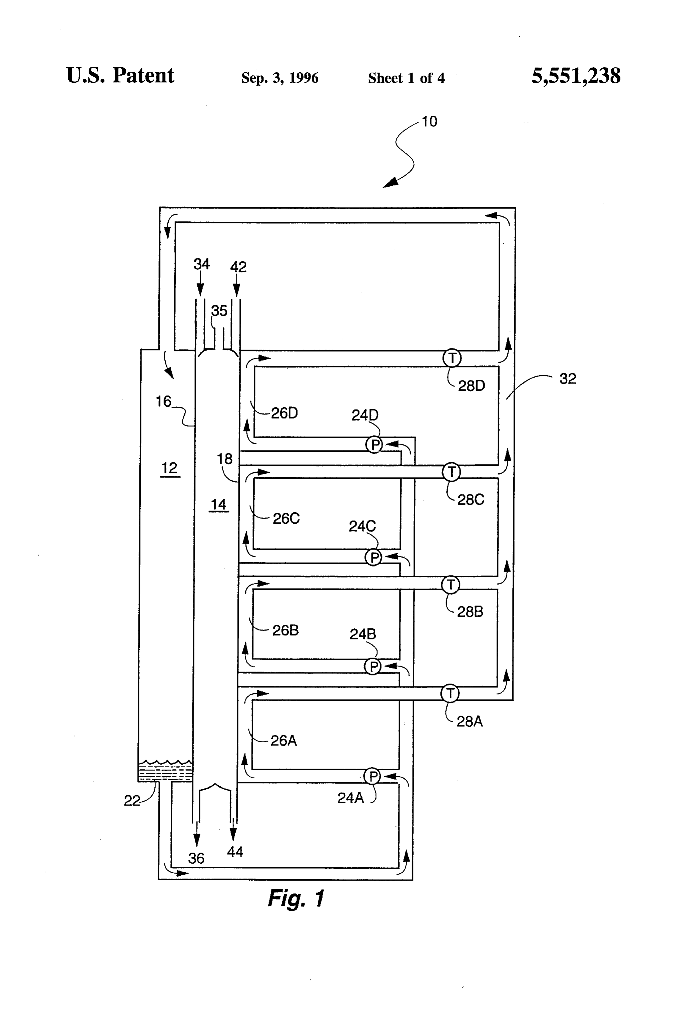
to refrigerant in boiler 26D at the highest temperature, which require a variety of auxiliary pumps and valves to circulate vaporizes and drives turbine 28D. The brine is slightly the water and brine flows. In addition, various heat exchang diluted and then flows to the surface adjacent to boiler 26C. ers may be provided to transfer the heat in exhaust water and Boiler 26C is then heated, but to a lower temperature, to dilute brine to inlet water and concentrated brine before the driver turbine 28C. Each succeeding boiler, boilers 26B and water and brine are returned to the heat exchanger units. The 26A operates at progressively lower temperature as the brine design of these auxiliary systems are not within the scope of is progressively diluted. All of the four boiler stages exhaust the present invention and are not discussed in detail herein. to return line 32 for condensation in condenser 12. Conden The systems shown in FIGS. 1 and 2 require a source of sate 22 is returned to the respective boiler stages by pumps concentrated brine, where the brine stores ambient energy as 24A-D. concentration energy. It is contemplated that such plants will Simulations show that a two stage system produces 25% O be built where the humidity is low and there is an availability more energy than a single stage system for the same amount of water, e.g., sea water. Humidity is generally lower during of brine. A three stage plant produces 35% more energy than the day so that the brine concentrator can run during the day a single stage and a four stage system produces 40% more. to supply concentrated brine to the power plant and to It will also be appreciated that the physical geometry of produce extra brine for night operations. For example, a tank condenser 12 and heat transfer chamber 14 can be adapted 15 20 meters high and 50 meters in radius could supply a 100 to a variety of forms. A simple plate geometry might be used, MW power plant for 24 hours.
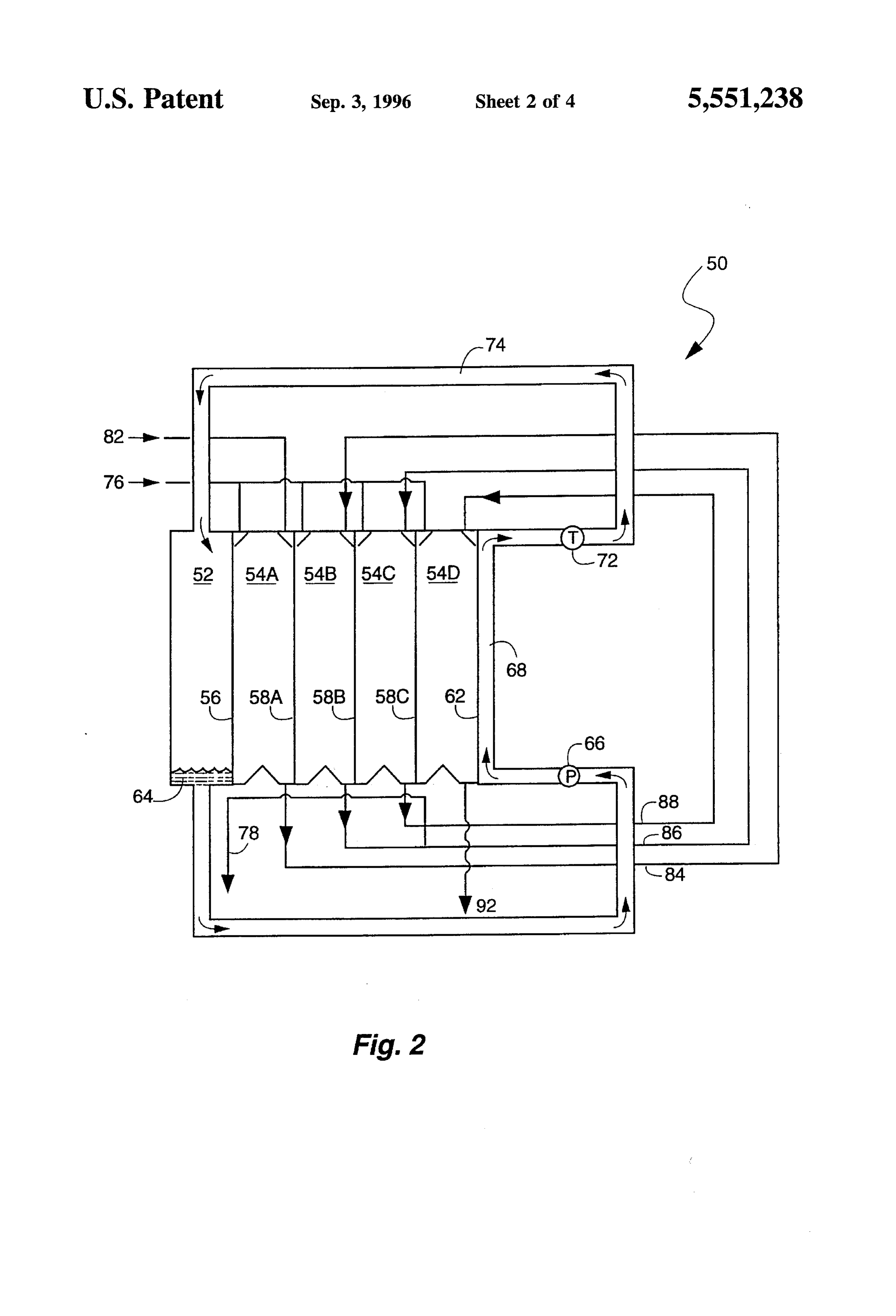
or a nested tube geometry, or other suitable ways of serially With sulfuric acid as the brine and propane as the refrig extracting heat from brine. erant, and with an ambient air temperature of 40°C. and a FIG. 2 shows in schematic form a power generating relative humidity of 15%, simulations show that a power system 50 for using only a single turbine and generator 72. 20 plant described above could operate at an efficiency of about In this embodiment, a plurality of heat transfer chamber 3.6%. That is, for every gram of water used by the plant, 58A-D is used. Exhaust vapor return 74 is provided to 87.4 joules of energy are produced. condenser 52 with first heat transfer partition 56. As Suitable brine concentrators are shown in FIGS. 3, 4, and described above, the latent heat of condensation is trans 5. In FIGS. 3 and 4, the brine flow is provided counter to a ferred as vapor condenses on a first surface of partition 56 25 hot, dry air flow. FIG. 3 depicts a concentrator 100 having and heats water introduced through water inlet 76 to a a plurality of brine flow walls 102A-F, where brine is second surface of partition 56 that forms one surface of heat introduced through dispensers 104A-F, respectively. Air transfer chamber 54A. Brine is input to heat transfer cham flow 106 is introduced to flow in a direction opposite to brine ber 54A through concentrated brine solution inlet 82 to flow so that when the air is the hottest and driest, the brine is the along a first surface of second heat transfer partition 58A. most concentrated with the lowest vapor pressure but can The concentrated brine solution is heated as described for 30 still evaporate water to the hot, dry air. Brine is collected in
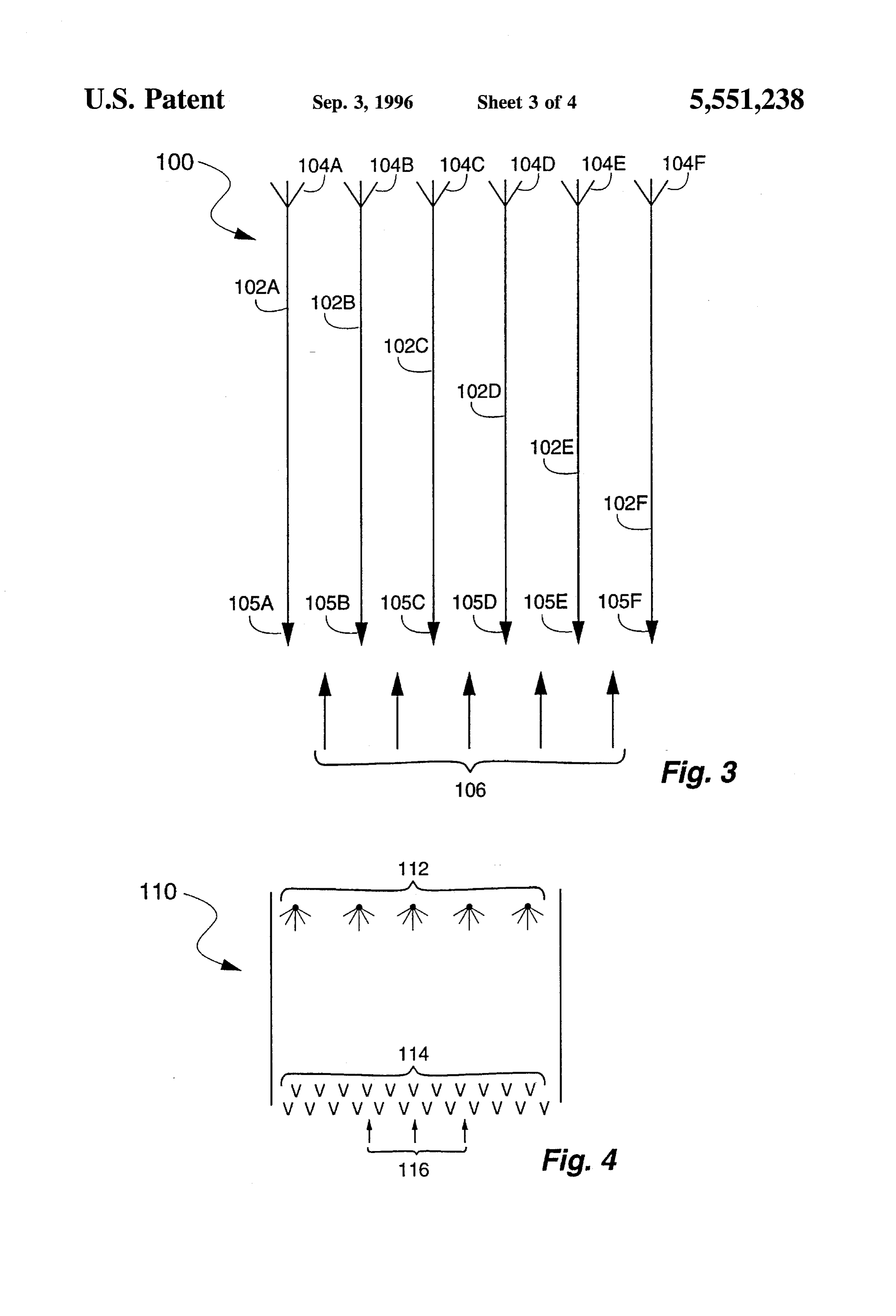
F.G. 1. troughs 105A-F. Channel walls 102A-F are preferably In the embodiment shown in FIG. 2, a plurality of heat designed to slow the movement of the brine to increase the transfer chambers 58A-D is provided for heating the brine time of contact between the brine and the air. Exemplary in stages. Heated brine from chamber 58A exits through loop walls are slotted walls of thin metal or plastic or of a fabric 84 for input to heat transfer chamber 54B. Likewise, heated 35 or screen with surface features that reduce the brine flow brine from chamber 58B exits through loop 86 for input to rate. Rather than a counter-flow of air and brine, a cross-flow heat transfer chamber 54C; heated brine from chamber 58C of air could be used with the air flowing in the channels exits through loop 88 for input to heat transfer chamber 54D. defined by brine flow walls 102A-F perpendicular to the Water is input through water inlet 76 and is flowed along a flow of brine along the surfaces, as discussed above. corresponding second surface of a heat transfer partition Another embodiment is shown in FIG. 4, where concen 54B-D. The water is provided to the heat transfer partitions trator 110 provides brine sprayers 112 to dispense the brine in parallel and is used in each heat transfer chamber and is as a spray. With relatively uniform droplet sizes, airflow 116 discharged through outlet 78. can be adjusted so that the droplets are affected by the air Thus, brine is heated in heat transfer chamber 54A and is flow and fall at a slow rate to maximize exposure to the hot transferred to flow along a first surface of heat transfer 45 dry air. Water in the droplets is evaporated by the dry air so partition 58B in heat transfer chamber 54B. Water is heated the brine in the droplets becomes more concentrated. Over along the second surface of heat transfer partition 58A and lapping rows of catch troughs 114 collect the concentrated the vapor condenses on the brine to heat the brine for heat brine. In one embodiment, the walls of each catch trough 114 transfer across heat transfer partition 58B. The process are V-shaped, with the V having a small internal angle, i.e., continues serially across heat transfer partitions 58B and 50 a steep external angle, to reduce the production of secondary 58C. This process produces a high temperature brine on a droplets.
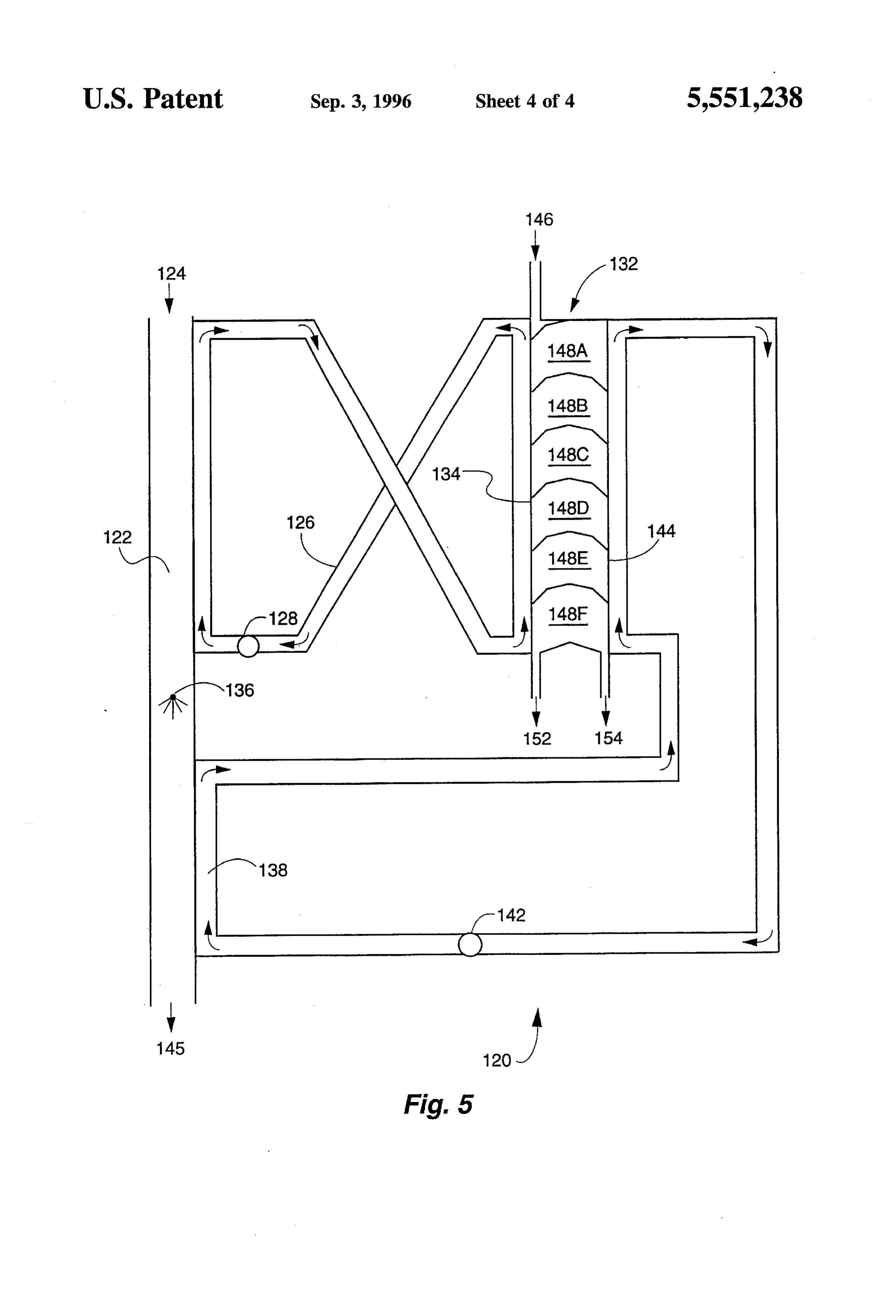
first surface of heat transfer partition 62 for heat transfer to One of the problems with the brine concentrators shown a refrigerant in boiler 68. The heated, dilute brine exits in FIGS. 3 and 4 is that the brine must be deaerated before through outlet 92. For example, if the brine in chamber 58A entering a heat transfer chamber of the power unit shown in is heated to a temperature difference of 20° C. above the 55 FIGS. 1 and 2, particularly where the heat transfer i 1) water film temperature on heat transfer partition 56, the chamber is evacuated. This difficulty is avoided by brine brine in chamber 54B is heated to a temperature difference concentrator system 120 shown in FIG. 5. Water in loop 126 of 15° C., the brine in chamber 54C is heated to a tempera is first heated by hot air 124 in a first section of heat ture difference of 10° C., and 5° C. in chamber 54D, then the exchanger 122. Water in loop 126 flows counter to hot air total temperature difference between condenser 52 and 124 for maximum water heating. Pump 128 circulates the boiler 68 is then 50° C. 60 heated water to brine concentrator unit 132. A dilute brine is Condensate 64 is circulated by pump 66 along a second introduced through inlet 146 to flow along a first surface 134 surface of heat transfer partition 62 to provide a relatively of concentrator unit 132 that is heated by water in heater high pressure vapor to drive turbine 72. Turbine 72 operates loop 126. As the brine is heated, water evaporates from the at a relatively high temperature and concomitant pressure for brine and condenses on a second surface 144 of concentrator a high power output. 65 unit 132.
It will be appreciated by those of ordinary skill in the art The second surface of concentrator unit 132 is cooled by that the energy generating systems shown in FIGS. 1 and 2 water circulating in loop 138 by pump 142. Heat exchanger
Page 9
122 also provides for cooling hot dry air 124 after the air 4. A power generating system according to claim 1, traverses the first section of heat exchanger 122. Water wherein said heat transfer chamber is a plurality of heat sprayer 136 provides a water mist within a second section of transfer chambers connected in series whereby said brine heat exchanger 122. The water mist contacts a surface that solution is increased in temperature as said brine solution is heated by the cooling water in loop 138, whereby the traverses each one of said plurality of heat transfer cham water mist evaporates and cools the cooling water for return bers.
to concentrator unit 132. The air is exhausted through outlet 5. A power generating system according to claim 1, 145. further including a brine concentrator using hot dry air as an Brine concentrator unit 132 is divided into a plurality, energy source for storing energy as a concentrated brine solution.
illustrated by chambers 148A-F in one exemplary embodi 10 6. A power generating system having a turbine powered ment. Both the heated water flow in loop 126 and the cooling by a circulating working fluid, said system comprising: water flow in loop 138 are opposite the brine flow in a condenser chamber having a first heat transfer partition concentrator unit 132. Chambers 148A-F are provided with for condensing exhaust vapor of said working fluid baffles so that different vapor pressures may be maintained from said turbine on a first surface wherein a first latent in each chamber. Vapor pressure is highest in chamber 148A 15 heat of condensation heats said first heat transfer par and lowest in chamber 148F Concentrated brine drains along the heated surface 134 of concentration unit 132 and tition to form condensed working fluid from said vapor, water condensate collects and drains along the cooled sur a heat transfer chamber formed by a second surface of face 144. Concentrated brine is returned through outlet 152 said first heat transfer partition and a first surface of a to a storage tank or to a power generating system where the second heat transfer partition, wherein said first surface brine is again diluted as power is extracted. Pure water is 20 of said second heat transfer partition is separated from outlet through outlet 154 and may be used as makeup and in vapor communication with said second surface process water for the power generating system. Since a of said first heat transfer partition; closed system is provided for the concentrated brine and a water inlet for flowing water along said second surface output water, no dearation is needed for use of the fluids in of said first heat transfer partition, wherein said flowing the power generation systems shown in FIGS. 1 and 2. 25 water is heated to have a first vapor pressure by transfer The foregoing description of the preferred embodiments of said first latent heat of condensation through said of the invention have been presented for purposes of illus first heat transfer partition; tration and description. It is not intended to be exhaustive or a concentrated brine inlet for flowing concentrated brine to limit the invention to the precise form disclosed, and along said first surface of said second heat transfer obviously many modifications and variations are possible in 30 partition, wherein said concentrated brine has a second light of the above teaching. The embodiments were chosen vapor pressure less than said first vapor pressure of said and described in order to best explain the principles of the flowing water so that vapor from said flowing water invention and its practical application to thereby enable others skilled in the art to best utilize the invention in various condenses on said flowing concentrated brine to release embodiments and with various modifications as are suited to a second heat of condensation to heat said concentrated the particular use contemplated. It is intended that the scope 35 brine solution and cool said flowing water, of the invention be defined by the claims appended hereto. a boiler for contacting said condensed working fluid with What is claimed is: a second surface of said second heat transfer partition 1. A power generating system having a turbine powered so that said working fluid is heated to a vapor state for by a circulating working fluid, said system comprising: 40 turning said turbine by said concentrated brine solution a condenser for transferring heat from working fluid vapor as said concentrated brine solution is heated and diluted exhaust from said turbine to cooling water for condens from condensation of said vapor from said flowing ing said working fluid vapor and heating said cooling Water.
water to a first vapor pressure; 7. A power generating system according to claim 6, a heat transfer chamber having a concentrated brine 45 wherein said boiler is a plurality of boilers connected in solution in vapor communication with said cooling series along said heat transfer chamber wherein said brine water so that vapor from said cooling water at said first solution serially traverses each one of said plurality of boilers.
vapor pressure will condense on said brine solution for 8. A power generating system according to claim 7, where diluting and heating said brine solution; and said brine is diluted by a predetermined amount as said brine a boiler in heat transfer communication with said brine 50 serially traverses each one of said plurality of boilers. solution for receiving heat from said brine solution and 9. A power generating system according to claim 6, heating said condensed working fluid to a vapor for wherein said heat transfer chamber is a plurality of heat input to said turbine. transfer chambers connected in series whereby said brine 2. A power generating system according to claim 1, solution is increased in temperature as said brine solution wherein said boiler is a plurality of boilers connected in 55 traverses each one of said plurality of heat transfer cham series along said heat transfer chamber wherein said brine bers.
solution serially traverses each one of said plurality of 10. A power generating system according to claim 6, boilers. further including a brine concentrator using hot dry air as an 3. A power generating system according to claim 2, energy source for storing energy as a concentrated brine wherein said brine is diluted by a predetermined amount as 60 solution.
said brine serially traverses each one of said plurality of boilers.
Provenance
- Collection
- Cited prior art
- Original PDF
- patentimages.storage.googleapis.com →
- Filed
- 1995-08-23
- Pages
- 9
- Method
- pdftotext (the PDF's own text layer) + pdftoppm 300dpi page scans
- Source
- Google Patents bibliographic record
- Granted
- 1996-09-03
- Inventors
- Melvin L. Prueitt
- Transcribed from
- patentimages.storage.googleapis.com →