patent · US3953971
Power generation arrangement
4 May 1976
Page 1 — bibliographic record
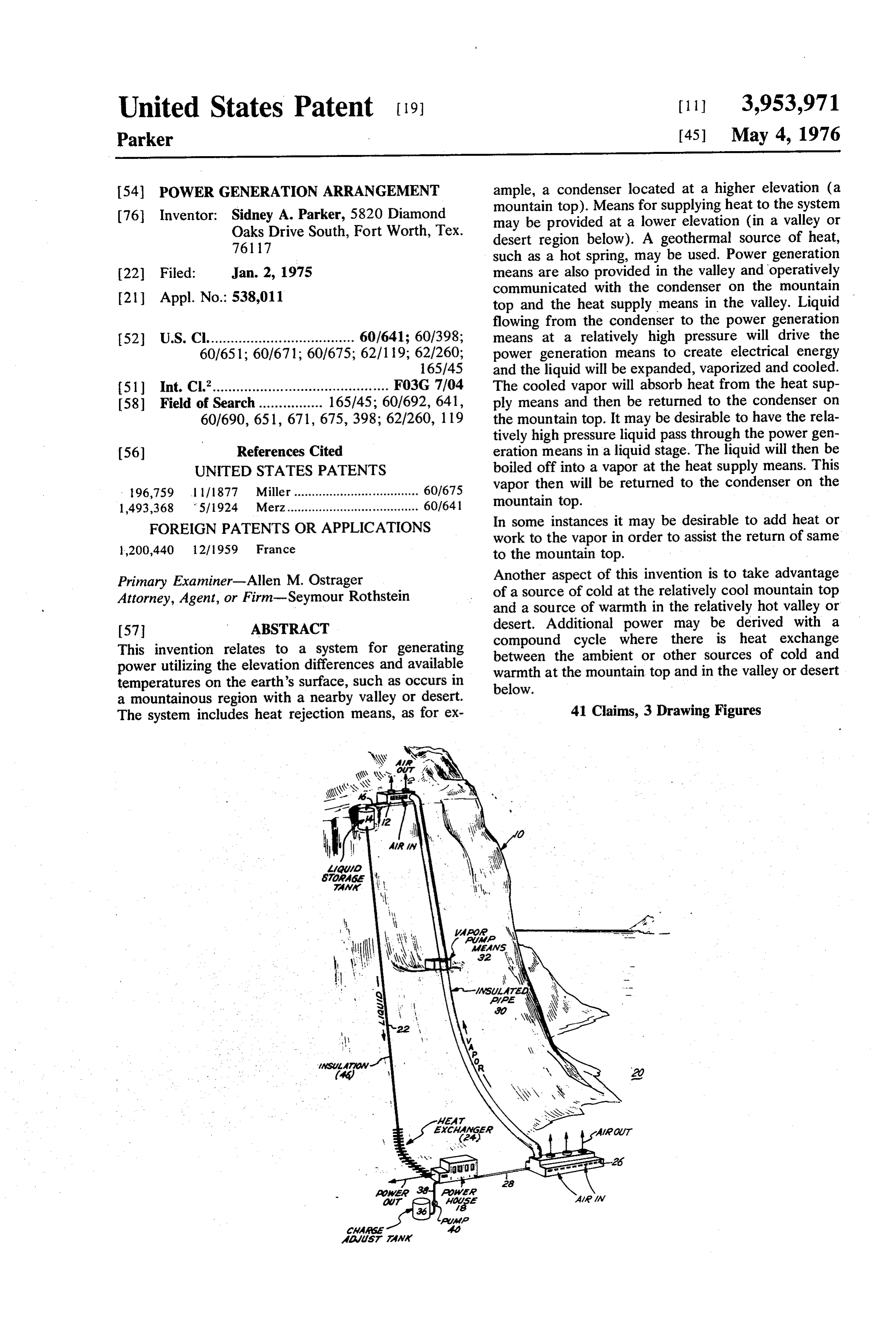
United States Patent (19) 11, 3,953,971 Parker (45) May 4, 1976 54 POWER GENERATION ARRANGEMENT ample, a condenser located at a higher elevation (a 76 Inventor: Sidney A. Parker, 5820 Diamond mountain top). Means for supplying heat to the system Oaks Drive South, Fort Worth, Tex. may be provided at a lower elevation (in a valley or 76117 desert region below). A geothermal source of heat, such as a hot spring, may be used. Power generation (22 Filed: Jan. 2, 1975 means are also provided in the valley and operatively communicated with the condenser on the mountain 21 Appl. No.: 538,011 top and the heat supply means in the valley. Liquid flowing from the condenser to the power generation 52 U.S. Cl..................................... 60/641; 60/398; means at a relatively high pressure will drive the 60/651; 60/671; 60/675; 62/1 19; 62/260; power generation means to create electrical energy 165/45 and the liquid will be expanded, vaporized and cooled.
51) Int. Cl............................................. F03G 7/04 The cooled vapor will absorb heat from the heat sup 58) Field of Search ................ 165/45; 60/692, 641, ply means and then be returned to the condenser on 60/690, 651, 671, 675, 398; 62/260, 119 the mountain top. It may be desirable to have the rela tively high pressure liquid pass through the power gen (56) References Cited eration means in a liquid stage. The liquid will then be UNITED STATES PATENTS boiled off into a vapor at the heat supply means. This 196,759 1 1/1877 Miller ................................... 60/675 vapor then will be returned to the condenser on the 1,493,368 5/1924 Merz..................................... 60/641 mountain top.
FOREIGN PATENTS ORAPPLICATIONS In some instances it may be desirable to add heat or work to the vapor in order to assist the return of same 1,200,440 12/1959 France to the mountain top.
Primary Examiner-Allen M. Ostrager Another aspect of this invention is to take advantage Attorney, Agent, or Firm-Seymour Rothstein of a source of cold at the relatively cool mountain top and a source of warmth in the relatively hot valley or 57 ABSTRACT desert. Additional power may be derived with a This invention relates to a system for generating compound cycle where there is heat exchange between the ambient or other sources of cold and power utilizing the elevation differences and available warmth at the mountain top and in the valley or desert temperatures on the earth's surface, such as occurs in below.
a mountainous region with a nearby valley or desert.
The system includes heat rejection means, as for ex 41 Claims, 3 Drawing Figures
aws7 away
Page 2
Drawing sheet — no readable text.
Page 3
Drawing sheet — no readable text.
Page 4
FIG. 3 shows yet another modification of FIG. 1
POWER GENERATION ARRANGEMENT where a compound cycle has been added for more efficient use of the available energy.
BACKGROUND AND SUMMARY OF THE
INVENTION DETAILED DESCRIPTION OF THE PREFERRED
EMBODIMENT
This invention relates to a system for generating Referring now to FIG. 1, there is illustrated a power power utilizing the elevation differences and available generation system embodying principles of the present temperatures on the earth's surface. invention. The present system is adapted to be utilized For some time, concern has been expressed regard 10 on the earth's surface ing the availability of natural resources to provide the tively large elevation indifferences an area where there are rela increasing power demands of the inhabitants of the mate points on the earth's surface,between the proxi earth. The recent oil crises brought into focus the in mountain top and the valley below. It is known, fora as for example, creasing demands for power in our country and else example, from the Ashrae Guide 1963, page 39, that where. In considering the various means for generating 15 the definition of a standard atmosphere is T - To - power, it occurred to me that better use could be made 0.003566Z, where T is temperature in degress Fahren of the earth's topography and that an efficient power heit at an elevation Z. To is temperature in degress generating system could be provided that utilized the Fahrenheit at sea level and Z is elevation in feet. The elevation differences on the earth's surface and the practical limit for this relationship is 35,332 feet. Relat available temperatures on the earth's surface. A num 20 ing this equation to temperatures at different eleva ber of regions in our country and elsewhere around the tions, the relationship is expressed as T. T - world have relatively high mountains which are rela 0.003566 (Z - Z.) where T is a temperature in de tively cool at the top and relatively low valleys nearby grees Fahrenheit at a lower elevation, as for example, which are relatively warm. These regions have tremen at sea level; and Z is the lower elevation in feet. T is dous potential energy that can be tapped to provide 25 the temperature at the upper elevation in degrees Fahr electrical power in large amounts. enheit and Z is the elevation at the upper level in feet. An object of the present invention is to provide novel One area with large available heat and elevation means for generating power utilizing the elevational differences would be Peru and Chile in South America differences and available temperatures on the earth's 30 where the Andes Mountains are on the order of 20,000 surface. feet high, thus providing a substantial elevation differ Another object of the present invention is to provide ence. Here, there are relatively cool temperatures in an improved system for generating power that includes the mountains and relatively warm temperatures in the heat rejection means disposed at a relatively cool high valleys or Pacific Ocean below. Many areas within the place on the earth's surface, a heat supply means dis 35 United States would similarly be suitable, as for exam posed at a relatively warm lower level on the earth's level ple, the Death Valley region. Death Valley is below sea surface, power generation means at the lower level, a orderand of reaches temperatures in the daytime on the 135°F. Not far away is Telescope Peak, which relatively small diameter conduit communicating the is 11,045 feet high. The elevation difference between heat rejection means with the power generation means, the and a relatively large diameter insulated conduit com 40 feet.valley and the mountain top-is in excess of 1 1,300. Regions such as this provide the necessary tem municating the heat rejection means, whereby liquid peratures and elevational differences required for effi flowing through the small diameter conduit will actuate cient operation of my improved power generation sys the power generation means and either be emitted as a te.
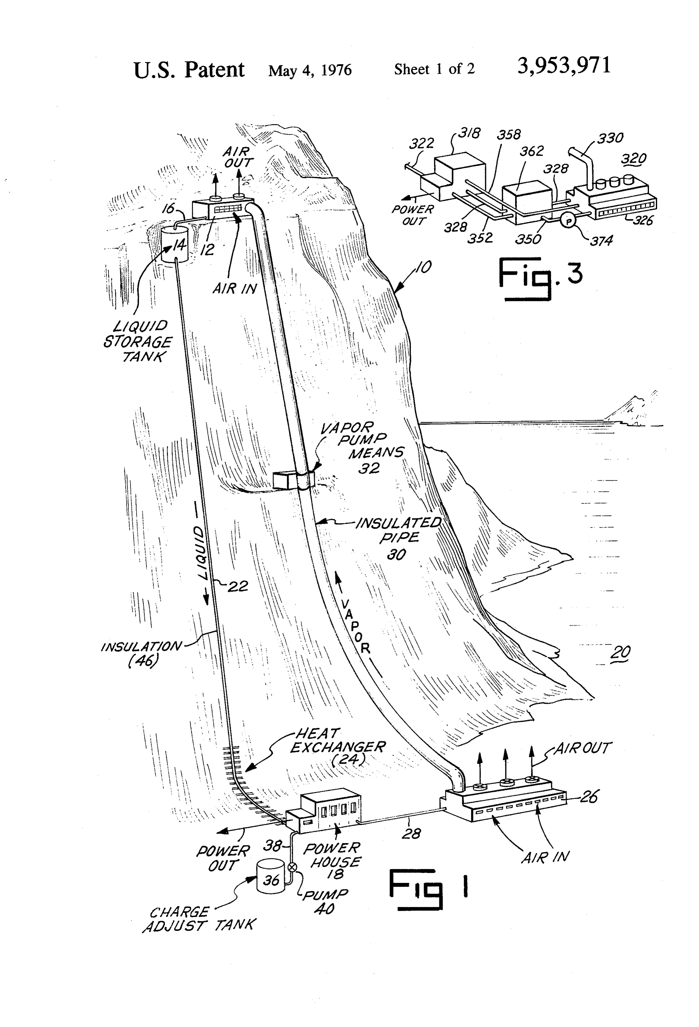
liquid or be flashed into vapor, with heat being added at Referring to FIG. 1, the mountain 10 is provided at a the heat supply means to assist in returning the vapor to 45 location proximate the top thereof with a heat ex the heat rejection means.
Yet another object of the invention is to provide an cooled type,condenser changer or
12, which is preferably of the air take advantage of the natural air improved system for generating power that includes a currents available. It is within the scope of this inven compound cycle. The compound cycle has a heat ex tion to utilize a water-cooled condenser.
changer either before or after the power generation 50 age tank 14 is provided on the mountainAtop liquid stor in close means, depending on the system, and a second heat proximity to the condenser 12 and is communicated to exchanger independent of the heat supply means, with the condenser 12 by a relatively short and small diame a second power generation means situated between the ter conduit 16.
two heat exchangers, and a relatively large vapor line A power house 18 is provided in the valley 20. Pref connecting the two heat exchangers. 55 erably, there is a maximum elevation difference be Other objects and advantages of the present inven tween the power house 18 and the condenser 12. A tion will be made more apparent hereinafter. conduit 22 of relatively small diameter connects the liquid storage tank 14 with the power house 18. Heat
BRIEF DESCRIPTION OF THE DRAWINGS exchanger 24 may be provided in the conduit 22 adja There is illustrated in the attached drawing presently 60 cent or in relatively close proximity to the power house preferred embodiments of the present invention, 18 in order to supply heat to the liquid entering the wherein: power house, if desired. Liquid line 22 may or may not FIG. 1 is a perspective view of one form of the be insulated.
present system illustrating the essential components 65 Liquid entering the power house 18 will drive power thereof and the relationship between the components generating means, for example, a turbine, and the liq on the earth's surface; uid will be emitted as a liquid or be cooled and vapor FIG. 2 illustrates a modification of the system of FIG. ized. Such vapor or liquid will flow through conduit 28 1; and to heat exchanger 26, provided in the valley 20, at as
Page 5
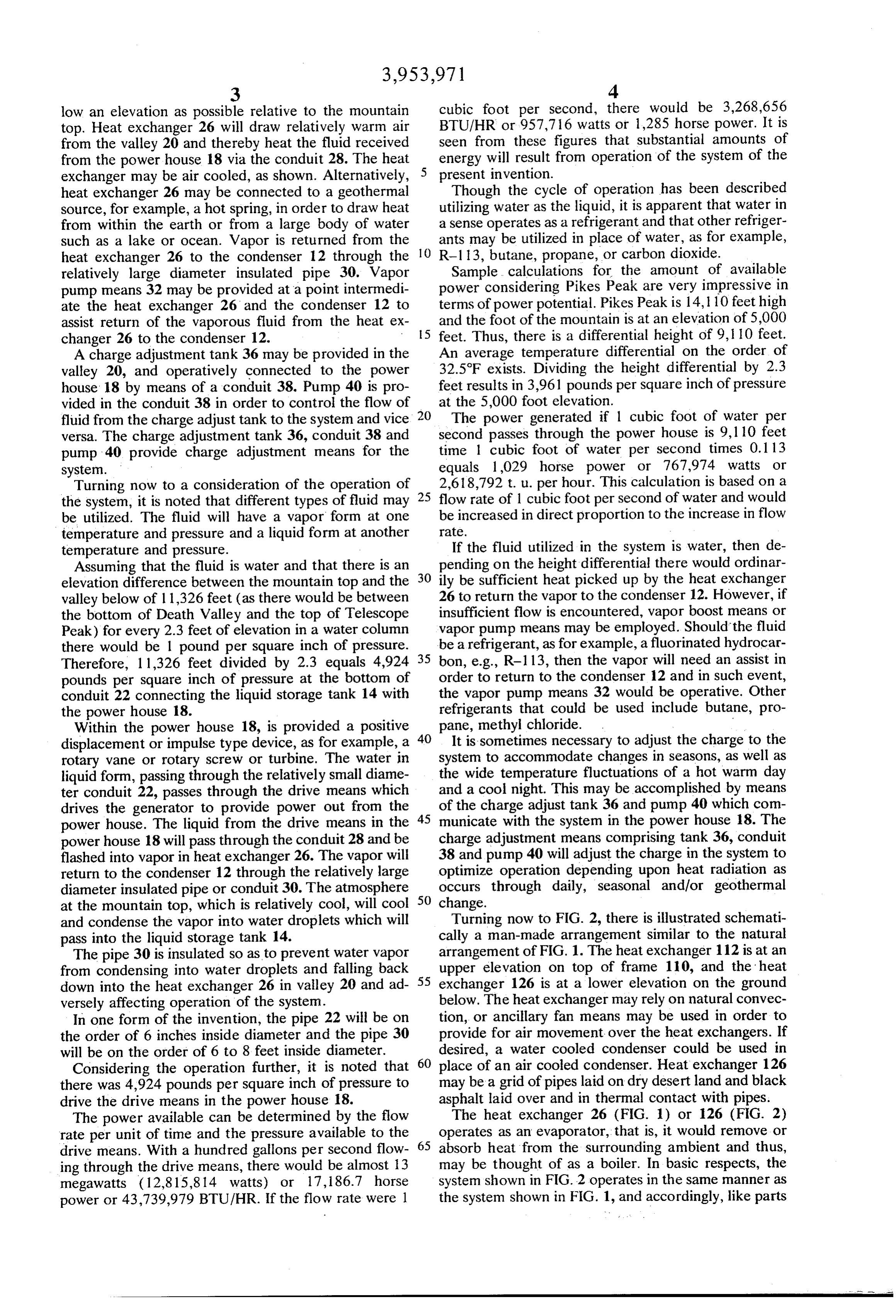
low an elevation as possible relative to the mountain cubic foot per second, there would be 3,268,656 top. Heat exchanger 26 will draw relatively warm air BTU/HR or 957,716 watts or 1,285 horse power. It is from the valley 20 and thereby heat the fluid received seen from these figures that substantial amounts of from the power house 18 via the conduit 28. The heat energy will result from operation of the system of the exchanger may be air cooled, as shown. Alternatively, 5 present invention. - heat exchanger 26 may be connected to a geothermal Though the cycle of operation has been described Source, for example, a hot spring, in order to draw heat utilizing water as the liquid, it is apparent that water in from within the earth or from a large body of water a sense operates as a refrigerant and that other refriger such as a lake or ocean. Vapor is returned from the 10 ants may be utilized in place of water, as for example, heat exchanger 26 to the condenser 12 through the R-1 13, butane, propane, or carbon dioxide. relatively large diameter insulated pipe 30, Vapor Sample calculations for the amount of available pump means 32 may be provided at a point intermedi power considering Pikes Peak are very impressive in ate the heat exchanger 26 and the condenser 12 to terms of power potential. Pikes Peak is 14, 10 feet high assist return of the vaporous fluid from the heat ex 5 and the foot of the mountain is at an elevation of 5,000 changer 26 to the condenser 12. feet. Thus, there is a differential height of 9, 10 feet. A charge adjustment tank 36 may be provided in the An average temperature differential on the order of valley 20, and operatively connected to the power 32.5°F exists. Dividing the height differential by 2.3 house 18 by means of a conduit 38. Pump 40 is pro feet results in 3,961 pounds per square inch of pressure vided in the conduit 38 in order to control the flow of at the 5,000 foot elevation. fluid from the charge adjust tank to the system and vice 20 The power generated if 1 cubic foot of water per versa. The charge adjustment tank 36, conduit 38 and second passes through the power house is 9,110 feet pump 40 provide charge adjustment means for the time 1 cubic foot of water per second times 0.1 13 system. equals 1,029 horse power or 767,974 watts or Turning now to a consideration of the operation of 25 2,618,792 t. u. per hour. This calculation is based on a the system, it is noted that different types of fluid may flow rate of 1 cubic foot per second of water and would be utilized. The fluid will have a vapor form at one be increased in direct proportion to the increase in flow temperature and pressure and a liquid form at another rate.
temperature and pressure. If the fluid utilized in the system is water, then de Assuming that the fluid is water and that there is an 30 pending on the height differential there would ordinar elevation difference between the mountain top and the ily be sufficient heat picked up by the heat exchanger valley below of 11,326 feet (as there would be between 26 to return the vapor to the condenser 12. However, if the bottom of Death Valley and the top of Telescope insufficient flow is encountered, vapor boost means or Peak) for every 2.3 feet of elevation in a water column vapor pump means may be employed. Should the fluid there would be 1 pound per square inch of pressure. be a refrigerant, as for example, a fluorinated hydrocar Therefore, 1 1,326 feet divided by 2.3 equals 4,924 35 bon, e.g., R-113, then the vapor will need an assist in pounds per square inch of pressure at the bottom of order to return to the condenser 12 and in such event, conduit 22 connecting the liquid storage tank 14 with the vapor pump means 32 would be operative. Other the power house 18. refrigerants that could be used include butane, pro Within the power house 18, is provided a positive 40 pane, methyl chloride.
displacement or impulse type device, as for example, a It is sometimes necessary to adjust the charge to the rotary vane or rotary screw or turbine. The water in system to accommodate changes in seasons, as well as liquid form, passing through the relatively small diame the wide temperature fluctuations of a hot warm day ter conduit 22, passes through the drive means which and a cool night. This may be accomplished by means drives the generator to provide power out from the 45 of the charge adjust tank 36 and pump 40 which com power house. The liquid from the drive means in the municate with the system in the power house 18. The power house 18 will pass through the conduit 28 and be charge adjustment means comprising tank 36, conduit flashed into vapor in heat exchanger 26. The vapor will 38 and pump 40 will adjust the charge in the system to return to the condenser 12 through the relatively large optimize operation depending upon heat radiation as diameter insulated pipe or conduit 30. The atmosphere 50 occurs through daily, seasonal and/or geothermal at the mountain top, which is relatively cool, will cool change.
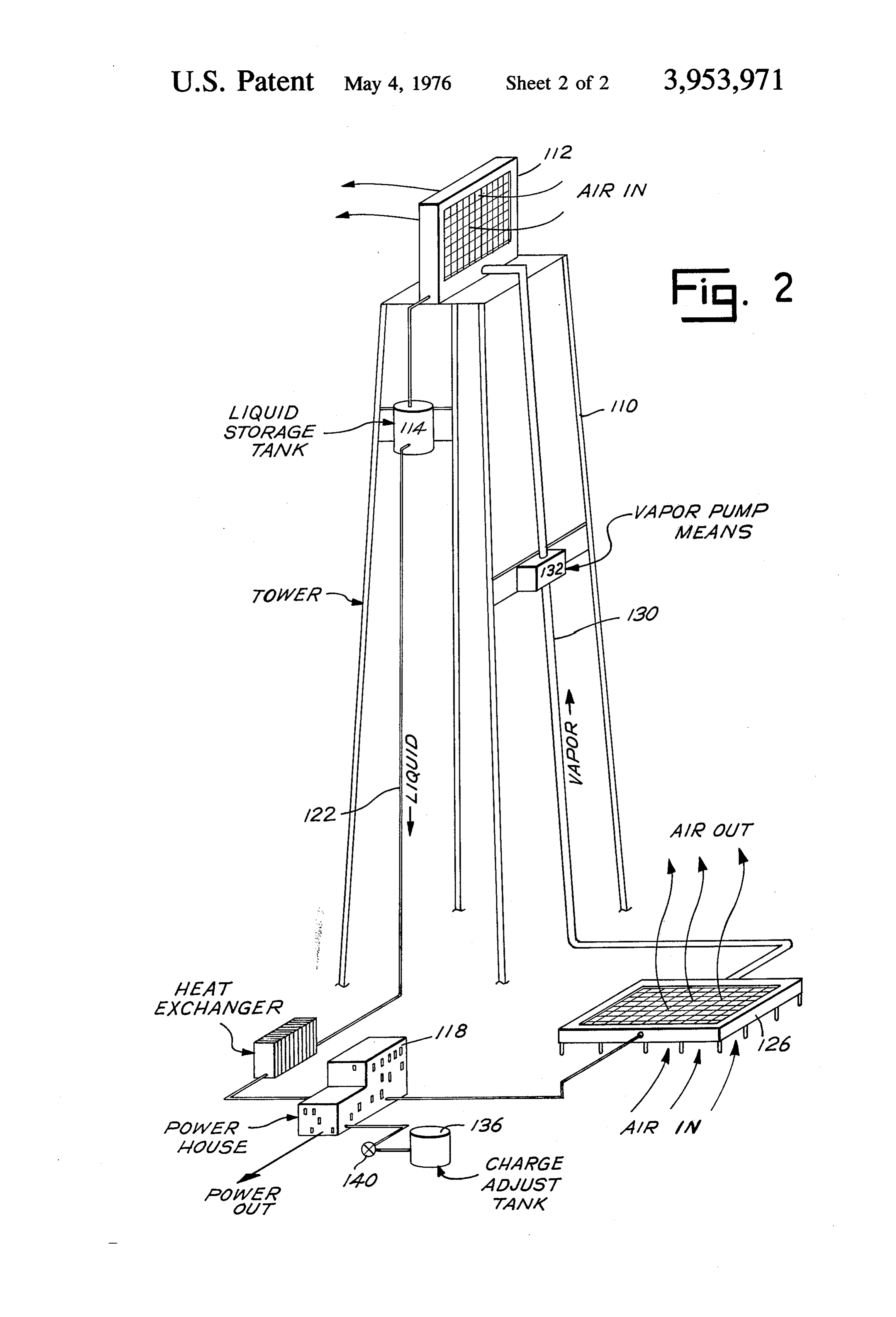
and condense the vapor into water droplets which will Turning now to FIG. 2, there is illustrated schemati pass into the liquid storage tank 14. cally a man-made arrangement similar to the natural The pipe 30 is insulated so as to prevent water vapor arrangement of FIG. 1. The heat exchanger 112 is at an from condensing into water droplets and falling back 55 upper elevation on top of frame 110, and the heat down into the heat exchanger 26 in valley 20 and ad exchanger 126 is at a lower elevation on the ground versely affecting operation of the system. below. The heat exchanger may rely on natural convec In one form of the invention, the pipe 22 will be on tion, or ancillary fan means may be used in order to the order of 6 inches inside diameter and the pipe 30 provide for air movement over the heat exchangers. If will be on the order of 6 to 8 feet inside diameter. desired, a water cooled condenser could be used in Considering the operation further, it is noted that 60 place of an air cooled condenser. Heat exchanger 126 there was 4,924 pounds per square inch of pressure to may be a grid of pipes laid on dry desert land and black drive the drive means in the power house 18. asphalt laid over and in thermal contact with pipes. The power available can be determined by the flow The heat exchanger 26 (FIG. 1) or 126 (FIG. 2) rate per unit of time and the pressure available to the 65 operates as an evaporator, that is, it would remove or drive means. With a hundred gallons per second flow absorb heat from the surrounding ambient and thus, ing through the drive means, there would be almost 13 may be thought of as a boiler. In basic respects, the megawatts (12,815,814 watts) or 17, 186.7 horse system shown in FIG. 2 operates in the same manner as power or 43,739,979 BTU/HR. If the flow rate were 1 the system shown in FIG. 1, and accordingly, like parts
Page 6
in FIG. 2 have been designated by the same numerals as 3. A system as in claim 1 including vapor pump in FIG. 1, plus the prefix 1. means in the relatively large diameter conduit means. Referring now to FIG. 3, a compound cycle can be 4. A system as in claim 1 wherein the relatively small added to either FIG. 1 or FIG. 2. FIG. 3 illustrates a diameter conduit means is thermally insulated. refinement of either FIG. 1 or FIG. 2 where additional 5 5. A system as in claim 1 including a heat exchanger energy can be generated by taking advantage of the in association with the small diameter conduit means for adding heat to the liquid in said small diameter temperature difference of the relatively cold liquid in conduit pipe 328 and the relatively warm valley 320. Pipes 322 means.
and 328 are insulated by suitable insulation to maintain O means6. A system as in claim 1 including charge adjust maximum energy potential. Heat exchanger 362 is in for adjusting the quantity of fluid in the system heat exchange relationship to the liquid within pipe for optimum operation depending upon heat radiation 328. Condensed liquid in pipe 350 is pumped by feed as occurs through daily, seasonal and/or geothermal pump 374 to the heat exchanger (not shown) in build changes. 7. A system as in claim 2 including vapor pump boost ing 326 and is expanded into relatively high pressure gas. It is then sent to power house 318 through pipe 358 15 means in the relatively large diameter conduit means. 8. A system as in claim 2 wherein the relatively small where energy is extracted from the relatively high pres sure gas, wherein the gas temperature is somewhat diameter conduit means is thermally insulated. reduced. The somewhat rarefied (expanded) gas is sent disposed 9. A system as in claim 2 wherein a heat exchanger is through pipe 352 and is further cooled and condensed 20 CaS. in the relatively small diameter conduit in heat exchanger 362. The condensed liquid exits heat 10. A system as in claim 2 including charge adjust exchanger 362 through pipe 350 and again the liquid is elevated in pressure by the feed pump 374 in pipe 350 ment means.
where the cycle starts over. 11. A system as in claim 3 wherein the relatively There has been provided by the present invention an 25 small diameter conduit means is thermally insulated. 12. A system as in claim 3 including a heat exchanger improved system for generating power utilizing the elevation differences and available temperatures on the in 13. the relatively small diameter conduit means. . ." A system as in claim 3 including charge adjust earth's surface. As evidenced from the calculations presented above, tremendous energy potential is avail ment 14. A means.
system as in claim 4 including a heat exchanger able utilizing applicant's system, with relatively little power input required and hence, little use of fossil in 15. the relatively small diameter conduit means. fuels. It is seen that the heat exchanger at the lower ment Ameans. system as in claim 4 including a charge adjust level in the applicant's system effectively utilizes the 16. A system as in claim 7 wherein
the relatively available heat from the valley or the heat from a geo thermal source. It is contemplated that solar heat could 35 small diameter conduit means is thermally insulated. be used in combination with the heat from the valley or in 17. the
A system as in claim 7 including a heat exchanger relatively small diameter conduit means.
lower level.
The potential of the applicant's power generation 18. A system as in claim 7 including charge adjust arrangement is very broad in terms of energy output tank 19.means.
A system as in claim 1 including compound versus fossil fuel (or like fuel) input. Among regions in 40 power generation means comprising secondary power the United States having desirable elevation and tem generation means and a secondary heat source at the perature differentials are Mt. Shasta, Mt. McKinley, lower elevation, wherein power is derived from the and Mt. Rainier.
While there has been disclosed presently preferred temperature difference between the relatively low tem perature fluid leaving the primary power generation embodiments of the invention, it will be understood 45 drive that the invention is not limited thereto since it may be leavingmeans said and the relatively warm temperature fluid heat source at the lower elevation.
otherwise embodied within the scope of the following 20. A system as in claim 2 including compound claims. power generation means comprising secondary power I claim:
1. A system for generating power utilizing the eleva 50 generation means and a secondary heat source in the tion difference between a higher elevation and a lower lower elevation, where power is derived from the tem elevation and available temperatures of the earth's perature ature difference between the relatively low temper fluid leaving the primary power generation drive surface comprising heat rejection means at a higher elevation, heat supply means at a lower elevation, means and the relatively warm temperature fluid leav power generation means at substantially the same level 55 ing21.saidAheat source at the lower elevation. system as in claim 3 including compound as the heat supply means between the heat rejection power generation means and the heat supply means, relatively small di generation means means comprising secondary power and a secondary heat source at the ameter conduit means communicating the heat rejec tion means and the power generation means and the lower elevation, wherein power is derived from the temperature difference between the relatively low tem heat supply means respectively, and relatively large 60 perature fluid leaving the primary power generation diameter insulated conduit means communicating the drive means and the relatively warm temperature fluid heat supply means with the heat rejection means, leaving said heat source at the lower elevation. whereby fluid flowing through the relatively small di ameter conduit means will actuate the power genera power generationasmeans 22. A system in claim 4 including compound comprising secondary power tion means and be cooled, and the cooled fluid will 65 generation means and a secondary heat source at the absorb heat from the heat supply means and flow to the lower elevation, where power is derived from the tem heat rejection means.
2. A system as in claim 1 including a liquid storage perature difference between the relatively low temper tank for storing liquid at said higher elevation. ature fluid leaving the primary power generation drive
Page 7
means and the relatively warm temperature fluid leav drive means and the relatively warm temperature fluid ing said heat source at the lower elevation. leaving said heat source.
23. A system as in claim 6 including compound 30. A system as in claim 18 including a compound power generation cycle means comprising secondary power generation means comprising secondary power power generation means and a secondary heat source generation means and a secondary heat source at the at the lower elevation, wherein power is derived from lower elevation, wherein power is derived from the the temperature difference between the relatively low temperature difference between the relatively low tem temperature fluid leaving the primary power genera perature fluid leaving the primary power generation tion drive means and the relatively warm temperature O drive means and the relatively warm temperature fluid fluid leaving said heat source at the lower elevation. leaving said heat source.
24. A system as in claim 7 including a compound 31. A system as in claim 1 wherein the heat supply power generation means comprising secondary power means is a geothermal source.
generation means and a secondary heat source at the 32. A system as in claim 31 wherein the heat supply lower elevation, wherein power is derived from the 5 means comprises solar heat in combination with that temperature difference between the relatively low tem from a geothermal source.
perature fluid leaving the primary power generation 33. A system as in claim 1 wherein the heat rejection drive means and the relatively warm temperature fluid means comprises a condenser utilizing natural convec leaving said heat source. tion.
25. A system as in claim 8 including a compound 34. A system as in claim 1 wherein the heat rejection power generation means comprising secondary power means comprises a condenser that includes fan means generation means and secondary heat source at the for moving the air over the condenser. lower elevation, wherein power is derived from the 35. A system as in claim 6 wherein the charge adjust temperature difference between the relatively low tem means includes a reservoir and a pump responsive to perature fluid leaving the primary power generation 25 predetermined conditions to move fluid from the sys drive means and the relatively warm temperature fluid tem to the reservoir or from the reservoir to the system. leaving said heat source. 36. A system as in claim 1 wherein the fluid is a 26. A system as in claim 10 including a compound refrigerant.
power generation means comprising secondary power 37. A system as in claim 1 wherein the fluid has a generation means and a secondary heat source at the 30 vapor form at one temperature-pressure and a liquid lower elevation, wherein power is derived from the form at a lower temperature-pressure. temperature difference between the relatively low tem 38. A system as in claim 1 wherein the fluid is water. perature fluid leaving the primary power generation 39. A system as in claim 1 wherein the fluid is a drive means and the relatively warm temperature fluid refrigerant taken from the group comprising a fluori leaving said heat source. nated refrigerant compound, butane, propane, methyl 27. A system as in claim 11 including a compound 35 chloride or carbon dioxide.
power generation means comprising secondary power 40. A system as in claim 1 wherein the fluid is a generation means and secondary heat source at the refrigerant taken from the group comprising naptha, lower elevation wherein power is derived from the ammonia, methyl chloride sulphur dioxide or ethane. i temperature difference between the relatively low tem 40 41. A method of generating power by a system utiliz perature fluid leaving the primary power generation ing the elevation difference between a higher elevation drive means and the relatively warm temperature fluid and a lower elevation and available temperatures of the leaving said heat source. earth's surface, comprising the steps of rejecting heat 28. A system as in claim 15 including a compound from the system at a higher elevation, supplying heat to power generation means comprising secondary power 45 the system at a lower elevation, passing liquid from the generation means and a secondary heat source at the higher elevation to the lower elevation through rela lower elevation, wherein power is derived from the tively small diameter conduit means, driving power temperature difference between the relatively low tem generation means disposed at substantially the same perature fluid leaving the primary power generation level as the heat supply means by the potential heat of drive means and the relatively warm temperature fluid 50 liquid flowing through the system from the higher ele leaving said heat source. vation to the lower elevation, said liquid actuating the 29. A system as in claim 16 including a compound power generation means and being vaporized and power generation means comprising secondary power cooled and the vaporized and cooled fluid absorbing generation means and a secondary heat source at the heat at the lower elevation, and returning vapor from lower elevation, wherein power is derived from the 55 the lower elevation to the higher elevation through temperature difference between the relatively low tem relatively large diameter insulated conduit means. perature fluid leaving the primary power generation ck ck ck ck ::
Provenance
- Collection
- Cited prior art
- Original PDF
- patentimages.storage.googleapis.com →
- Filed
- 1975-01-02
- Pages
- 7
- Method
- pdftotext (the PDF's own text layer) + pdftoppm 300dpi page scans
- Source
- Google Patents bibliographic record
- Granted
- 1976-05-04
- Inventors
- Sidney A. Parker
- Transcribed from
- patentimages.storage.googleapis.com →