patent · US5546902
Fuel/gas delivery system for internal combustion engines
20 August 1996
Page 1 — bibliographic record
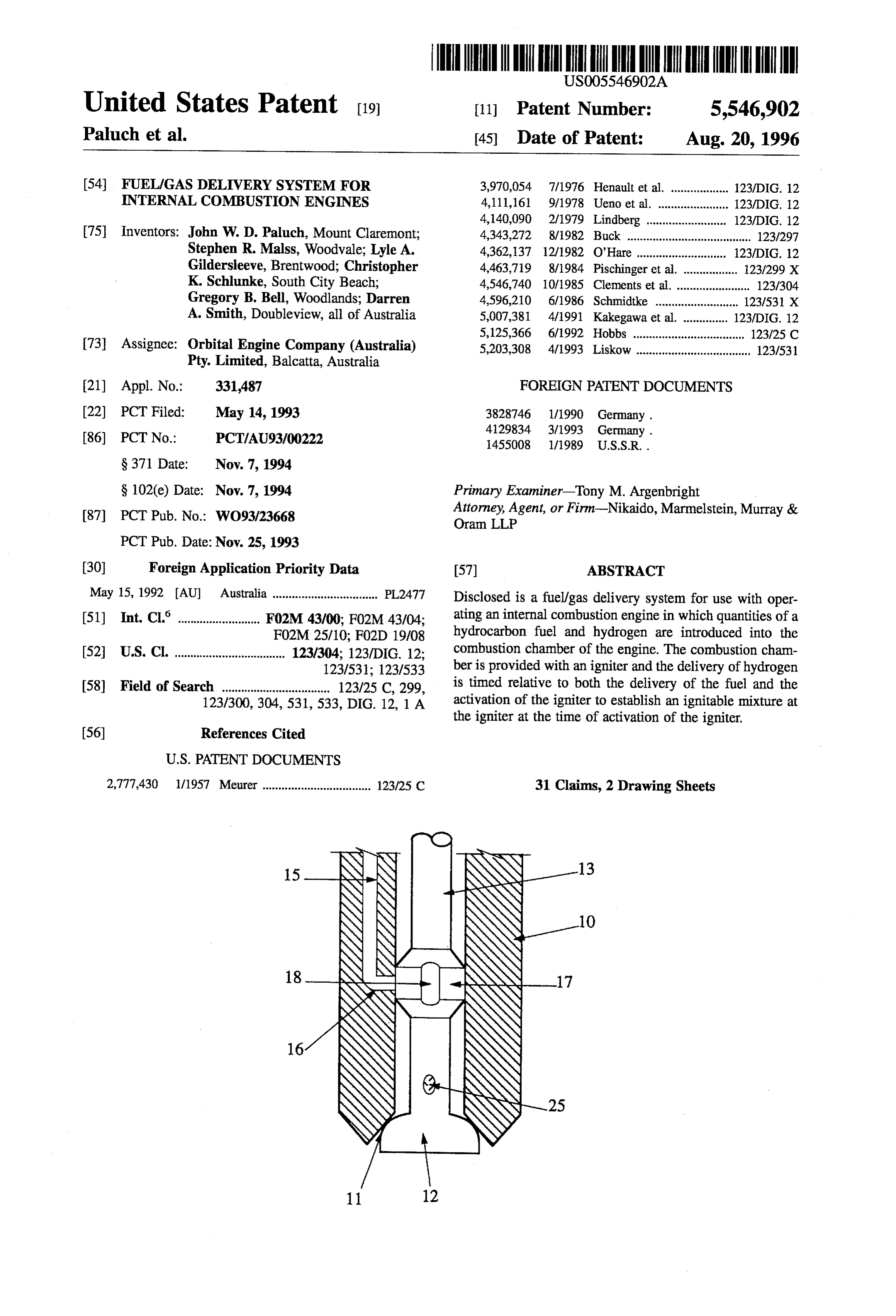
United States Patent (19) 11 Patent Number: 5,546,902 Paluch et al. 45) Date of Patent: Aug. 20, 1996 (54) FUEL/GAS DELIVERY SYSTEM FOR 3,970,054 7/1976 Henault et al. .................. 123/DIG. 12 INTERNAL COMBUSTION ENGINES 4,111,161 9/1978 Ueno et al. ...................... 123/DIG. 12 4,140,090 2/1979 Lindberg ... ... 123/DIG. 12 75 Inventors: John W. D. Paluch, Mount Claremont; 4,343,272 8/1982 Buck ....................................... 123/297 Stephen R. Malss, Woodvale; Lyle A. 4,362,137 12/1982 O'Hare ............................ 123/DIG. 12 Gildersleeve, Brentwood; Christopher 4,463,719 8/1984 Pischinger et al. ................. 23/299 X K. Schlunke, South City Beach; 4,546,740 10/1985 Clements et al. ....................... 123/304 Gregory B. Bell, Woodlands; Darren 4,596,210 6/1986 Schmidtke ......... ... 123/531 X A. Smith, Doubleview, all of Australia 5,007,381 4/1991 Kakegawa et al. .............. 123/DIG. 12 5,125,366 6/1992 Hobbs ................................... 123/25 C 73 Assignee: Orbital Engine Company (Australia) 5,203,308 4/1993 Liskow .................................... 123/531 Pty. Limited, Balcatta, Australia (21) Appl. No.: 331487 FOREIGN PATENT DOCUMENTS 22) PCT Filed: May 14, 1993 3828746 1/1990 Germany . 86 PCT No.: PCT/AU93/00222 4129834 3/1993 Germany.
S 102(e) Date: Nov. 7, 1994 Primary Examiner-Tony M. Argenbright 87). PCT Pub. No.: WO93/23668 Attorney, Agent, or Firm-Nikaido, Marmelstein, Murray & Oram LLP
(30) Foreign Application Priority Data 57 ABSTRACT May 15, 1992 AU Australia ................................. PL2477 Disclosed is a fuel/gas delivery system for use with oper (51) Int. Cl.' ......................... F02M 43/00; FO2M 43/04; ating an internal combustion engine in which quantities of a F02M 25/10; F02D 19/08 hydrocarbon fuel and hydrogen are introduced into the 52 U.S. Cl. ................................... 123/304; 123/DIG. 12; combustion chamber of the engine. The combustion cham 123/531; 123/533 ber is provided with an igniter and the delivery of hydrogen 58) Field of Search .................................. 123/25C, 299, is timed relative to both the delivery of the fuel and the 123/300, 304,531, 533, DIG. 12, 1 A activation of the igniter to establish an ignitable mixture at the igniter at the time of activation of the igniter.
2,777,430 1/1957 Meurer .................................. 123125 C. 31 Claims, 2 Drawing Sheets
Page 2
Drawing sheet — no readable text.
Page 3
Drawing sheet — no readable text.
Page 4
FUEL/GAS DELVERY SYSTEM FOR its location relative to the combustion chamber walls, the INTERNAL COMBUSTION ENGINES fuel entry to the combustion chamber, the sparkplug or like igniter, or the exhaust port. Thus, the ability to supply these
This invention relates to the combustion process of an substances to a particular location within the combustion internal combustion engine and particularly to the enhance chamber under particular engine operating conditions not ment of that process to reduce the level of exhaust emissions only contributes to the enhanced performance but also and/or improve combustion stability and/or otherwise reduces the consumption rate of the selected substance thus enhance the combustion process. increasing the cost effectiveness of the use of the selected All major industrial countries currently have regulations substance. The reference to 'substances is to be understood relating to the level of exhaust emissions from motor 10 to include specific elements, compounds of two or more vehicles, particularly passenger type vehicles. The control elements, or mixtures of elements and/or compounds. ling authorities are progressively reducing the permitted It is therefore the object of the present invention to level of emissions thereby increasing the demand for greater provide a method of operating an internal combustion control of the combustion process of internal combustion engine whereby the control of the combustion of the fuel/air engines. The regulations regarding the control of exhaust charge is enhanced to thereby assist in the control of the emissions apply a test procedure wherein engine operation at 15 level of vehicle exhaust emissions and/or improve combus low to medium load is typically a significant factor and tion stability and/or otherwise enhance the combustion pro unfortunately these areas of operation of the engine present cess in a manner which is both efficient and economic. a substantial difficulty in control of the combustion process. With this object in view there is provided a method of In the low to medium range of operation of an engine, the operating an internal combustion engine comprising deliv rate of fuel consumption is such that the distribution of fuel 20 ering a quantity of fuel into a combustion chamber of the within the air charge in the combustion chamber is prefer engine, and over at least a selected portion of the engine ably of a stratified nature so that a sufficiently rich mixture operating load range, injecting into the combustion chamber exists in the vicinity of the ignition device to provide reliable a quantity of a combustion control substance in timed initiation of combustion. The creation of the stratified fuel relation to said delivery of the fuel and establishing at a distribution is particularly difficult to achieve where the fuel selected location within the combustion chamber a selected is introduced into the air charge prior to the air charge fuel control substance distribution. entering the combustion chamber, particularly as the fuel Conveniently, the injection of the control substance is must be delivered into the air charge at a time related to the preferably also in a timed relation to the ignition of the fuel. engine cycle to ensure that all of the fuel reaches the combustion chamber before the inlet port is closed. Thus 30 The control substance can be an ignition enhancer there is a substantial time interval for the fuel to disperse in wherein the selected location is the immediate vicinity of an the air charge both in the air intake system and in the ignition means located within the combustion chamber combustion chamber before and after closing of the inlet thereby improving the ignitability of the fuel/air mixture in port. the combustion chamber. This improved ignitability is Some degree of success has been achieved in establish advantageous when the engine is operating at low loads ing a stratified charge by the use of a fuel injector to deliver 35 when the fuel/air mixture is lean and/or stratified. the fuel into the air charge at a location only a relatively Under other operating conditions, it can be desirable to short distance upstream from the inlet port. This permits deliver the control substance at a location adjacent the relatively late injection of the fuel and restricts the time peripheral wall of the combustion chamber, such as, for available for dispersion of the fuel within the air charge. example, an oxidant to assist in oxidation of hydrocarbons, Further improvement has been obtained by the injection of 40 or a knock suppressant including water or amonia. Also the the fuel directly into the combustion chamber. However, this control substance may be an additive to increase the octane introduces the further problem that the fuel must be injected rating of the fuel in order to control knock. at a near sonic velocity to achieve the necessary degree of More specifically, there is provided a method of operat atomisation of the fuel. Moreover, the high velocity also ing an internal combustion engine comprising delivery of results in a significant dispersion of the fuel within the 45 respective quantities of a fuel and an ignition enhancement combustion chamber. substance into a combustion chamber of the engine, the It has also been proposed to introduce an ignition combustion chamber having a selectively operable igniter enhancing substance together with the fuel/air charge to means located therein characterised in that said ignition assist in the promotion of initial ignition of the fuel. Hydro enhancement substance is delivered directly into said com gen is the preferred enhancing substance to be used in this 50 bustion chamber in timed relation to the delivery of the fuel, procedure, but, due to its high rate of dispersion, approxi preferably such that an enhanced ignitable mixture is estab mately 10 times faster than oxygen, relatively large quanti lished at the igniter means at the time of activation of the ties of hydrogen are consumed, particularly where the fuel igniter means.
and hydrogen are introduced into the air charge prior to the Preferably, the fuel is a hydrocarbon fuel and preferably delivery thereof to the combustion chamber. Also, as it is 55 the fuel is delivered directly into the combustion chamber desirable for practical reasons to produce the hydrogen either independently of, or together with, the ignition within the vehicle rather than merely to supply a reservoir of enhancement substance. Also, the combustion control sub pre-produced hydrogen, the large consumption of hydrogen stance is metered in accordance with engine operating necessitates a substantial "on-board” hydrogen generating conditions such as engine load and/or speed and/or in capacity which both consumes energy, occupies space in and relation to the rate of fuel supply to the engine. Preferably, adds weight to the vehicle. the combustion control substance is delivered to the com It is also known that the introduction of other selected bustion chamber only when the engine is operating in a substances into the fuel/air charge in the combustion cham selected load and/or speed range, such as the low to medium ber of an engine can be beneficial to the management of the engine load range.
combustion process. Furthermore, it is also known that the 65 Conveniently, the combustion control substance is deliv effectiveness of some of these substances is related to the ered into the combustion chamber entrained in a gas such as location of the substance within the fuel/air mixture such as air, either independent of or in conjunction with the fuel.
Page 5
Conveniently, the combustion control substance is to the engine. Preferably, the control substance delivery hydrogen or a hydrogen rich gas. Preferably, the commence means delivers only when the engine is operating in a ment of the delivery of the hydrogen to the combustion selected load and/or speed range, such as the low to medium chamber occurs later in the engine cycle than the com engine load range. The control substance delivery means mencement of delivery of the fuel, and can occur after the only delivers for the time that the relevant engine operating completion of the delivery of the fuel to the combustion condition subsists or cyclically. chamber. Because hydrogen has a high rate of dispersion, it Preferably, the control substance is hydrogen and the is preferable that the hydrogen is delivered at this time so delivery means delivers hydrogen to the immediate vicinity that there is sufficient time for the hydrogen to reach the of the igniter means in the combustion chamber, for vicinity of the igniter means and such that there is not 10 example, by a nozzle located in the cylinder head adjacent sufficient time for the hydrogen to disperse to such an extent the igniter means and may be incorporated in or mounted on that the ignitability enhancement effect of the hydrogen in the ignition means to direct a stream of hydrogen at an the fuel-air mixture is substantially lessened. electrode of the igniter means.
Preferably, the hydrogen is delivered into the combustion Where air is introduced to the fuel injection means by a chamber in such manner as to minimise the dispersion of the hydrogen and to direct the hydrogen to the immediate 15 compressor the hydrogen delivery means may conveniently vicinity of the igniter means. introduce hydrogen to the air at the compressor either at the In accordance with another aspect of the present inven inlet or outlet side thereof. Where a combustion air/fuel rail tion, there is provided a method of operating an internal is employed, the problem of introducing hydrogen to high combustion engine comprising injecting respective metered pressure air may be avoided by the utilisation of this means. quantities of a fuel entrained in air directly into an engine 20 The introduction of hydrogen with the fuel to the com combustion chamber, and characterised in that a combustion bustion chamber potentially results in a number of advan control substance, such as an ignition enhancement sub tages for the operation of the internal combustion engine. stance, for example hydrogen, is introduced into the air to These advantages arise from the improved ignitability of the provide a substantially uniform airlcontrol substance mix fuel/air mixture caused by introduction of hydrogen there ture for entrainment of the fuel. 25 with to the combustion chamber. Some of these advantages Preferably, the control substance is introduced into the air are as follows:
only when the engine is operating in a selected engine load 1. The airlfuel ratio is less critical to the ignitability of the and/or speed range, such as, for example, the low-medium charge and charges with air/fuel ratios up to as lean as load or speed range of the engine in the case of hydrogen, 40:1 at the igniter means can be acceptable or as rich as or in the high load and/or speed range of the engine in the 30 case of a knock control substance. The hydrogen or other 5:1 at the igniter means. control substance may be introduced into the air during the 2. The hydrocarbon (HC) and CO content of the exhaust time period that control substance is required or it may be gas is reduced.
introduced cyclicly, particularly when the control substance 3. Improved engine stability at low temperature operation is hydrogen as it has a sufficiently high dispersion rate to is achieved due to the improved ignitability of the provide a substantially uniform mixture before injection to 35 mixture.
the combustion chamber.
The invention also provides, in another aspect, an appa 4. It is not necessary to select an ignition timing dictated ratus for delivering fuel to an internal combustion engine by the requirements of ignitability and thus the spark comprising a fuel injection means operable to inject inde advance may be set at a minimum for best torque pendent metered quantities of fuel entrained in air into a 40 (MBT). This spark setting also contributes to the reduc combustion chamber of the engine, the fuel injection means tion of NOx and improved fuel consumption. being communicable with the combustion chamber through 5. Usage of hydrogen has been found to enable a greater a selectively openable delivery port, a selectively operable use of Exhaust Gas Recirculation (EGR) for the reduc igniter means located in the combustion chamber to ignite tion of emissions. The Exhaust Gas Recirculation the fuel, and a combustion control substance delivery means 45 (EGR) method is disclosed in Orbital Engine Company to deliver a combustion control substance directly to the Pty. Limited's International Application WO94/16207. combustion chamber in timed relation to the injection of the As the present invention enables the injection of the fuel. hydrogen directly into the combustion chamber, which Conveniently, the control substance is delivered to the injection event preferably occurs independently of the fuel combustion chamber in admixture with air, 50 delivery, it has been found that only relatively small amounts In one alternative construction the control substance of hydrogen are required to achieve the desired improve delivery means may be arranged to deliver a control sub ment in the ignitability of the fuel/air mixture, even in stance to the fuel injection means whereby the control stratified charge engines. Substantial improvement in the substance and the fuel are delivered entrained together in air combustion process has been achieved with as little as 2% to the combustion chamber. 55 hydrogen injection in relation to the fuel charge. This In another alternative, the control substance delivery contrasts with the prior art where it was discovered that means delivers independently and directly to the combustion when the hydrogen is introduced to the air charge prior to chamber. However, the control substance delivery means is entering to the combustion chamber, hydrogen requirements activated in timed relation to the activation of the fuel as high as 10% or more were necessary to obtain the same injection means and conveniently by the same activating 60 improvements in the combustion process. The low hydrogen mechanism as the fuel injection means. usage enabled by the invention enhances the possibility of The control substance delivery means is desirably pro providing an economical means of producing sufficient vided with metering means to meter the quantity of the quantities of hydrogen on-board a vehicle, perhaps by using control substance delivered to the fuel injection means or a compact catalytic process.
combustion chamber. Such metering may be operable in 65 The invention will be more readily understood from the accordance with engine operating conditions, such as engine following description of several practical embodiments of load and/or speed and/or in relation to the rate of fuel supply the control supply of hydrogen to the engine combustion
Page 6
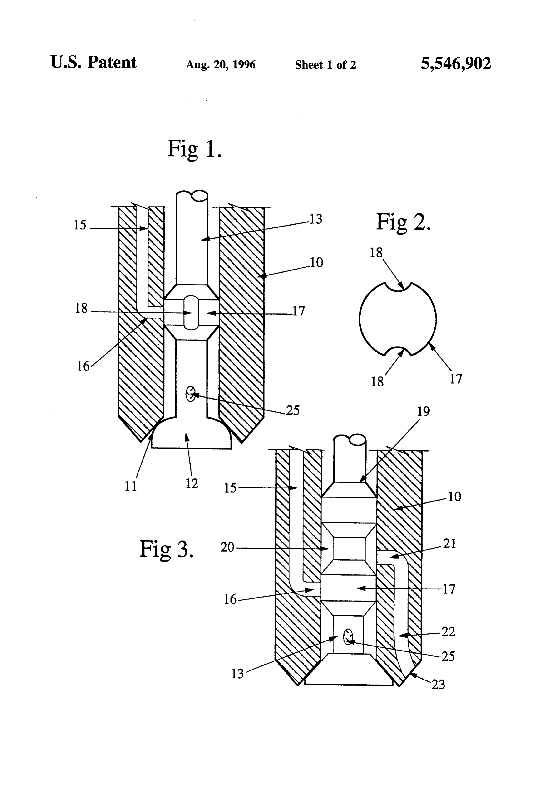
S 6 chamber and with reference to the accompanying drawings. groove or grooves 18 may be employed. Therefore, when the It is to be understood that although the following description valve member 12 is open, hydrogen passes through the with reference to the drawings is specifically related to the grooves 18 and subsequently open outlet port 11. delivery of hydrogen to the combustion chamber the same By suitable selection of the dimensional relationship of general construction can be used to deliver other combustion the enlarged portion 17 with respect to the bleed port 16 and control substances to the combustion chamber and to direct the valve member 12, various timed relationships can be that control substance to appropriate locations within the obtained between the opening and closing of the outlet port combustion chamber. 11 of the nozzle and the opening and closing of the bleed In the drawings, port 16. In the preferred arrangement, the bleed port 16 is FIG. 1 is a cross-sectional side view of a portion of a fuel 10 open for a shorter interval of time than the outlet port 11. injector nozzle incorporating hydrogen supply means; Furthermore, the opening of the bleed port 16 is preferably FIG. 2 is a schematic diagram illustrating the cross delayed with respect to the opening of the outlet port 11. In sectional geometry of the enlarged portion of the valve stem this way, the hydrogen gas is delivered to the combustion as shown in FIG. 1; chamber later than the fuel and there is thus less time FIG. 3 is a cross-sectional side view of a fuel injector 15 available for dispersion of the hydrogen prior to ignition of nozzle with an alternative form of hydrogen supply means; the fuel/hydrogen/air mixture.
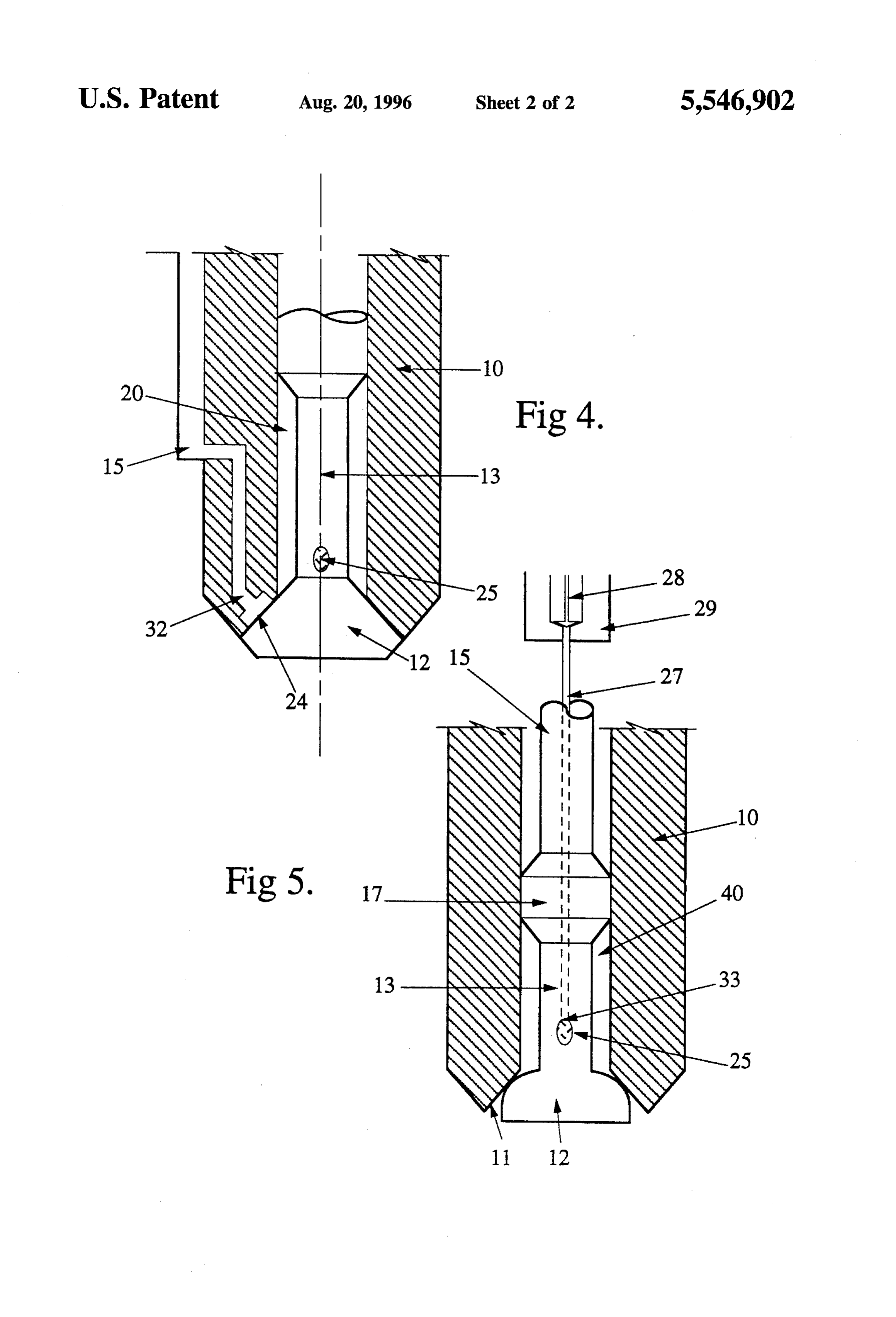
FIG. 4 is a cross-sectional side view of a fuel injector FIG. 3 shows a modification to the construction in FIG. 1 nozzle incorporating a further form of hydrogen supply whereintwo enlarged portions 17 and 19 are provided on the means; and valve stem 13, with each of the enlarged portions 17 and 19 FIG. 5 is a cross-sectional side view of a fuel injector 20 being in contact with the internal surface of the bore of the nozzle incorporating a still further form of hydrogen supply nozzle body 10 about the complete periphery of the respec CaS. tive enlarged portions 17 and 19. In this way, an isolated Referring now to FIG. 1 of the drawings, the construction chamber 20 is provided between the enlarged portions 17 of the fuel delivery nozzle incorporating a hydrogen supply and 19. In addition to the bleed port 16 in the wall of the means comprises a hollow cylindrical body 10 having an 25 nozzle body 10, there is, in this embodiment, provided afuel outlet port 11 at the lower extremity thereof and a valve delivery port 21 connected by the passage 22 to the injection member 12 mounted on a valve stem 13. The valve member port 23.
12 is selectively movable to open and close the outlet port It can thus be seen that in this alternative construction, the 11 for the delivery of a fuel/air mixture. The movement of hydrogen is delivered from a separate delivery port 21 to the the valve member 12 to open and close the outlet port 11 is 30 injection port 23 which is appropriately located to direct the normally effected by a selectively energisable solenoid hydrogen to the area of the spark plug located within the under the control of an ECU as is well known in the fuel combustion chamber to promote the formation of an ignit injection art. able mixture in the immediate vicinity thereof. The timing of The nozzle body 10 has a passage 15 provided in one wall the delivery of the hydrogen may also be delayed, at least thereof which communicates with a hydrogen supply (not 35 with respect of the commencement of the delivery of the fuel shown) and which terminates in a bleed port 16 in the to the combustion chamber as previously described. internal wall of the nozzle body 10. The valve stem 13 has It will also be understood that passage 22 and port 23 may an enlarged portion 17 of a diameter selected to ensure a be located and configured to deliver the hydrogen in a wide close sliding fit within the bore of the body 10. The enlarged range of directions depending upon where it is desired to portion 17 provides a support for the valve stem 13, centrally 40 concentrate the hydrogen or other combustion control sub in the bore of the nozzle body 10, particularly when the stance within the combustion chamber. In particular the valve member 12 is in the open position. The enlarged combustion control substances may not be required to be portion 17 is not required to be in contact with the internal concentrated in the vicinity of the spark plug of the com surface of the nozzle body 10 about the whole periphery bustion chamber.
thereof, and may be in such contact at a plurality of locations 45 In both of the above described constructions, the fuel about the periphery of the nozzle body 10 so as to centrally preferably passes through the valve stem 13 which is of a locate the valve stem 13 within the bore. hollow construction and has one or more outlet apertures 25 However, the enlarged portion 17 of the valve stem 13 is in the area immediately above the valve member 12 and in a close sliding contact with the internal surface of the bore below the enlarged portion 17.
of the nozzle body 10 in the area where the bleed port 16 is 50 Another construction is shown in FIG.4, which illustrates located so as to provide control over the opening and closing a nozzle wherein hydrogen travels through passage 15 and of the bleed port 16. Therefore, the contact between the orifice 32 to the cavity 24 thus to be injected to the enlarged portion 17 and the internal surface of the nozzle combustion chamber of an engine with minimal mixing of body 10 is arranged so that when the valve member 12 is in fuel, air and hydrogen prior to injection. the closed position, the bleed port 16 will also be closed by 55 In a further modification, as shown in FIG. 5, the hydro the engagement of the enlarged portion 17 with the internal gen may be delivered through a separate passage 27 and surface of the bore of the nozzle body 10, thus preventing the associated control valve 28, such as a solenoid actuated flow of hydrogen through bleed port 16 into the bore of valve, in a metering unit 29, which controls the timing and nozzle body 10. duration of the delivery of the hydrogen. In the construction Further, the enlarged portion 17 is proportioned so that shown, hydrogen travels through a needle-like body having when the valve member 12 is moved to the open position, formed therein the fuel supply passage 27 to an exit point 33 the bleed port 16 is exposed so that hydrogen available in the aligned with the outlet aperture 25. In this way, mixing of passage 15 is enabled to flow into a lower portion of the hydrogen with air passing either through the interior of the internal bore of the nozzle body 10 via a groove or grooves hollow nozzle body 10 or valve stem 13 is prevented until 18, formed in the enlarged portion 17 of the valve stem 13. 65 injection. Alternatively, the hydrogen can be delivered to the Two grooves 18 are shown in FIG. 2. Nonetheless, it should combustion chamber of the engine separately from the fuel be apparent that any suitable number or geometry of the in a manner similar to that described with reference to FIG.
Page 7
3 or delivered directly through the bore of the nozzle body claimed in claim 1 or 2 wherein the combustion control 10 for delivery to the combustion chamber of the engine substance is delivered into the combustion chamber through the fuel injector nozzle, as described with reference entrained in air.
to FIG. 1. 5. A method as claimed in claim 1 or 3 wherein the Also the valve 28, metering unit 29 and passage 27 can be combustion control substance is injected into the combus arranged at any desired location relative to the combustion tion chamber admixed with air and the fuel. chamber depending on the desired location of the combus 6. A method as claimed in claim 1 or 3 wherein said tion control substance within the combustion chamber. Thus, combustion control substance is delivered to said combus for example, it may be located adjacent the spark plug or be tion chamber when the engine is operating in a low to incorporated in the body of the spark plug. O medium engine load range.
Further, where the fuel is delivered to the combustion 7. A method as claimed in claim 1 or 3 characterised in chamber entrained in air, the air can be supplied through the wherein said delivery of the combustion control substance to central axial bore 40 of the cylindrical nozzle body 10 of a said combustion chamber is effected a sufficient time before fuel injector nozzle of the construction as previously ignition such that said control substance reaches the imme described with reference to FIGS. 1 and 3. In such fuel 15 diate vicinity of an igniter means located within said com injection systems, the hydrogen can be delivered into the air bustion chamber prior to ignition.
at a location upstream from the fuel injector, by a suitably 8. A method as claimed in claim 1 or 3 wherein said controlled valve such as a solenoid actuated valve, operated combustion control substance is delivered directly to the by a suitably programmed ECU. Although this proposal combustion chamber in an immediate vicinity of an igniter results in the hydrogen being available for dispersion in the 20 means located within said combustion chamber prior to air for a greater time period than in the embodiments of ignition.
FIGS. 1 and 3, the quantity of air is substantially less than 9. A method as claimed in claim 1 or 3 wherein the is available when the hydrogen is delivered into the air combustion control substance is an ignition enhancer. induction manifold or otherwise introduced into the induc 10. A method as claimed in claim 9 wherein the ignition tion air. 25 enhancer is hydrogen.
It is not intended that the invention be limited to hydrogen 11. A method in claim 1 or 3 wherein hydrogen is in its pure state or even in admixture with other gases. The delivered to the combustion chamber during at least one of principles discussed above are equally applicable to the engine start-up or acceleration. injection of any other gases that can, for example, be used 12. A method of operating an internal combustion engine to improve combustion stability and/or otherwise enhance 30 comprising injecting respective metered quantities of fuel the combustion process such as by reducing the tendency to entrained in air directly to an engine combustion chamber knock or reduce emissions. As examples may be mentioned and characterised in that a combustion control substance is nitrogen/recycled exhaust gas mixtures, oxygen and mix introduced into said air to provide a substantially uniform tures containing oxygen. Mixtures of hydrogen and other air/combustion control substance mixture for entrainment of appropriate gases may also be utilised. 35 the fuel.
It is also to be understood that the supply of hydrogen or 13. A method as claimed in claim 12, wherein said other combustion control substances can be controlled in combustion control substance is introduced into said air respect of quantity delivered per combustion chamber per when said engine is operating in at least one of a selected cycle thereof, such as by the ECU control of the metering engine load and speed range.
unit 29. Thus, where a hydrogen production facility is 40 14. A method as claimed in claim 13, wherein said provided on board the vehicle, the hydrogen may be stored selected range is a low to medium engine load or speed and metered to the engine as required by engine operating range.
conditions, such as during acceleration or cold start where 15. A method as claimed in claim 12 wherein said air for hydrocarbon production is high. entrainment of said fuel is supplied by a compressor and said We claim: 45 combustion control substance is introduced into said air at 1. A method of operating an internal combustion engine said compressor.
comprising directly injecting a quantity of fuel entrained in 16. A method as claimed in claim 15 wherein the com air into a combustion chamber of an engine, and over at least bustion control substance is introduced into said air on the a selected portion of the engine operating load range deliv outlet side of said compressor.
ering into the combustion chamber a quantity of a combus 50 17. A method as claimed in claim 12 wherein said tion control substance in timed relation to said injecting of combustion control substance is an ignition enhancer. the fuel and establishing at a selected location within the 18. A method as claimed in claim 17 wherein the ignition combustion chamber a selected combustion control sub enhancer is hydrogen.
stance distribution. 19. An apparatus for delivering fuel to an internal com 2. A method as claimed in claim 1 wherein said combus 55 bustion engine comprising a fuel injection means operable to tion control substance is delivered to said combustion cham inject independent metered quantities of fuel entrained in air ber only when the engine is operating in a selected load and into a combustion chamber of the engine, the fuel injection speed range. means being communicable with the combustion chamber 3. A method of operating an internal combustion engine through a selectively openable fuel delivery port, and com comprising delivering a quantity of fuel into a combustion 60 bustion control substance delivery means to deliver a com chamber of the engine; and, only over a selected portion of bustion control substance to the combustion chamber in the engine operating load range delivering into the combus timed relation to the injection of the fuel. tion chamber a quantity of a combustion control substance 20. Apparatus as claimed in claim 19 wherein said com bustion control substance delivery means is adapted to in timed relation to said delivery of fuel and establishing at a selected location within the combustion chamber a 65 deliver said control substance to said fuel injection means selected combustion control substance distribution. prior to delivery thereof to said combustion chamber. 4. A method of operating an internal combustion engine as 21. Apparatus as claimed in claim 19 wherein said deliv
Page 8
ery means is operable in timed relation to the opening of said therethrough communicating with the axial bore adjacent the fuel delivery port. port, said stem being axially movable in its bore to open and 22. Apparatus as claimed in claim 19, wherein said close the valve.
delivery means and said fuel delivery port are operated by 27. Apparatus as claimed in claim 26 wherein said control the same activating means. substance delivery means is selectively communicated with 23. Apparatus as claimed in claim 19, wherein said said axial bore in response to the opening of the port to control substance delivery means is adapted to deliver said deliver a combustion control substance into said bore. control substance in response to the engine operating in at 28. Apparatus as claimed in claim 26 wherein said control least one of a selected load and speed range. substance delivery means includes a further passage in said 24. Apparatus as claimed in claim 19, wherein said 10 body of said fuel injection means communicating with the control substance delivery means is adapted to deliver said combustion chamber, and means are provided to selectively control substance to the immediate vicinity of igniter means open and close said further passage in timed relation to the provided in said combustion chamber. opening and closing of the port. 25. Apparatus as claimed in claim 24, wherein said 29. Apparatus as claimed in claim 28 wherein said further control substance delivery means is at least one of incorpo 15 passage delivers a combustion control substance to the rated in and mounted on said igniter means. combustion chamber in the vicinity of an igniter means. 26. Apparatus as claimed in claim 19, wherein said fuel 30. Apparatus claim 19 wherein the combustion control injection means includes a body having an axial bore substance is hydrogen.
connectable to an air supply and connected at one end to said 31. Apparatus as claimed in claim 26 wherein the com fuel delivery port, a valve operable to open and close the port 20 bustion control substance is hydrogen. and a valve stem attached to the valve and extending within the axial bore, the valve stem having an axial fuel passage k k sk. k. k.
Provenance
- Collection
- Cited prior art
- Original PDF
- patentimages.storage.googleapis.com →
- Filed
- 1993-05-14
- Pages
- 8
- Method
- pdftotext (the PDF's own text layer) + pdftoppm 300dpi page scans
- Source
- Google Patents bibliographic record
- Granted
- 1996-08-20
- Inventors
- John W. D. Paluch; Stephen R. Malss; Lyle A. Gildersleeve; Christopher K. Schlunke; Gregory B. Bell; Darren A. Smith; Orbital Engine Co Australia Pty Ltd
- Transcribed from
- patentimages.storage.googleapis.com →