patent · US4596210
Method and device for dissolving gas, especially carbon dioxide, in liquid fuel and for distributing the fuel in a supersaturated state through the combustion air
24 June 1986
Page 1 — bibliographic record
United States Patent (19) 11 Patent Number: 4,596,210 Schmidtke (45) Date of Patent: Jun. 24, 1986 54 METHOD AND DEVICE FOR DISSOLVNG 4,273,560 6/1981 Kostka.................................... 123/3 GAS, ESPECIALLY CARBON DIOXIDE, IN 4,336,783 6/1982 Henson .. . 261/DIG. 83 LIQUID FUEL AND FOR DISTRIBUTING 4,343,282 8/1982 Glenn .................................. 123/523 THE FUEL IN A SUPERSATURATED STATE 4,362,137 12/1982 O'Hare .................................... 123/3 THROUGH THE COMBUSTION AIR 4,429,674 2/1984 Libbing.............................. 123/531 4,483,307 11/1984 Gilmor ........................ 261/DIG. 83 (75) Inventor: Wolfgang Schmidtke, Paderborn, OTHER PUBLICATIONS Fed. Rep. of Germany (73) Assignee: Kohlensaurewerke C. G. Bak"Liquid Petroleum Gasifier Replaces Carburetor', Rommenholer GmbH, Bad 3/1981, New Design Ideas.
Driburg-Herste, Fed. Rep. of Primary Examiner-E. Rollins Cross
Germany Attorney, Agent, or Firm-Sprung Horn Kramer & (21) Appl. No.: 605,030 Woods 22 PCT Filled: Aug. 31, 1983 57 ABSTRACT (86) PCT No.: PCT/EP83/00228 Method and device for dissolving gas, especially carbon dioxide or compressed air, in liquid subject to condi
S371 Date: Apr. 25, 1984 tions of pressure and temperature at which, when the S 102(e) Date: Apr. 25, 1984 solution is subsequently introduced into the combustion (87) PCT Pub. No.: WO84/00996 air, it will be in a supersaturated state and accordingly finely disperses and distributes itself uniformly. The fuel
PCT Pub. Date: Mar. 15, 1984 is forced by a pump (41) into the mixer (11), to which (51) Int. Cl." .............................................. FO2B 75/12 the gas is supplied through a flow regulator (29). Down (52) U.S. C. ....................................... 123/1 A; 123/3; stream of the mixer (11) are a turbulent section (163), a 123/531 mixing dome (161), and an exhaust section (164) from (58) Field of Search ................... 123/1 A, 3, 575, 576, which the solution is supplied free of bubbles to the 123/522, 523, 531; 48/189.4; 261/DIG. 83,76, carburetor or injector of an internal-combustion engine, 78 R a heating burner, or a reaction-engine burner. The flow regulator (29) is controlled in accordance with the
throughput of fuel and regulated by a regulation device
(R) in accordance with the percentage of gas in the 1,465,574 8/1923 Bannister ............................ 123/523 mixing dome (161) as determined by a pressure gauge 2,114,548 4/1938 Stadlman ............................. 123/531 (46) or light sensor (51).
2,745,251 5/1956 Schirmer ............................. 123/531 4,011,847 3/1977 Fortino ....................... 261/DIG. 83 14 Claims, 7 Drawing Figures
Page 2
Drawing sheet — no readable text.
Page 3
Drawing sheet — no readable text.
Page 4
Drawing sheet — no readable text.
Page 5
purposed can in particular be dissolved if the fuel is
METHOD AND DEVICE FOR DISSOLVING GAS, saturated subject to a pressure of several atmospheres. ESPECIALLY CARBON DIOXIDE, IN LIQUID A switchover or mixing operation with various gases, FUEL AND FOR DISTRIBUTING THE FUEL INA carbon dioxide for example when starting or at low SUPERSATURATED STATE THROUGH THE 5 temperatures and air for continuous operation, yields a COMBUSTION AR practical combination with respect to the technical action and economics of the material input. The intro
The invention relates to a method of distributing duction of carbon dioxide can be relatively increased liquid fuel in combustion air that the fuel is mixed into even when operation conditions are aggravated, so that through a carburetor or injector. 10 a tendency to knock develops.
It is known that liquids that have gases dissolved in The device for dissolving the gas is a closed unit that them will spontaneously release the dissolved gas and is always simple to introduce into the fuel line. In one foam up or, when simultaneously atomized, break down practical embodiment the device is controlled subject to into fine droplets when the ambient pressure drops internally obtained criteria with respect to fuel flow and suddenly or the temperature increases rapidly leading to 15 the resulting saturation.
a state of supersaturation because of the lower solubility When the flow oscillates widely, in engines for exam of the gases at lower pressure or higher temperature. ple, the existing control criterion of the fuel-flow regu Distributing liquid fuels in combustion air by atom lator is exploited in a practical way to control the de ization and partial evaporation through heating and vice for saturation.
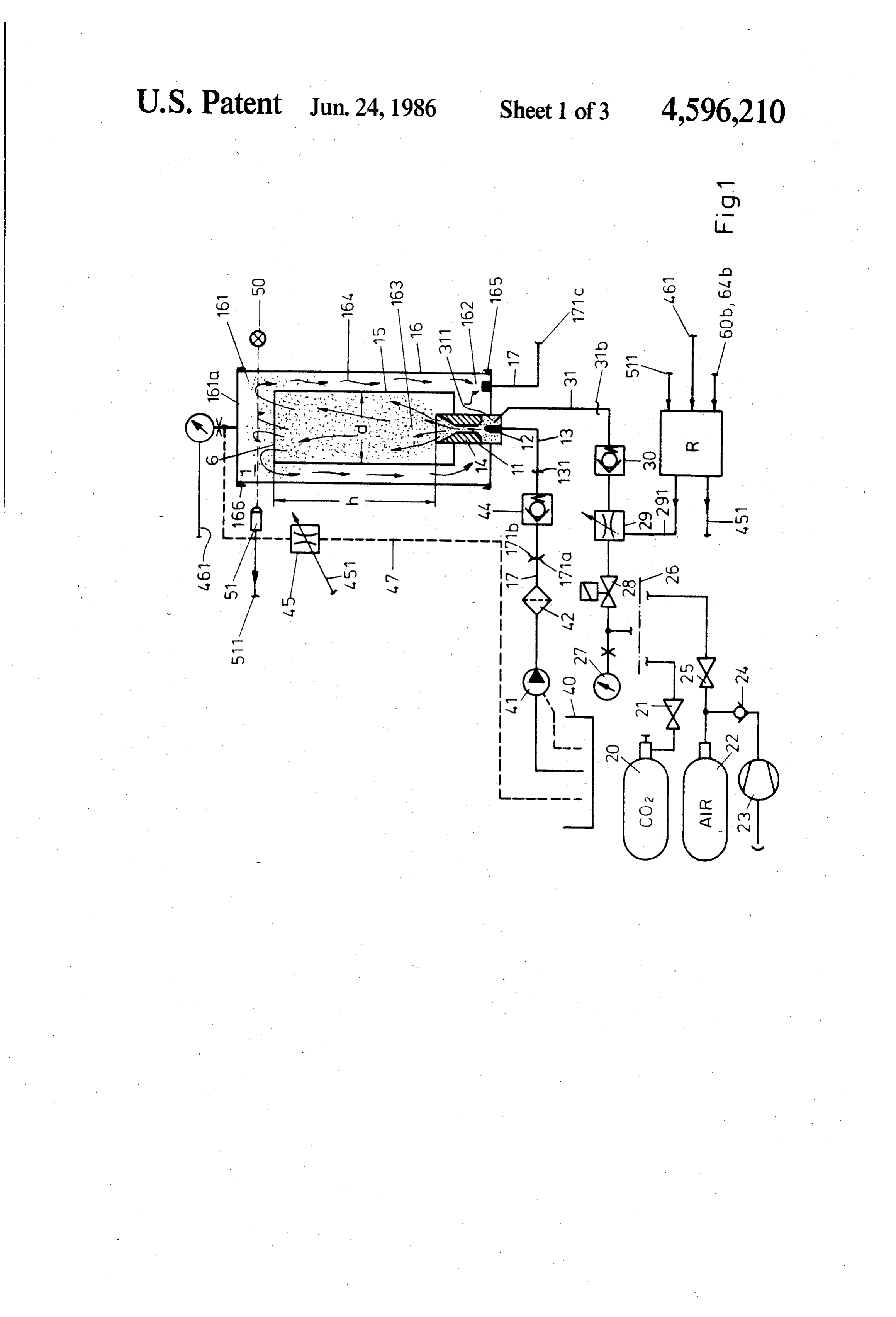
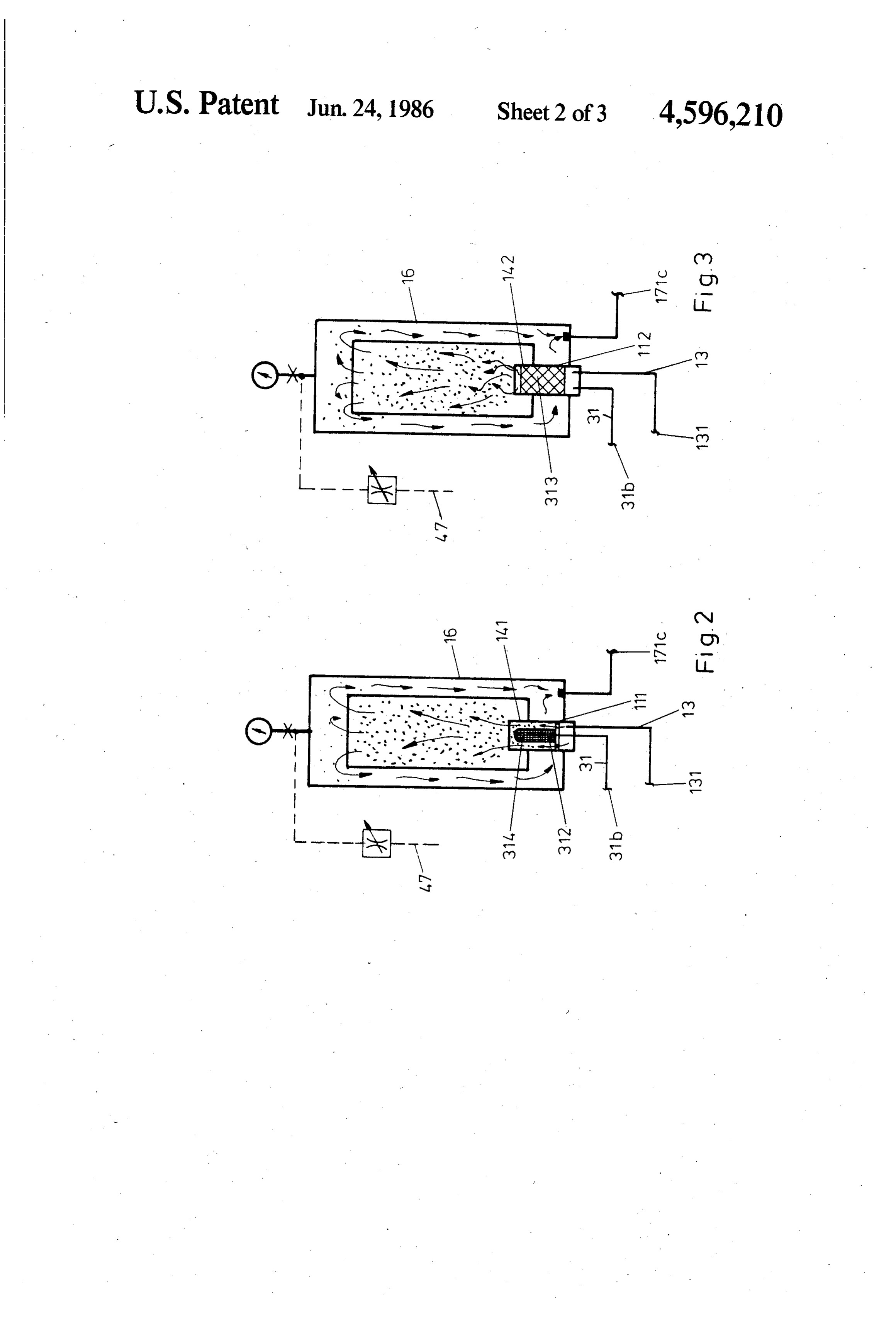
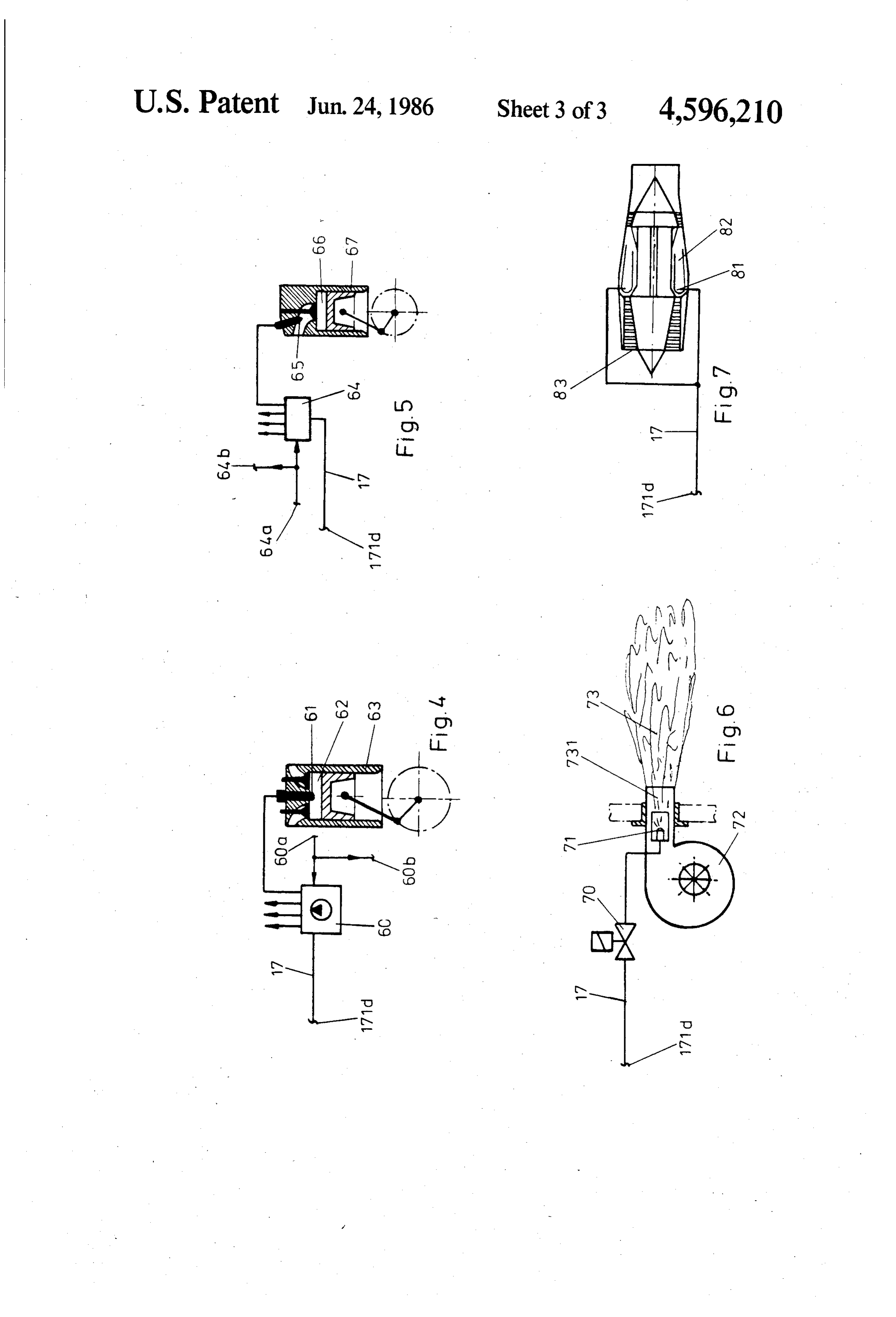
turbulence is on the other hand also known. These mix 20 A device for carrying out the method and how it can ing procedures all apply downstream of what is called be installed in known internal-combustion engines and the carburetor or the injector nozzles in that they are systems is illustrated in FIGS. 1 through 7. intended to employ zones of turbulence and a special FIG. 1 is a schematic representation of a device for design and disposition of the combustion or explosion 25 dissolving gases in fuel, space to supply the fuel or mixture of fuel and air. Since in FIG. 2 illustrates an alternative mixer for the device
none of these measures, however, are sufficient to attain a completely uniform and very fine distribution of fuel, FIG. FIG. 3 illustrates another mixer for the device in some of the fuel leaves the combustion space uncom 1, busted or separated in the form of carbon monoxide or 30 connected FIG. 4 illustrates how the device in FIG. 1 can be carbon or else, when an excess of air is supplied, the to a diesel engine, V excess is fruitlessly consumed to form nitrogen monox connected FIG. 5 illustrates how the device in FIG. 1 can be ides and injurious exhaust is released. to an injection engine, FIG. 6 illustrates
The object of the present invention is to disclose a connected to a heating how the device in FIG. 1 can be method and a device for distributing fuel in combustion 35 FIG. 7 illustrates howburner, and the device in FIG. 1 can be air essentially more uniformly and finely, diminishing connected to a reaction engine.
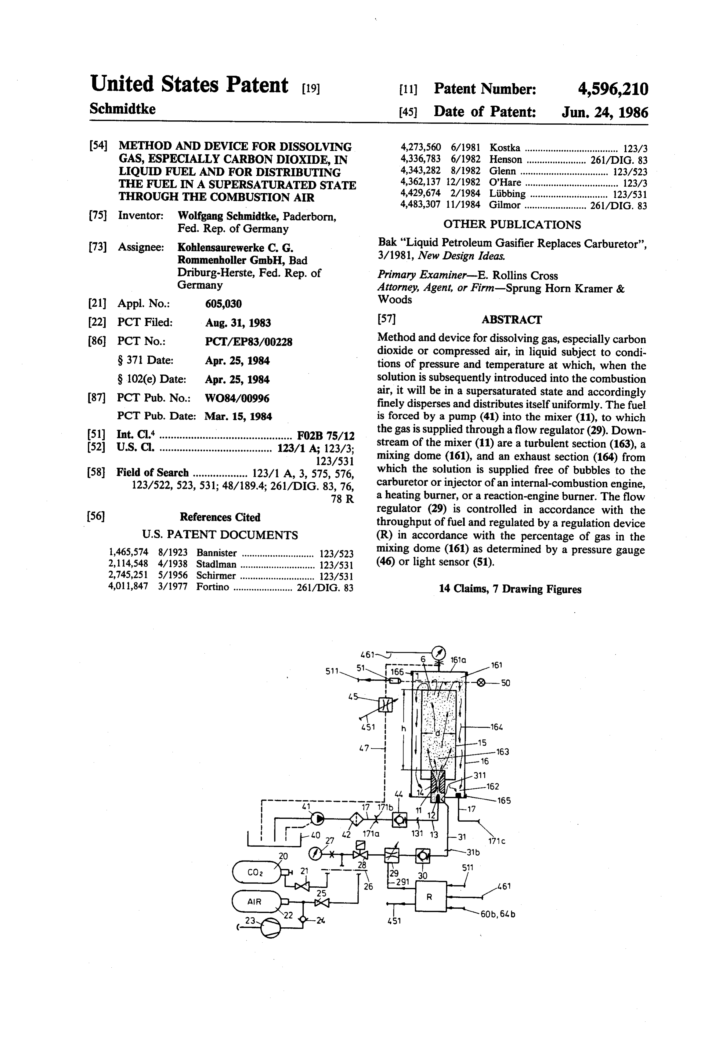
the drawbacks of the known methods and achieving The device for dissolving gases in fuels illustrated in improved combustion at higher efficiency, less injurious FIG. 1 consists of an injector-mixer 11 with a nozzle 12 exhausts, reliable sparking, and hence fewer problems in to which starting engines and a lower tendency for engines to surroundedfuelbyisa supplied over a line 13. Nozzle 12 is mixing chamber 311 into which the knock.
This object is attained in accordance with the inven suppliedgas, compressed air or carbon dioxide in this case, is tion in that gas, preferably air and/or carbon dioxide is which theover a line 31. An upright cylindrical pipe 15 in bubbles of gas dissolve in the fuel in a turbu dissolved in the fuel, at a state of dissolution pressure lent section 163 is connected and temperature at which a higher gas solubility of the 45 15 is dimensioned in a practicaltoway injector-mixer 11. Pipe such that the height gas is ensured than at the state of mixing pressure and h of turbulent section 163 is approximately twice the temperature of the combustion air during admixture, in diameter d so that the bubbles of gas will be practically a quantitative ratio such that the saturation-quantity completely dissolved during maximum fuel throughput ratio is exceeded at the state of mixing pressure and when they arrive at the top. Undissolved gas accumu temperature and the solution supplied to the carburator 50 lates in a mixing dome 161 above the top of pipe 15. A or injector. housing 16 extends down concentric with pipe 15 from The method can be employed for both explosive and mixing dome 161. The diameter of housing 16 is such continuous combustion systems. Various solutions of that at maximum throughput the falling speed of the gas and fuel can be employed depending on the applica fuel is lower in an exhaust section 164 between housing tion. 55 16 and pipe 15 than the rising speed of any residual gas When employed in connection with partial-vacuum bubbles still present. A fuel line 17 is connected to the carburetors, for instance, it is practical to dissolve a gas bottom of housing 16 and leads to what is called the of high solubility, carbon dioxide for example, in the carburetor or injection devices. gasoline.
It is furthermore practical to employ hydrogen, espe 60 of glass to 16
Housing is made out of glass or at least partly out allow optimum monitoring of the correct cially as a sparking aid, when burning difficult-to-burn flow regulation of the amount of gas employed. liquids like diesel oil or heavy oil.
When burning fuels with a relatively high carbon 42The fuel is conveyed from a tank 40 through a filter by means of a pump 41 in a known way and under content, benzene for example, the dissolution of oxygen pressure along fuel line 17.
is practical. 65 Between a connection 171a, which is connected to Minimum supply-technology expenditure is ensured connections 171b and 171c and to which in known en by using compressed air generated on site by a rela gines and combustion systems is connected to a connec tively small compressor. Enough air for the intended tion 171d (FIGS. 4-7), and, the device is furnished with
Page 6
a check valve 44 built into lines 17 and 13 in a practical FIG. 3 illustrates another embodiment of a mixer 112 way to maintain constant pressure in housing 16 in that consists of a known static mixer with a mixing order to maintain the saturation state of the fuel. chamber 313 that the gas and fuel is supplied to. Carbon dioxide is supplied to a mixing line 26 from a The particular type of mixer 11, 111, or 112 to be pressure tank 20 over a reduction valve 21 and a reser selected depends practically on the combination of gas voir 22 on the other hand filled with compressed air by and fuel selected and on their properties, especially with a compressor 23, the air also being supplied to mixing respect to contamination or blockage of the pores or line 26 through a reduction valve 25. A compressed-air nozzle. Another criterion, if the throughputs ever vary system of this type is already present in, for example, to a considerable extent, is miscibility. trucks. Because of the relatively small need for air, it is 10 The connections in the devices illustrated in FIGS. 2 sufficient in an automobile to charge a reservoir with a and 3 are similar to those in FIG. 1. compressor when fuel is purchased or a small separate The gases are generally dissolved subject to an initial compressor can be provided. pressure of about two atmospheres, higher pressures A manometer 27 monitors the pressure in mixing line being preferred. When, however, what is called the 26. A valve 28 opens, subject to an operating signal, 15 carburetor of a carburetor engine, which can not be mixing line 26 to a flow regulator 29, from which a line subjected to partial vacuum, is positioned downstream 31 leads to a injector-mixer 11 over a check valve 30. of the device, a readily soluble gas like carbon dioxide The function of these components can also be inte must be employed for saturation. In this case, partial grated into special subassemblies depending on their vacuum will produce a state of supersaturation in what design. Thus, when flow regulator 29 is firmly closed in 20 is called a carburation process and will lead to a finer the non-operating state, there is no need for a separate distribution of the fuel and, when the mixture of fuel valve 28. Furthermore, reservoir 22 can be left out and air is subsequently heated by heating from the cylin when a special, constantly following, compressor 23 is der wall, more gas will be released accompanied by the provided. To the extent that this compressor can be droplets breaking up.
controlled it can also assume the function of flow regu 25 FIG. 4 illustrates how the device can be employed in lator 29. a diesel engine 63. A solution of diesel oil and air or When a constant flow of fuel is necessary, as in heat carbon dioxide is saturated at about 10 atmospheres and ing burners for instance, the flow regulator can be set conveyed to an injector pump 60, whence it arrives in a once, by observing the dissolution of the bubbles before combustion chamber 62 through an injector nozzle 61. arriving at mixing dome 161 for example. Monitoring 30 Since the compressed air, which is also heated by the can however also be carried out with a pressure gauge cylinder wall in certain cases, has a high temperature, 46 or gas-bubble sensor like a float or, as illustrated, a the solubility of the gas will be exceeded in spite of the light barrier 50, 51, which also affords the possibility of high pressure, and the solution will be finely atomized controlling flow regulation automatically. In so doing, by the emerging gas. This significantly improves the signal line 461 or 511 is supplied to a regulation device 35 cold-starting properties in particular, so that saturation R and the signal compared with a predetermined value with the readily dissolving carbon dioxide is to be rec that corresponds to the presence of a lower flow of ommended for starting. When the engine is warm, satu bubbles as compared with the flow at the output of ration with air is adequate for improved efficiency and injector-mixer 11 and controlled by a differential signal reducing the destructive exhausts and soot formation. from flow regulator 29 over a line 291. 40 Valves 21 and 25 are reversed in accordance with When fuel consumption varies considerably it is an motor temperature for carbon dioxide and compressed advantage to provide a return line 47 from mixing dome air in a practical way.
161 to tank 40 through another flow regulator 45. Flow The flow of gas is regulated, meaning that flow regu regulator 45 is opened when a gas bubble that is large in lator 29 is controlled, when a control signal from regu relation to normal operation has accumulated in mixing 45 lation device R is supplied over a signal line 60b from a dome 161, as results from comparison of the signal from flow-regulation control line 60a to injector pump 60 or light barrier 50 and 51 with an accordingly high refer to flow regulator 29 directly.
ence value by automatic regulation over line 451. FIG. 5 illustrates an injection engine 67. The satu The flow of quantities of gas can also be controlled rated solution is supplied to its fuel-flow divider 64 and depending on fuel throughput by means of a given flow 50 thence conveyed to an injector nozzle 65. Since the regulation signal to the input lines 60b, 64b of regulation combustion air that is simultaneously suctioned up has a device R to which the aforesaid differential signal relat considerably lower pressure than the solution, a sponta ing to deviations from regulation is supplied additively neous atomization of the solution by the gas that is being when a control is also supplied. freed ensues, which improves not only combustion but Since it takes the gas bubbles a certain amount of time 55 also the cold-starting properties. The ratio of the mix to travel through turbulent section 163 it is necessary, in ture of fuel and combustion air can accordingly be es order to avoid fluctuations in control, to provide a tablished for a much lower excess of air than in known matching delay in the device that controls the setting motors of this type, which leads to further increase in signals. efficiency and decrease emission of pollutants. When fuel demand is high it is practical because of 60 Dissolving carbon dioxide in the fuel increases the considerations of overall height to accommodate sev knock resistance of the solution above that of pure fuel. eral mixers 11 with pipes 15 in parallel in one housing 16 This is another practical effect. or to provide other mixers instead of nozzle 12. The signal that controls flow regulator 29 results FIG. 2 illustrates an alternative embodiment of mixer from the signal that controls the fuel flow divider and 11 with a sintered candle 314. The gas enters mixing 65 that is removed from line 64a through line 64b. chamber 312 in fine bubbles through the pores in the FIG. 6 illustrates a heating burner with the device for candle. The candle can also lie flat on the floor of pipe dissolving gas positioned in its fuel line upstream of a 15 with the fuel entering laterally. controlled valve 70. As soon as the pressurized solution
Page 7
enters the combustion air from burner nozzle 71 the fuel tion chamber or zone, the improvement comprising is finely divided by the gas being released and is mixed dissolving a gas from an external source in the fuel to with the flow of air. This effect is augmented by reverse produce a solution external to said combustion chamber radiation from a flaming zone 73 into a mixing zone 731 or zone, providing a solution temperature at ambient because the heating releases additional gas that sepa temperature and a solution pressure greater than atmo rates the droplets even more. spheric at which a higher gas solubility of the gas is Since the flame burns practically without soot as a ensured supplying the liquid solution to the carburetor result of the fine distribution of the fuel, no soot accu or injector.
mulates on the downstream heat exchanger, further 2. The method as in claim 1, wherein the solution is improving the efficiency of the heating plant in relation 10 completely saturated with the gas at the solution tem to known systems. perature.
The method is appropriate for both heating oil and 3. The method as in claim 1, wherein the solution heavy oil and for a mixture of fuel and contaminants. pressure is several atmospheres above the combustion The flammability of the solution can be further im air mixing pressure and the solution temperature is not proved if a combustible gas like hydrogen, natural gas, 15 greater than the combustion air mixing temperature. or propane is dissolved in the fuel. 4. The method as in claim 1, further comprising pro Since the flow of fuel is constant, the flow regulation viding the combustion air mixing temperature higher of the amount of gas is fixed, leading to a very simple than the solution temperature by adding combustion device. heat in the form of radiation from the combustion zone FIG. 7 illustrates a reaction engine 83 with the device 20 or from walls of the combustion chamber and providing for dissolving gas introduced into its fuel line. Since the the solution pressure and combustion air mixing pres delivery pressure of nozzles 81 is relatively high, a large sure not greater than normal pressure. amount of gas can be dissolved in the fuel and the distri 5. The method as in claim 1, further comprising con bution of the fuel while it remains in mixing zone 81 stantly supplying the fuel and the gas regulated in the considerably improved. Contributing to this also is the 25 specified quantitative ratio to a vertically positioned heat radiation emerging from a flaming zone 82 into a gas/fuel mixer with a turbulent section located above it mixing zone 81, which subsequently breaks up the drop and with a gas/fuel mixing dome located above the lets of fuel by releasing gas. This results in practically turbulent section, thereafter diverting same into a sepa sootless combustion and increases efficiency. rating section that is oriented downward and supplying Carbon dioxide, because of its high solubility, and a 30 from its bottom the solution to the carburetor or injec combustible gas, because of its satisfactory flammability tor, wherein the turbulent section is dimensioned so that that extensively prevents the propulsion unit from mis the stream of gas bubbles is extensively dissolved before firing, are especially appropriate for saturating the fuel. it arrives at the gas/fuel mixing dome and the cross-sec A control signal is also supplied from the fuel regula tion of the separating section is dimensioned so that the tor to regulation device R to regulate the flow of gas in 35 speed at which the fuel solution falls is lower than that this system as well. When combustible gases or gases at which the gas bubbles rise.
with a high percentage of oxygen are employed, the 6. The method as in claim 1, wherein the gas has a known safety-design measures must be taken into ac property of least one of dissolves readily, burns readily count. In these cases, it is practical if the turbulent sec and is oxidizing.
tion 163 is large enough to eliminate conveying gas off 40 7. The method as in claim 1, wherein the fuel is se through a flow regulator 45. lected from methyl alcohol, ethyl alcohol, gasoline, Systems in accordance with the invention that are benzene, heating oil, diesel oil, heavy oil, and a mixture employed in the situations illustrated or in similar cases of fuel and pollutant.
can be optimized by appropriate combinations of the 8. A device for mixing liquid fuel in combustion airby illustrated components or by appropriate combinations 45 feeding the fuel and air to a carburetor or injector at a of fuel and gas selected by one skilled in the art. The mixing temperature and pressure, comprising means devices for dissolving gas in fuel can be replaced by dissolving gas into the fuel and air at a solution tempera other equivalents to the extent that they satisfy the ture at ambient temperatures and at a solution pressure demands of the solutions in accordance with the greater than atmospheric at which a higher gas solubil method. 50 ity of the gas is ensured, said means for dissolving said The signals that control the flow regulation of the gas gas in said fuel being external to said carburetor or and the associated regulating devices can be electronic, injector.
mechanical, pneumatic, etc. in accordance with the 9. The device as in claim 8, further comprising a particular type of device regulating the flow of the fuel. cylindrical pipe containing a turbulent section posi Thus the time pulses that control injection can also be 55 tioned downstream of a gas/fuel mixer and having a exploited to control the flow regulator when an electro height that is twice its diameter and a cylindrical glass magnetically controlled valve is employed. In another housing is positioned concentric to the pipe to form a embodiment in which the injector pump is set by means separating section with a solution delivery line con of a rotating shaft, the rotation acts directly or through nected to its lower section.
a cam on a mechanically operated flow regulator. In 60 10. The device as in claim 8, wherein the fuel is sup another embodiment the rotation is converted into an plied from a tank to the dissolving means through a electric signal by a sensor, a potentiometer for example, filter and a check valve, and wherein a pump supplies and supplied to electronic controls or to an electronic the solution pressure.
regulator. 11. The device as in claim 8, further comprising I claim: 65 means supplying a the gas via line fed by a pressure tank 1. In a method of distributing liquid fuel in combus through a reduction valve to deliver the gas at the solu tion air at a certain mixing pressure and temperature tion pressure and followed by a flow regulator to the mixed into it by a carburetor or injector into a combus dissolving means.
Page 8
12. The device as in claim 11, wherein the flow regu 13. The device as in claim 12, wherein a fuel-return lator has a control input connected to a regulator con line leading to a tank is positioned at the gas/fuel mixing nected on its input side with a sensor for indicating the dome with a flow regulator that is turned on by the intensity of a stream of bubbles of the gas in the gas/fuel control means when the sensor indicates the pressure of mixing dome and has regulation means for controlling a large gas bubble in the mixing dome. the flow regulator wherein a signal from the sensor is 14. Internal-combustion engine comprising the device compared with a given reference value and the result of claim 10 and wherein the gas is dissolved in the fuel ing differential signal is fed as a control signal to the downstream of the pump.
flow regulator. t s k s k
Page 9
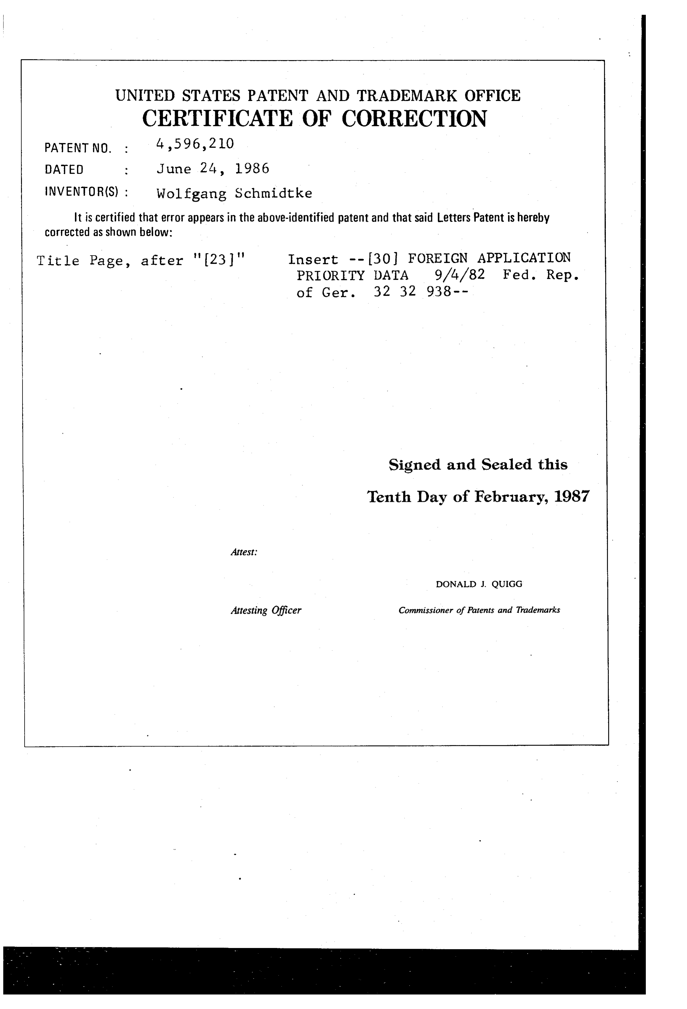
UNITED STATES PATENT AND TRADEMARK OFFICE
CERTIFICATE OF CORRECTION
INVENTOR(S) : Wolfgang Schmidtke
It is certified that error appears in the above-identified patent and that said Letters Patent is hereby Corrected as shown below:
Title Page, after '23)" Insert -- 30 FOREIGN APPLICATION PRIORITY DATA 9/4/82 Fed. Rep.
Signed and Sealed this
Tenth Day of February, 1987
Attest
DONALD J. QUIGG
Attesting Officer Commissioner of Patents and Trademarks
Provenance
- Collection
- Cited prior art
- Original PDF
- patentimages.storage.googleapis.com →
- Filed
- 1983-08-31
- Pages
- 9
- Method
- pdftotext (the PDF's own text layer) + pdftoppm 300dpi page scans
- Source
- Google Patents bibliographic record
- Granted
- 1986-06-24
- Inventors
- Wolfgang Schmidtke; KOHLENSAUREWERKE C G ROMMENHOLLER GmbH
- Transcribed from
- patentimages.storage.googleapis.com →