patent · US3933606
Water treatment process and apparatus
20 January 1976
Page 1 — bibliographic record
United States Patent (19) 11 3,933,606 Harms (45) Jan. 20, 1976 (54) WATER TREATMENT PROCESS AND Primary Examiner-John H. Mack APPARATUS Assistant Examiner-A. C. Prescott Attorney, Agent, or Firm-Lyon and Lyon 75) Inventor: Harry Keith Harms, Woodland
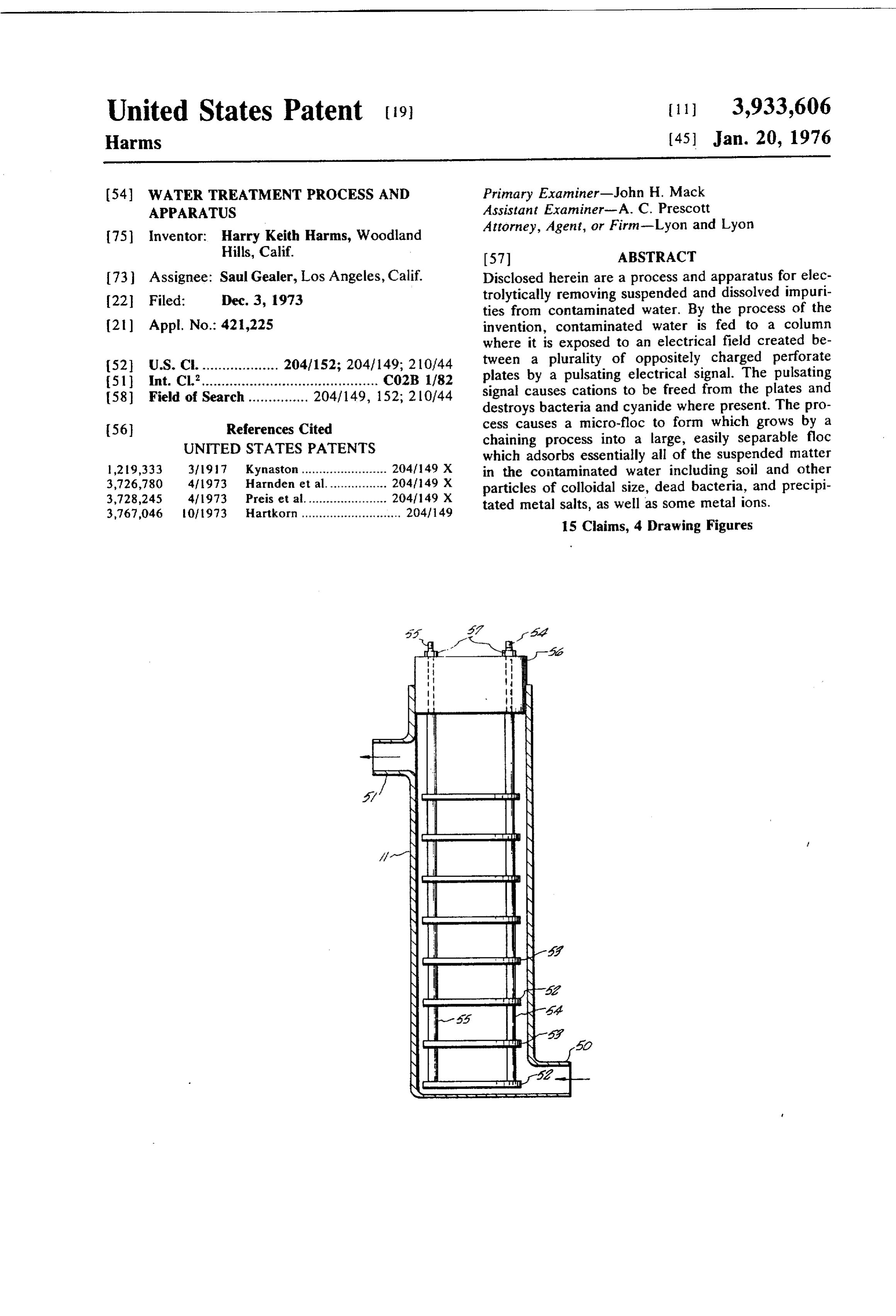
Hills, Calif. 57 ABSTRACT 73 Assignee: Saul Gealer, Los Angeles, Calif. Disclosed herein are a process and apparatus for elec 22 Filed: Dec. 3, 1973 trolytically removing suspended and dissolved impuri ties from contaminated water. By the process of the (21) Appl. No.: 421,225 invention, contaminated water is fed to a column where it is exposed to an electrical field created be 52 U.S. C. ................... 204/152; 204/149; 210/44 tween a plurality of oppositely charged perforate (51 int. Cl'............................................ CO2B 1/82 plates by a pulsating electrical signal. The pulsating 58) Field of Search............... 204/149, 152; 210/44 signal causes cations to be freed from the plates and destroys bacteria and cyanide where present. The pro 56 References Cited cess causes a micro-floc to form which grows by a
UNITED STATES PATENTS
chaining process into a large, easily separable floc which adsorbs essentially all of the suspended matter 1,219,333 3/97 Kynaston........................ 204/149 X in the contaminated water including soil and other 3,726,780 4f1973 Harnden et al................. 204749 X particles of colloidal size, dead bacteria, and precipi 3,728,245 4/1973 Preis et al...................... 204/149 X tated metal salts, as well as some metal ions. 3,767,046 0.1973 Hartkorn............................ 204/149 15 Claims, 4 Drawing Figures
Page 2
Drawing sheet — no readable text.
Page 3
Drawing sheet — no readable text.
Page 4
Drawing sheet — no readable text.
Page 5
SUMMARY OF THE INVENTION
WATER TREATMENT PROCESS AND APPARATUS
In its most general sense, the apparatus of the inven
BACKGROUND OF THE INVENTION tion comprises an upright column with a water inlet port adjacent its lower end and a water outlet port
This invention relates to the field of fluid purifica 5 adjacent its upper end, the column containing a plural tion, and in particular, to the electrolytic treatment of ity of perforate contaminated water. There are many known methods essentially perpendicular plates disposed in the column in a plane of treating contaminated water to remove varying de thereof. In some embodiments to the longitudinal axis of the invention, the grees of contamination therefrom. The two most com treating apparatus consists of a plurality of identical mon methods of water purification are chemical pre columns arranged in series. The traverse dimensions of cipitation and reverse osmosis. It has been known to the plates approximate the inside dimensions of the electrolytically treat polluted water to remove contami column to insure that, in operation, essentially all of the nants therefrom. For example, Landreth in U.S. Pat, contaminated water entering the column passes No. 1,131,067 describes a liquid treatment process in 15 through the perforations in the plates. The transverse which contaminated liquid is fed through a treating dimension of individual perforations is preferably not chamber containing multiple electrodes spaced and greater than about 7% of the diameter of the plates. insulated from each other and so disposed that the The perforations are preferably approximately evenly liquid passes in a zigzag direction backwardly and for spaced across the plates, most preferably in such num wardly through the chamber between the electrodes. 20 ber as to comprise from about 20% to about 80% of the The electrodes are alternately charged and are supplied area of the plates. The plates are disposed in two sets with an electric current of unspecified nature from a comprised of alternating anode and cathode plates. A generator. Similarly, U.S. Pat. No. 744, 171 to Davis, et source of a variable pulsating electrical signal is pro al discloses a method for separating oil and similar 25 vided to simultaneously supply the individual plates of impurities from water by subjecting the solution to an each set with pulsating electrical signals of opposite electrolytic field of unspecified nature produced by signs. It is understood that the particular width, cross iron electrodes which may be arranged so that the are sectional shape and spacing of the plates in the column water flows past them in a zigzag manner. According to matters not critical except as discussed above, these being Davis, et al, the oil combines with iron freed from the 30 The platesof design choice.
electrodes to form a separable scum. More recently, ductive may be fabricated from a variety of con materials.
Vellas, et al in U.S. Pat. No, 3, 192,142 have proposed anode be comprised The primary requirement is that the to pass contaminated water through a multiple elec metal such as aluminum predominately of a floc forming or iron. In one embodiment, trode coagulation set so designed that the polluted both the anode and cathode plates are fabricated from water circulates parallel to electrodes supplied with a 35 iron so even wear of the plates may be effected by rectified pulsating electrical current. According to the reversing the sign of the signal applied to the set of patentees, this step has the effect of starting a process plates. In another embodiment, the cathode plates may of coagulation, The oppositely charged electrodes are be fabricated from a non-gassing material such as mo disclosed as fabricated from different materials, prefer lybdenum.
ably rustless steel and aluminum and the current to the 40 For each contaminated water source being used, electrodes is selected to transmit positively charged there is an optimum current density on the plates to ions to the solution. So far as I am aware, none of the affect the desired contaminant removal. In practical methods described above have proved adaptable to operation, this means that for each contaminated water large-scale treatment of contaminated water. source, there is an optimum current which should be Other workers have commented on the importance supplied to the column since the plates will usually be of zeta potential in floc formation. See Thomas M. of a fixed size. Since changes in conductivity of the Riddick Chemical Engineering, June 26, 1961, pages contaminated water may occur, which would reduce or 121-126 and July 10, 1961, pages 141-146. Briefly, increase the current at a constant voltage, it is desirable that the variable pulsating electrical signal source be zeta potential is a measure of the electro-kinetic charge 50 designed that surrounds suspended particulate matter. Riddick applied to with the the capability of varying the voltage column in inverse relation to the conduc describes the charges on raw water turbidity as pre tivity to maintain a constant current. As a practical dominately electro-negative and strong enough to cause significant mutual repulsion of the suspended matter, pulsating electrical signal supply units with a fixed A.C. voltage supply are not capable of the range particles. When the zeta potential of suspended colloi. ss of dal matter is reduced to near zero, plus or minus about in voltage variations necessary to react to large changes conductivity of the contaminated water. Therefore, 5 millivolts, repulsive forces are eliminated, allowing in one embodiment the colloidal particles to collide with each other where provided for sensingofconductivity the invention, sensing means are and changes thereof upon the forces of adhesion, cohesion and mechanical of the contaminated water prior to its introduction to locking result in agglomeration, in turn occasioning 60 the column. The sensing means produces a signal which formation of a large particle size floc which readily causes a voltage controller to vary the input A.C. volt settles out of the solution. While Riddick controls Zeta age to the pulsating electrical signal supply unit thereby potential of colloidal matter by chemical means, appli allowing the unit to react to broad changes in conduc cant has found that the process and apparatus de tivity of the contaminated water source.
scribed herein apparently also has the effect of reduc- 65 The method of generating the variable pulsating elec ing the zeta potential on suspended colloidal matter so trical signal to be applied to the plates of the column is a floc can readily form which entraps virtually all of the not critical to the invention, the only requirement being suspended matter in the solution being treated, that the signal creates a pulsating electrical field be
Page 6
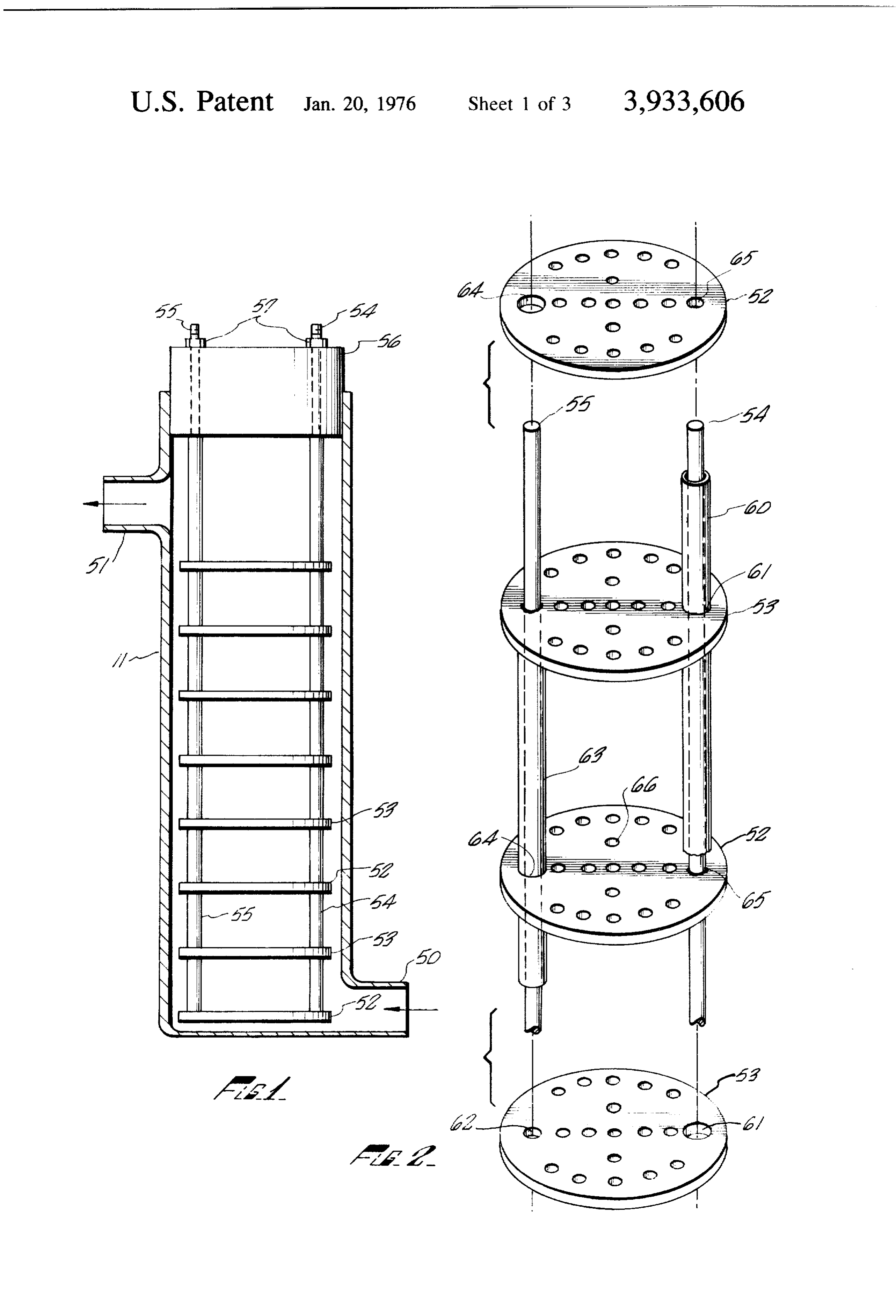
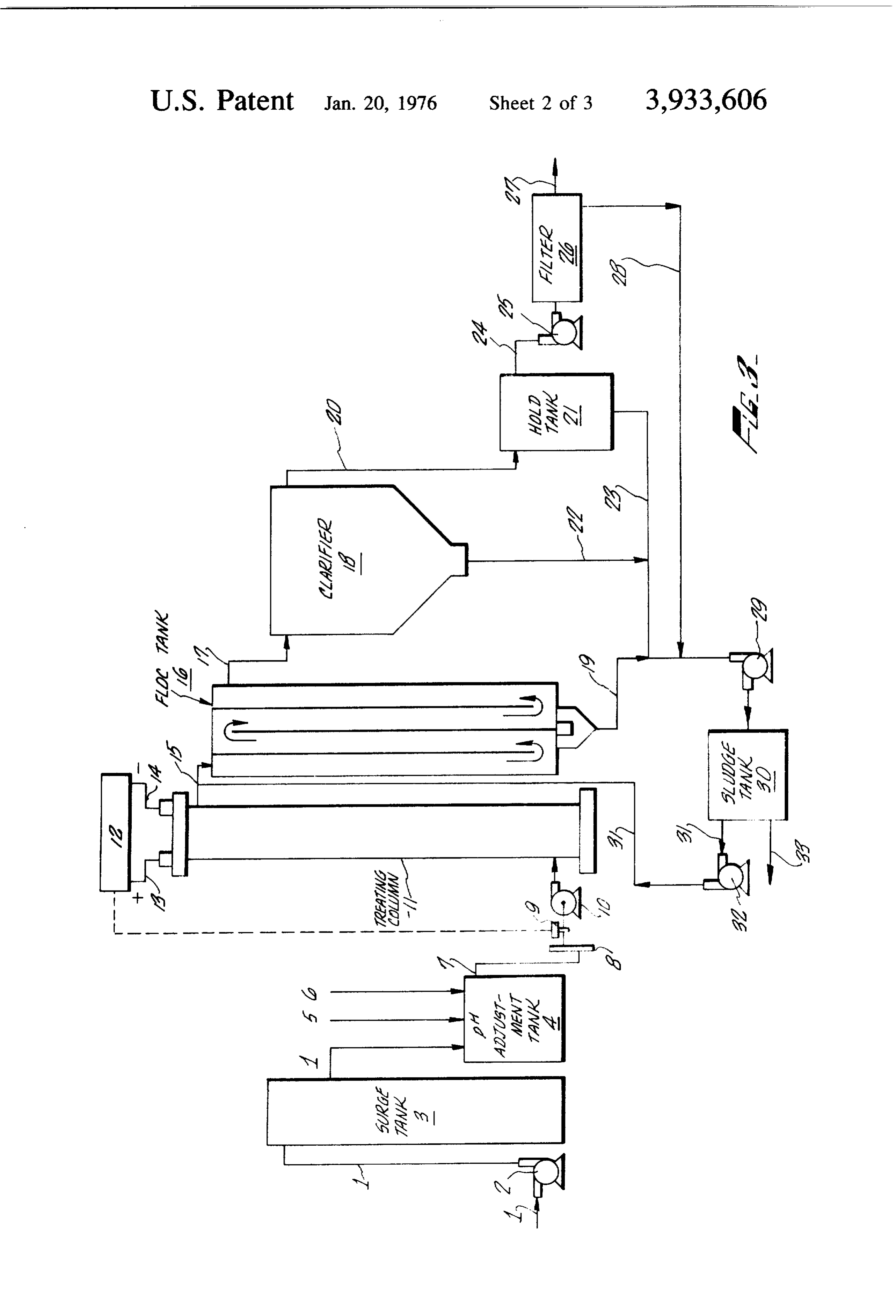
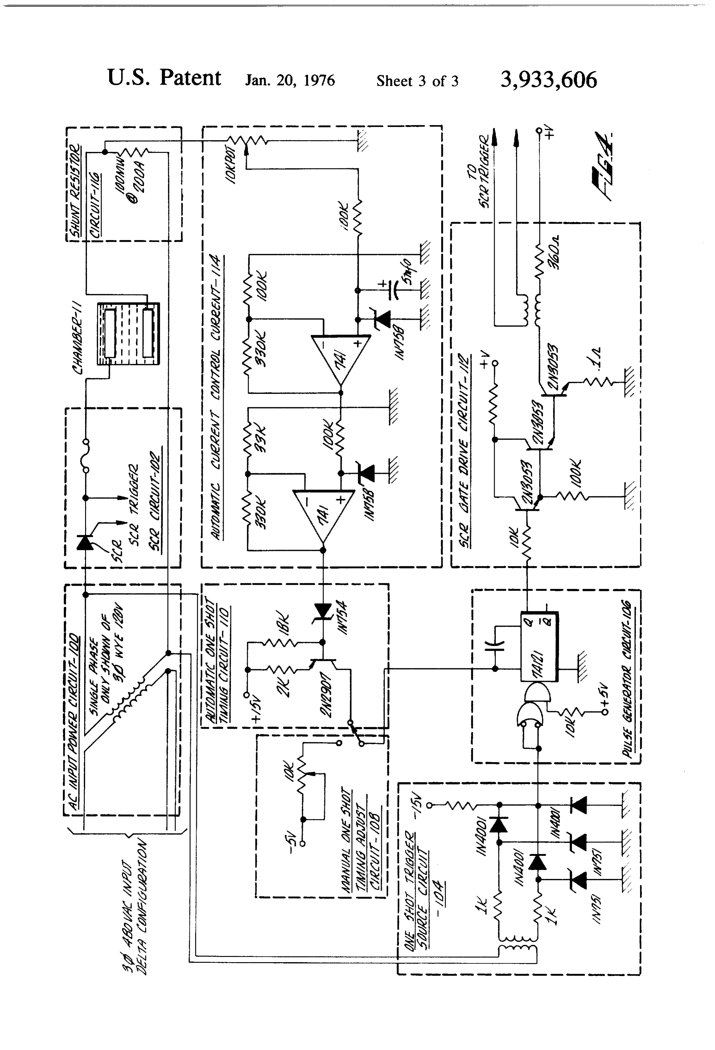
tween the plates. In some embodiments of the inven process of of the invention in its most general sense is tion, it is desirable that the signal develop an electrical complete. The following post-treatment process steps field near the plates on the order of magnitude of at serve only to aid floc formation and removal from the least about 10 - 10 volts/cm. Regardless of the man Water, ner the electrical signal is generated, it is economically 5. Post-treatment of the treated water begins by feeding desirable to apply the potential between the plates only it to a flocculation chamber of such capacity that the for that part of the wave form where the amplitude is average residence time of water therein is at least about relatively high since it is only at the higher amplitudes 20 minutes. In the flocculation chamber, micro-floc that the higher electrical fields are created. particles grow through a chaining process and absorb in one embodiment of the invention, the electrical from the solution metal ions as well as substantially all signal to the column is provided by a unit which con of the contained organic and inorganic solid particles, verts an electrical alternating potential by halfwave including dead bacteria, colloidal particles and newly rectification, to pulsating electrical signals of opposite precipitated metal salts. The floc is then removed by signs variable in magnitude and the point on the A.C. clarification and filtering apparatus to yield essentially cycle at which the potential is applied. In another em pure water and a sludge which may be further treated bodiment, the electrical signal to the apparatus of the to recover metals and other valuable by-products. invention is provided by a unit which converts an elec DESCRIPTION OF THE DRAWINGS trical alternating potential by full wave rectification, to pulsating electrical signals of opposite signs variable in FIG. is a partial cross-sectional view of one embodi magnitude and the point on the A.C. cycle at which the ment of the apparatus of the invention. potential is applied. The advantage of full wave rectifi FIG. 2 is a perspective view of a portion of the appa cation is that a higher frequency is obtained. The ratus of FIG. 1 showing the arrangement of the plates. higher frequency provides twice the number of pulses FIG. 3 is a schematic process flow diagram of one provided by half wave rectification for the same power embodiment of the process of the invention. usage and therefore improved efficiency is obtained. FIG. 4 is a simplified schematic block diagram of a In yet another embodiment, an electrical A.C. signal portion of an electrical circuit suitable for supplying a may first be rectified by a full wave bridge and then pulsating electrical signal to the apparatus of the inven filtered to provide a constant level D.C. voltage. The tion.
D.C. voltage may then be applied to a chopper-inverter DETALED DESCRIPTION OF THE INVENTION circuit which will provide a square wave, pulsed output that is infinitely variable in frequency and width. Such One embodiment of the apparatus of the invention is a circuit provides advantages over the previously depicted in FIG. 1 and comprises an upright column 11 described phase controlled methods in that the instan which may be constructed from any non-conductive taneous turn on and turn off characteristic of the material, e.g., lucite or glass. It is understood that the square wave form allows the potential to be applied only requirement for construction of column 11 is that only during the most efficient high amplitude portion of the interior of the column be non-conducting. Thus, the wave form. the materials of construction may include a column of By the process of this invention, contaminated water an outer conductive shell about a non-conductive lin containing any combination of organic and inorganic 4) ing. When the column is constructed of a transparent, suspended solids of whatever particle size, dissolved non-conductive material such as lucite or glass, the metal salts and cyanide is fed to the water treatment additional advantage of being able to observe its opera apparatus heretofore described. Preferably, the con tion accrues. Column 11 has water inlet port 50 and taminated water is pretreated prior to introduction into water outlet port 51. Disposed within the column in a the apparatus by adjusting its pH to a range of from plane essentially perpendicular to the longitudinal axis abut 8. () to about 10.0 by addition of an aqueous acid 45 thereof are a plurality of perforate plates 52 and 53. or base such as HCl or NaOH, as required, and by Plates 52 and 53 are fabricated from iron and are elec screening out gross particulate matter, as by passage trically insulated from the column. Their transverse through a relatively large screen, as for example, a dimensions approximate the inner diameter of the col screen of about 30 mesh. It is understood that the umn so as to insure that, in operation, essentially all of method and apparatus of the invention are operable the contaminated water being treated passes through over the entire pH range and that pH adjustment plate perforations.
merely functions to bring the hydroxide ion concentra In FIG. 1, numerals 52 and 53 designate two mutually tion to a level which present experience has demon alternating sets of plates disposed in the column. Cath strated provides the most economic contaminant re ode plates 52 are electrically connected to cathode 54 moval. and anode plates 53 are electrically connected to The contaminated water is then fed to the column anode 55. Anode 55 and cathode 54 are mounted in where it flows through the perforations in the plates column l l in any convenient manner as by being se and is exposed to the pulsating electrical signal Sup cured by nuts 57 to plug 56.
plied to the plates. The optimal average residence time 6) FIG. 2 more clearly depicts the arrangement of the between the oppositely charged plates of the apparatus plates. In operation, each alternating set of plates is may be readily determined for each source of contami supplied with a variable pulsating electrical signal of nated water being treated and depends on the degree opposite sign. In the embodiment of the invention de and type of contaminant removal desired. picted in FIG. 2, cathode plates 52 are supplied with The application of the pulsating electrical signal to 65 mounting perforations 64 and 65. The diameter of the plates as the contaminated water flows through the perforation 65 is approximately equal to the outside column causes metal salts to precipitate from the Solu diameter of cathode rod 54 so that plate 52 may be tion, bacteria to be killed, and cyanide to be destroyed. electrically connected to cathode rod 54 at the periph and initiates formation of micro floc. At this point, the ery of perforation 65. The diameter of perforation 64 is
Page 7
slightly larger than the outside diameter of insulator 63 by simplified block schematic diagram FIG. 4. FIG. 4 so that insulator 63 may be passed through plate 52 depicts in simplified form, one third of a circuit capable thereby electrically insulating it from anode rod 55. of providing a pulsating electrical signal to each of Anode plates 53 are provided with perforations 61 and three columns employed in series in the process of the 62. Perforation 62 is of a diameter approximately equal 5 invention. The circuitry is repeated three times to pro to the outside diameter of anode 55 so that plates 53 vide a signal to each unit. In this embodiment of unit may be electrically connected to anode rod 55 at the 12, input A.C. power circuit 100 is supplied with a 480 periphery of perforation 62. The diameter of perfora volt, three-phase electrical signal in delta configuration tion 61 is slightly larger than the outside diameter of () and the signal is transformered down to a 20 volt, insulator 60 so that insulator 60 may be passed through three-phase wye configuration. Each phase of the 120 plate 53, electrically insulating it from cathode 54. volt signal is applied to a silicon-controlled rectifier Plates 52 and 53 are provided with perforations 66 (SCR) in SCR circuit 102. The SCR is triggered by the through which the water being treated flows. control circuits 104-116 described below. When trig In one embodiment of the invention, as represented gered, the SCR applies an electrical signal to the plates in FIG. 2, plates 52 and 53 are identical 5% inch diame of the column. The timing of the triggering signal deter ter iron plates with 4 inch diameter perforations set on mines the portion of the halfwave rectified wave form a % inch staggered center which total about 40% of the applied.
area of the plates. In other embodiments of the inven The triggering circuit comprises one shot trigger tion, as for example when non-gassing cathode plates 20 source circuit 104 which maintains syncronization be are employed, the cathode plates would be provided tween SCR triggering and the input A.C. voltage. The with minimum number of relatively large holes while signal developed by one shot trigger source circuit 104 the anode plates will have a maximum amount of small is supplied to pulse generator 106 which develops a holes to increase the ratio of anode area to cathode variable time based square wave pulse. Pulse timing area thereby increasing the current density on the an may be adjusted either by manual one shot timing ad ode. just circuit 108 or by automatic one shot timing circuit Cathode rod 54 and anode rod 55 are supplied with 1 10, if automatic mode is desired. The line adjusted pulsating electrical signals of opposite signs by variable pulse developed by pulse generator 106 is applied to pulsating electrical signal unit generating means 12. As SCR gate drive circuit 112 which applies the triggering was pointed out above, in some embodiments of the signal to activate the SCR in SCR circuit 102. The invention, it is desirable that the pulse provided by unit 30 current across the plates of column 11 is maintained at 12 develops electrical fields at the surface of the anode constant level by shunt resistor circuit 16 which plate on the order of magnitude of at least 10 - 10 supplies a signal to automatic current control circuit volts/cm. This is desirable because it has been calcu 14 which automatically adjusts the pulse width lated that when a potential is applied between spaced thereby maintaining the current to chamber 11 at a iron plates through a conductive solution, space charge 35 constant value. In one embodiment unit 12 may be sheaths will be produced at the surface of the plates. supplied with an A.C. voltage control regulator, not The space charge sheaths are exceedingly thin com shown, which adjusts the A.C. voltage supply in incre pared to separation of the electrodes. For example, ments responsive to the conductivity of the contami with a normal separation of electrodes in a sodium 4) nated water so that the current control feature of unit chloride solution, as for example, one inch or more, the 12 may function over a broad conductivity range. space charge sheaths at a potential of 100 volts and a The process of one embodiment of the invention is current of 1 amp or any combination totaling 100 volt depicted in schematic form in FIG. 3. Contaminated amps will be 0.376 x 10-cm in thickness. The high water 1 is pumped by pump 2 to surge tank 3. The electrical fields of 10-0 volts/cm magnitude referred 45 contaminated water may contain as contaminants to be to above are developed in these space charge sheaths. removed from the solution, organic and inorganic sus The configuration of the apparatus of the invention pended solids, dissolved metal salts such as iron, lead, insures that substantially all of the contaminated water tin, nickel, cobalt, cadmium, chromium, zinc, alumi being treated is exposed to these high-potential space num, magnesium, calcium, sodium, copper, mercury, charge sheaths. For convenience, the calculated poten 50 silver, gold, platinum, and antimony salts as well as tial assumed planar plates. When the irregularity of the cyanide complexes of these and other metals. From iron surface and the edge of the perforations are taken surge tank 3, contaminated water 1 flows to pH adjust into account, it is probable that the potential may be an ment tank 4. If the pH of the contaminated water 1 is order of magnitude higher at some points. The calcu outside the range of from about 8.0 to about 10.0, the lated potential is sufficient to remove metal ions from pH is adjusted to within that range by the addition of an the surface of the anodes into the contaminated water, 55 aqueous acid 5, as for example, HCl or HSO, or an cause disassociation of cyanide molecules and water, aqueous base 6, as for example, sodium or calcium and destroy bacteria in a sodium chloride solution, It is hydroxide as required.
understood that the magnitude of the electrical charge The contaminated water 7 whose pH has been ad in the space charge sheath necessary to affect a desired 60 justed to within the specified range is screened through degree of contaminate removal will vary with the com screen filter 8 which is comprised of a screen of rela position of the water being treated. tively large mesh, as for example, about 30 mesh or The apparatus of the invention includes means to larger. The conductivity of contaminated water 7 is supply the sets of plates 52 and 53 with a variable pull measured by conductivity sensor 9 which produces a sating electrical signal of opposite signs. This means is signal from which a voltage controller adjusts the A.C. generally designated as unit 12 in the process flow 65 voltage supply to pulsating electrical signal unit 12 so diagram of FIG. 3. In the embodiment of the invention that the unit may regulate the electrical signal supplied where the signal is supplied by halfwave rectification as to the plates of the treating apparatus ill as described described above, the circuitry of unit 12 is as depicted above. The contaminat d water 7 is then pumped by
Page 8
pump 10 to the water inlet port at the bottom of col clarifier. Clarified water 20 is fed to holding tank 21 umn 1 1. The water passes through the plates of column and the floc and sludge 22 is removed from the bottom 11 and is exposed to a pulsating electrical signal sup of the clarifier and treated as described below. Addi plied to the plates by unit 12 via electrical leads 13 and tional sludge and floc 23 will settle to the bottom of 14. The electrical signal destroys bacteria in the water, hold tank 2 and is removed and treated as described destroys cyanide, disassociates water to form hydroxide ions, and releases iron cations from the iron anode below. The treated water 24 from hold tank 21 is plates. It is believed that iron cations form compounds pumped by pump 25 through polish filter 26 which may such as Fe(HO)(OH), "", etc. which polymerize be any suitable commercially available polish filter and initiate the formation of a floc. In addition, the iron capable of removing the floc particles which have not cations replace metal cations above iron in the electro been removed from the water. Essentially pure, treated motive series in the solution, causing the precipitation of metal salts from the water. Insoluble metal hydrox water moved 27 from which all floc particles have been re emerges from filter 26 and may be used as de ides are also formed as precipitates. Flox formation sired. The filter cake 28 is removed from filter 26, begins almost instantaneously in the form of a micro 15 floc which becomes visible as chaining occurs as the combined with floc and sludge 19, 22. and 23 and contaminated water passes through the plates of col pumped by pump 29 to sludge tank 30. If desired, the umn 11. overflow 31 from sludge tank 30 may be returned to For each water source being treated, there is an opti the floc tank by pump 32. The concentrated sludge 33 mum current density on the plates, which will vary 20 may be treated as desired, e.g., to recover metals there depending on the contaminants sought to be removed from, or may be disposed of.
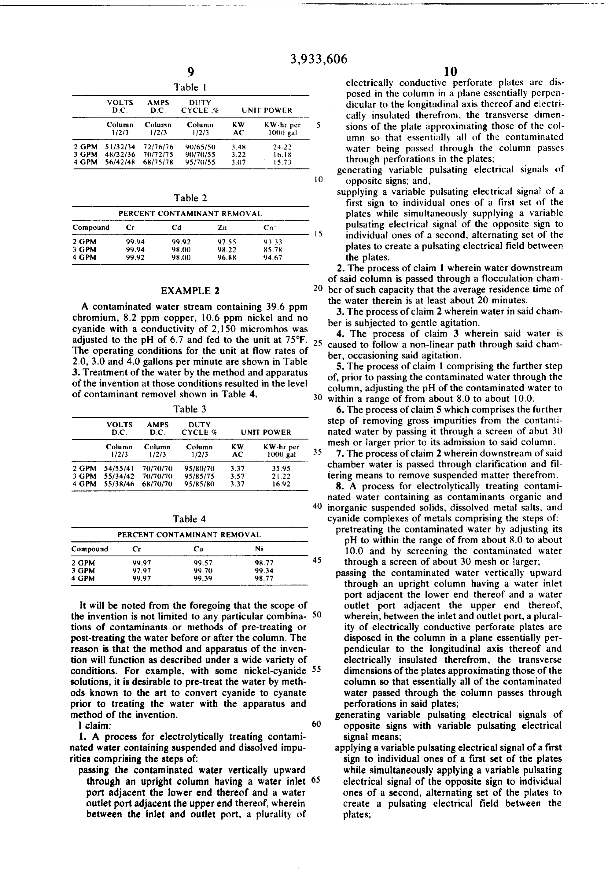
from the solution. This optimum current density can The apparatus and method of the invention are fur readily be determined for a particular solution merely ther disclosed and described by the following examples by varying the current supplied to the plates of the in which they are employed to treat the waste stream apparatus or a pilot version thereof to achieve optimum from a metal plating plant. The treating process was removal of desired contaminants. The column is sized so as to economically process any desired flow rate. In essentially as described in FIG. 3 except that three operation, the total current supplied to the apparatus is identical columns were connected in series and no automatically maintained at a constant by electrical clarifier was employed. The circuitry of unit 12 was signal unit 12 as described above. The treatment time, 30 essentially as described in FIG. 4. Each of the three i.e., the residence time of the water in column 11 will circuits, only one of which is depicted in FIG. 4 was vary with each contaminated water source being used to develop a half wave rectified pulsating electri treated according to the nature and quantity of the cal signal to be applied to the plates of each of the three contaminants sought to be removed.
The treated water 15 next flows to flocculation tank 35 columns.
wave form
The duty cycle, that is, the portion of the over which the signal is applied to the col 16 which is of such size as to provide a residence time umn, is variable from 0 - 100%. As will be noted from of the treated water in the tank of at least about 20 minutes. As the water passes through tank 16, it may be the tables below, in some instances the voltage and caused to follow a non-linear path through the tank as duty cycle applied to each column was varied from by the Wier design depicted in FIG. 3. The Wier design 40 column to column, since the temperature rise through maintains the water in gentle agitation which aids in each column increases the conductivity of the contami floc formation and growth. It is also believed that the nated water thus requiring a lower voltage and duty column design of tank 16 aids in floc formation due to cycle in each succeeding column. The voltage and amp the pressures present at the bottom of the column. figures for each columnn are average figures across the During this time, the micro-floc grows through chain 45 plates of the column and the power consumption inn ing into large floc particles which absorb metals from kilowatt hours per 1,000 gallons is the total power the solution as well as substantially all of the solids in consumption of the columns. The three columns em the treated water, including colloidal suspended solids, dead bacteria and newly precipitated metals. It is be from ployed had a 6-inch inside diameter and a flow height lieved that one reason the floc is able to absorb the 50 inlet 50 to outlet 51 of 78 inches. Each column colloidal particles is that subjecting the suspended had 28 identical iron plates 52 and 53 spaced 3 inches solids to the pulsating electrical signal in the treating apart and 5% inches in diameter. The plates contained apparatus reduces the zeta potential of the normally 4 inch diameter perforations set on a 2 inch staggered negatively charged colloidal particles to near neutral center totaling about 40% of the area of the plates. ity, reducing the repulsive forces between the colloidal 55 EXAMPLE 1 particles and allowing them to collide with each other whereupon the forces of adhesion, cohesion, and me A contaminated water stream containing 19.2 ppm chanical locking result in agglomeration of the particles chromium, 25.0 ppm cadmium, and 22.5 ppm zinc in a and absorption thereof by the growing floc. solution containing 45.0 ppm CN (colormetric titra Treated water 17 containing suspended floc is re 60 moved from floc tank 16 and fed to clarifier 18. Some tion for free cyanide) and having a conductivity of of the floc will settle in the floc tank and is removed 2,225 micromhos was adjusted to a pH of 8.0 and fed to from the bottom as sludge 19 which is handled as de the unit at 75F. The operating conditions for the unit scribed below. Clarifier 18 is designed to aid in removal at flow rates of 2, 3, and 4 gallons per minute are shown of the floc particles. In a preferred design, the clarifier 65 in Table 1. Treatment of the water by the method and may be shaped to function like a cyclone and remove apparatus of the invention at these conditions resulted most of the suspended floc. Alternatively, the clarifier in the level of contaminant removal shown in Table 2. may be a centrifuge or other commercially available
Page 9
Table electrically conductive perforate plates are dis posed in the column in a plane essentially perpen
WOLTS
AMPS
DUTY
CYCLE . N POWER dicular to the longitudinal axis thereof and electri cally insulated therefrom, the transverse dimen
Column Cublumn
Column
KW-hr per
5 sions of the plate approximating those of the col umn so that essentially all of the contaminated
water being passed through the column passes 4 GPM 5614248 68/75/78 95/7/55 3.7 573 through perforations in the plates, generating variable pulsating electrical signals of
O opposite signs, and,
Table 2 supplying a variable pulsating electrical signal of a first sign to individual ones of a first set of the
PERCENT CONTAMENANT REMOVA plates while simultaneously supplying a variable Compound Cr Cd An iC pulsating electrical signal of the opposite sign to 2 GPM 99.94 99.92 97.55 93.33 5 individual ones of a second, alternating set of the 3 GPM 99.94 98.0 98.22 85.78 plates to create a pulsating electrical field between 4 GPM 99.92 98.) 96.88 94.6 the plates.
2. The process of claim 1 wherein water downstream of said column is passed through a flocculation cham
EXAMPLE 2 20 ber of such capacity that the average residence time of
A contaminated water stream containing 39.6 ppm the3. water therein is at least about 20 minutes. chromium, 8.2 ppm copper, 0.6 ppm nickel and no ber is subjected toof gentle The process claim 2 wherein water in said cham agitation.
cyanide with a conductivity of 2,150 micromhos was adjusted to the pH of 6.7 and fed to the unit at 75°F. 25 caused to follow a non-linear3path 4. The process of claim wherein said water is
The operating conditions for the unit at flow rates of ber, occasioning said agitation. through said cham 2.0, 3.0 and 4.0 gallons per minute are shown in Table 3. Treatment of the water by the method and apparatus of,5.prior The process of claim 1 comprising the further step to passing the contaminated water through the of the invention at those conditions resulted in the level of contaminant removel shown in Table 4. column, adjusting the pH of the contaminated water to 30 within a range of from about 8.0 to about 10.0.
Table 3 6. The process of claim 5 which comprises the further WOLTS AMPS DUTY step of removing gross impurities from the contami D.C. D.C. CYCLE UN POWER nated water by passing it through a screen of abut 30 Column Column Column KW KW-hr per mesh or larger prior to its admission to said column. f213 2/3 11213 AC 2000 gal 7. The process of claim 2 wherein downstream of said 2 GPM 54/55/41 70/70/70 95/8(170 3.37 35.95 chamber water is passed through clarification and fil 3 GPM SS134/42 (f7f7) 95/85,75 3.57 2.22 tering means to remove suspended matter therefrom. 4 GPM 55138146 68/70/7) 95/85/80 3.37 92 8. A process for electrolytically treating contami nated water containing as contaminants organic and 40 inorganic suspended solids, dissolved metal salts, and
Table 4 cyanide complexes of metals comprising the steps of:
PERCENT CONTAMINANT REMOVAL pretreating the contaminated water by adjusting its
pH to within the range of from about 8.0 to about 10.0 and by screening the contaminated water 2 GPM 99.9 99.57 98.77 45 through a screen of about 30 mesh or larger; 3GPM 97.97 99.7) 99.34 passing the contaminated water vertically upward
through an upright column having a water inlet port adjacent the lower end thereof and a water
It will be noted from the foregoing that the scope of outlet port adjacent the upper end thereof, the invention is not limited to any particular combina 50 wherein, between the inlet and outlet port, a plural tions of contaminants or methods of pre-treating or ity of electrically conductive perforate plates are post-treating the water before or after the column. The disposed in the column in a plane essentially per reason is that the method and apparatus of the inven pendicular to the longitudinal axis thereof and tion will function as described under a wide variety of 55 electrically insulated therefrom, the transverse conditions. For example, with some nickel-cyanide dimensions of the plates approximating those of the solutions, it is desirable to pre-treat the water by meth column so that essentially all of the contaminated ods known to the art to convert cyanide to cyanate water passed through the column passes through prior to treating the water with the apparatus and perforations in said plates; method of the invention. generating variable pulsating electrical signals of | claim: 60 opposite signs with variable pulsating electrical 1. A process for electrolytically treating contami signal means;
nated water containing suspended and dissolved impu applying a variable pulsating electrical signal of a first rities comprising the steps of: sign to individual ones of a first set of the plates passing the contaminated water vertically upward while simultaneously applying a variable pulsating through an upright column having a water inlet 65 electrical signal of the opposite sign to individual port adjacent the lower end thereof and a water ones of a second, alternating set of the plates to outlet port adjacent the upper end thereof, wherein create a pulsating electrical field between the between the inlet and outlet port, a plurality of plates,
Page 10
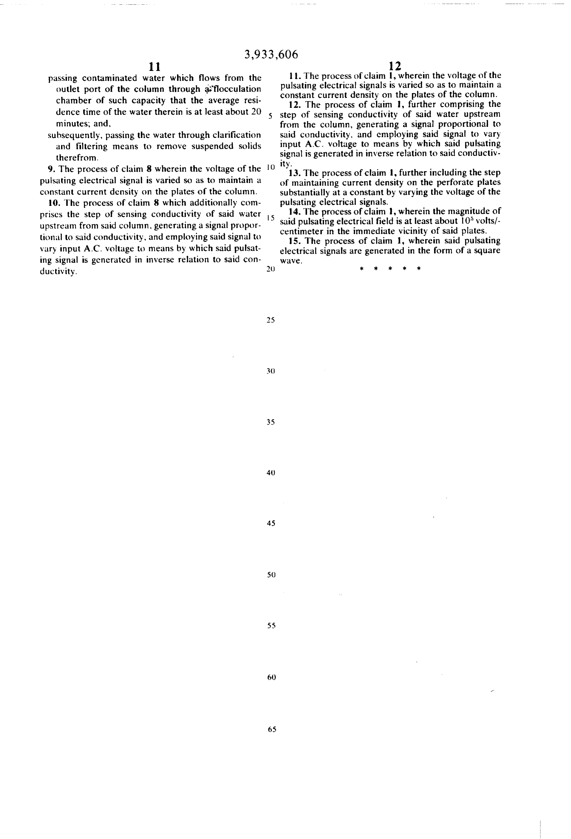
passing contaminated water which flows from the ll. The process of claim 1, wherein the voltage of the outlet port of the column through aflocculation constantpulsating electrical signals is varied so as to maintain a chamber of such capacity that the average resi current density on the plates of the column. 12. The process of claim 1, further comprising the dence time of the water therein is at least about 20 5 step of sensing conductivity of said water upstream minutes, and, from the column, generating a signal proportional to subsequently, passing the water through clarification said conductivity, and cmploying said signal to vary and filtering means to remove suspended solids input A.C. voltage to means by which said pulsating therefrom. signal is generated in inverse relation to said conductiv 9. The process of claim 8 wherein the voltage of the ity.13. The process of claim 1, further including the step
pulsating electrical signal is varied so as to maintain a of maintaining current density on the perforate plates constant current density on the plates of the column. substantially at a constant by varying the voltage of the 10. The process of claim 8 which additionally com pulsating electrical signals.
prises the step of sensing conductivity of said water 5 14. The process of claim , wherein the magnitude of said pulsating electrical field is at least about 10 volts/- upstream from said column, generating a signal propor centimeter tional to said conductivity, and employing said signal to in the immediate vicinity of said plates. 15. The process of claim 1, wherein said pulsating vary input A.C. voltage to means by which said pulsat electrical signals are generated in the form of a square ing signal is generated in inverse relation to said con WW2.
ductivity. k sk ck k xk
Provenance
- Collection
- Cited prior art
- Original PDF
- patentimages.storage.googleapis.com →
- Filed
- 1973-12-03
- Pages
- 10
- Method
- pdftotext (the PDF's own text layer) + pdftoppm 300dpi page scans
- Source
- Google Patents bibliographic record
- Granted
- 1976-01-20
- Inventors
- Harry Keith Harms
- Transcribed from
- patentimages.storage.googleapis.com →