patent · US5575860
Fiber optic power-generation system
19 November 1996
Page 1 — bibliographic record
HIIIHIIIHIII
United States Patent (19) 11 Patent Number: 5,575,860 Cherney 45) Date of Patent: Nov. 19,9 1996
(54 FIBER OPTIC POWER-GENERATION 4,242,147 12/1980 DeToia .................................... 136/253 SYSTEM 4,529,830 7/1985 Daniel ..................................... 136/246 5,089,055 2/1992 Nakamura ............................... 136,248 76 Inventor: Matthew Cherney, One Park La.,
Mount Vernon, N.Y. 10552 FOREIGN PATENT DOCUMENTS
61-189673 8/1986 Japan ..................................... 136/246 (21) Appl. No. 374,308 4-111475 4/1992 Japan ..................................... 136/246 22 Filed: Jan. 18, 1995 OTHER PUBLICATIONS J. I. Davis, "Solar Cell R & D', Space/Aeronautics, Apr.
Related U.S. Application Data 1959, pp. 44–46.
63) Continuation-in-part of Ser. No. 289.285, Aug. 11, 1994, Primary Examiner-Aaron Weisstuch Pat. No. 5,501,743. Attorney, Agent, or Firm-Herbert Dubno 51 Int. Cl. - - - - - - - - - - - - - - - - - - - - H01L 31/045; HOlL 31/052; (57) ABSTRACT
52) U.S. Cl. ........................... 136/245; 136/246; 136/248 A fiber optical solar power generating system provides a 58 Field of Search ..................................... 136,245,246, tower outside a structure to be supplied with solar energy 36/248 and on which a multiplicity of collectors is provided. An optical fiber trunk carries the collected optical energy to the 56 References Cited structure in which a photovoltaic and/or a light/heat trans ducing stack can be provided and to which light is distrib
4,068,121 1/1978 Bringhurst et al................. 250227.28 not occupy large areas of the property. 4,140,142 2/1979 Dormidontov et al. . ....... 136/246 4,153,475 5/1979 Hider et al.............................. 136/246 10 Claims, 10 Drawing Sheets
STRUCTURE. SPACE HEATNG
ELECTRICAL
POWER - DEWAR
LIGHT 1 HEAT
Page 2
Drawing sheet — no readable text.
Page 3
Drawing sheet — no readable text.
Page 4
Drawing sheet — no readable text.
Page 5
Drawing sheet — no readable text.
Page 6
Drawing sheet — no readable text.
Page 7
Drawing sheet — no readable text.
Page 8
Drawing sheet — no readable text.
Page 9
Drawing sheet — no readable text.
Page 10
Drawing sheet — no readable text.
Page 11
Drawing sheet — no readable text.
Page 12
FIBER OPTIC POWER-GENERATION with the light energy being transmitted to them by distributor SYSTEM plates forming part of the stack and juxtaposed with the photovoltaic or photothermal plates, the light energy being
CROSS REFERENCE TO RELATED delivered to the distributors by optical fibers. APPLICATION Preferably the light is collected by an external tower This application is a continuation-in-part of Ser. No. structure supplied with a multiplicity of collectors, espe cially lenses or lens systems from which the optical energy 08/289.285 filed Aug. 11, 1994, now U.S. Pat. No. 5,501, is delivered to the building via an optical fiber trunk which 743. terminates at one or both of the stacks described.
FIELD OF THE INVENTION
10 More particularly, a fiber optic power-generating system can comprise:
The present invention relates to a fiber optic power a tower positioned outside a structure to be supplied with generating system and more particularly to an improved power, alternative energy source for structures utilizing optical fiber a multiplicity of solar-light collectors on the tower over at energy transmission. 15 least part of a height of the tower and around a periphery thereof;
BACKGROUND OF THE INVENTION respective optical fibers assigned to the collectors and transmitting light therefrom, the optical fibers being formed
Increasing concern with fossil fuel as an energy source into an optical fiber trunk extending from the tower into the and concern with the safety of nuclear power has led to 20 structure; and interest in the development of alternative energy sources within the structure a stack of energy transducing plates such as solar power. each receiving at least one optical fiber from the trunk and One of the major problems with solar power is the large provided with means for distributing light delivered by an area required for photovoltaic converters and even thermal optical fiber over the respective plate for producing energy solar energy converters when these must be directly posi 25 utilized at least in part within the structure. tioned in the path of the solar radiation. The invention also is a fiber optic system which com Furthermore, efforts to overcome this problem by the use prises:
of light concentrators or the like have not always proved to a stack of photovoltaic plates; be effective. Reference may be had, for example, to U.S. Pat. respective light distributors juxtaposed with each of the No. 5,195,503 which discloses a relatively complex system 30 intended to maximize the solar collection of heat from the plates, the light distributors being sandwiched between pairs sun with automatic tracking of the path of the sun. of photovoltaic plates of the stack; and Efforts have also been made to increase the energy output respective light-delivering optical fibers connected to by passing a compressed gas through a solar collector (U.S. 35 each of the light distributors for supplying light thereto. Pat. No. 4.942,736) or to provide tower systems which It will be apparent that the stacking arrangement of the convey a vapor to a high point at which the vapor is photovoltaic panels allows for a high panel surface area and condensed to a liquid and the falling liquid will drive a therefore high electrical productivity in a small volume. turbine (see U.S. Pat. No. 4,757,687). Other solar collectors Since the stack is contained in the structure or building, of interest are described in U.S. Pat. Nos. 4,117,682, 4,236, 40 the photovoltaic panels are not exposed to weather or 937, 4,676,068, 4.558,551, 4,392,008, 4,219,729, 4,720, 170 physical stress and therefore can be fabricated at lower cost. and 3,996,918, The fiber optic main cable can be branched to distribute the These systems do not solve the main problems discussed light to the mirror lined panel stacks and can receive the light above with respect to the large areas required, the complex from relatively inexpensive sources like mirrors or lenses. ity of the systems, and the ability to install an effective solar 45 The fact that such mirrors or lenses can be distributed, e.g. energy system in, for example, a residence or similar struc on the tower or at each collector can eliminate potential ture. problems with overheating. When built to scale, the fiberop tic cables may be as wide as (and similar to) polyacrylate
OBJECTS OF THE INVENTION curtain rods. The stacks may be moved closer to the collec tors so that the fiberoptic distance is minimal, with metal
It is, therefore, the principal object of the present inven 50 wire covering the remaining distance to the main structure.
tion to provide an improved solar energy collection and According to a feature of the invention, the plates can be utilization system whereby drawbacks of earlier systems are electrically connected in series and tied to a storage system, avoided, the spacial requirements are greatly reduced and e.g. one or more batteries, which, in turn, supply an inverter the portion of the apparatus which must be contained in the structure to be supplied with the energy is extremely con 55 for producing alternating current for the building or to a capacitance-regulation system. The means for distributing pact.
the light can be brush plates of optical fiber bristles or
Another object of the invention is to provide a low-cost light-conductive plates (e.g. of a polyacrylate) provided with high-efficiency system which is not limited by the need to diffuse surfaces facing the respective photovoltaic plates. cover large areas of the property with solar collectors or The collectors may have a mushroom shape upon which photovoltaic sheets and which nevertheless can generate arrays of lenses are provided and the mushroom-shaped useable electrical energy and heat at high efficiency. collectors may themselves be stackable by having the stem SUMMARY OF THE INVENTION of one collector fit into the convex body of another. Hex agonal convex lenses in the shape of a honeycomb make an
I have discovered that these objects are readily attainable, 65 efficient collection system.
utilizing either photovoltaic (semiconductor) plates or pho I have found, moreover, that the principle of utilizing a tothermal transducers, by providing the transducers in stacks stack of photovoltaic members so as to provide them in a
Page 13
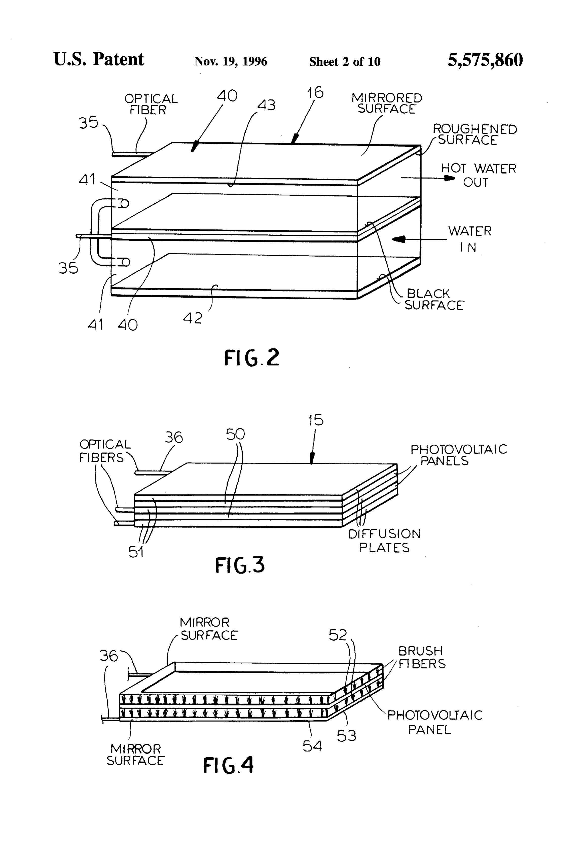
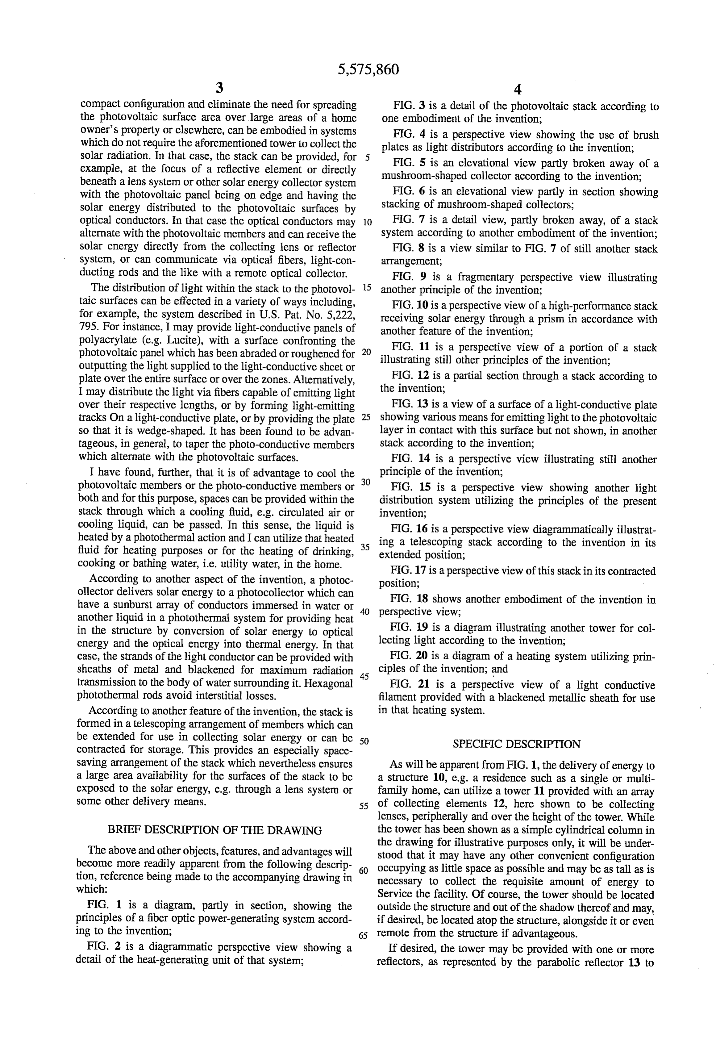
compact configuration and eliminate the need for spreading FIG. 3 is a detail of the photovoltaic stack according to the photovoltaic surface area over large areas of a home one embodiment of the invention;
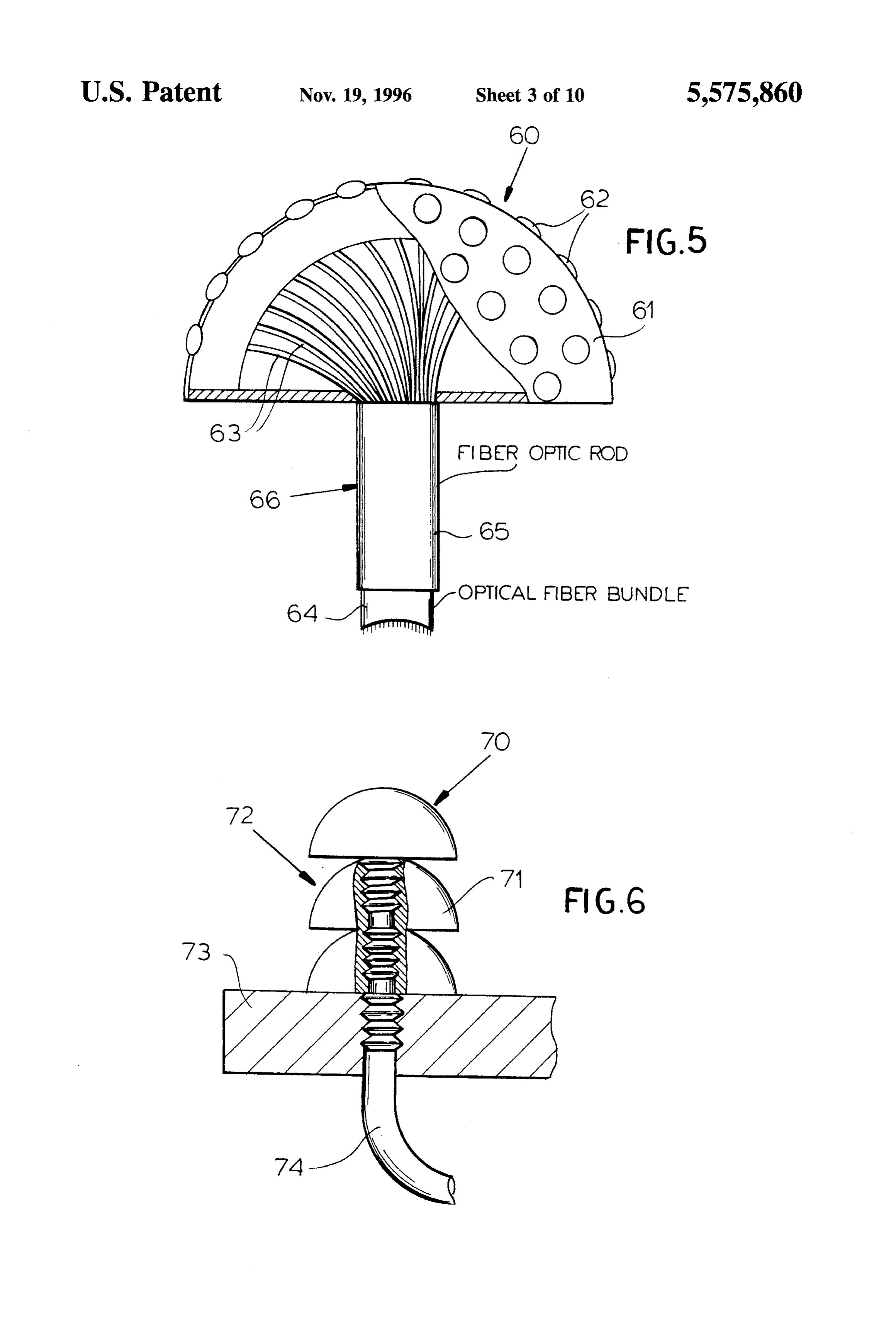
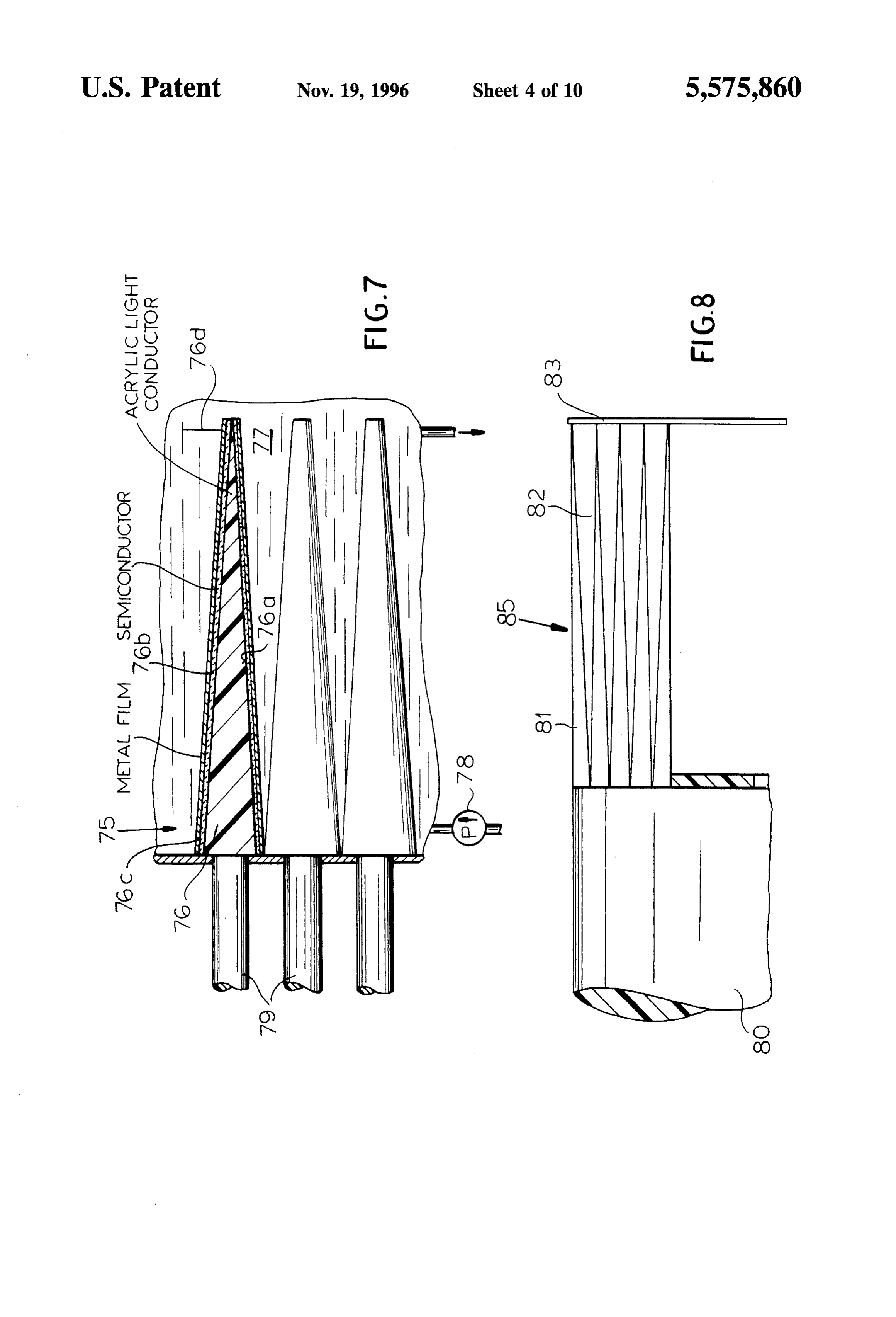
owner's property or elsewhere, can be embodied in systems FIG. 4 is a perspective view showing the use of brush which do not require the aforementioned tower to collect the plates as light distributors according to the invention; solar radiation. In that case, the stack can be provided, for FIG. 5 is an elevational view partly broken away of a example, at the focus of a reflective element or directly mushroom-shaped collector according to the invention; beneath a lens system or other solar energy collector system with the photovoltaic panel being on edge and having the FIG. 6 is an elevational view partly in section showing solar energy distributed to the photovoltaic surfaces by stacking of mushroom-shaped collectors; optical conductors. In that case the optical conductors may 10 FIG. 7 is a detail view, partly broken away, of a stack alternate with the photovoltaic members and can receive the system according to another embodiment of the invention; solar energy directly from the collecting lens or reflector FIG. 8 is a view similar to FIG. 7 of still another stack system, or can communicate via optical fibers, light-con arrangement;
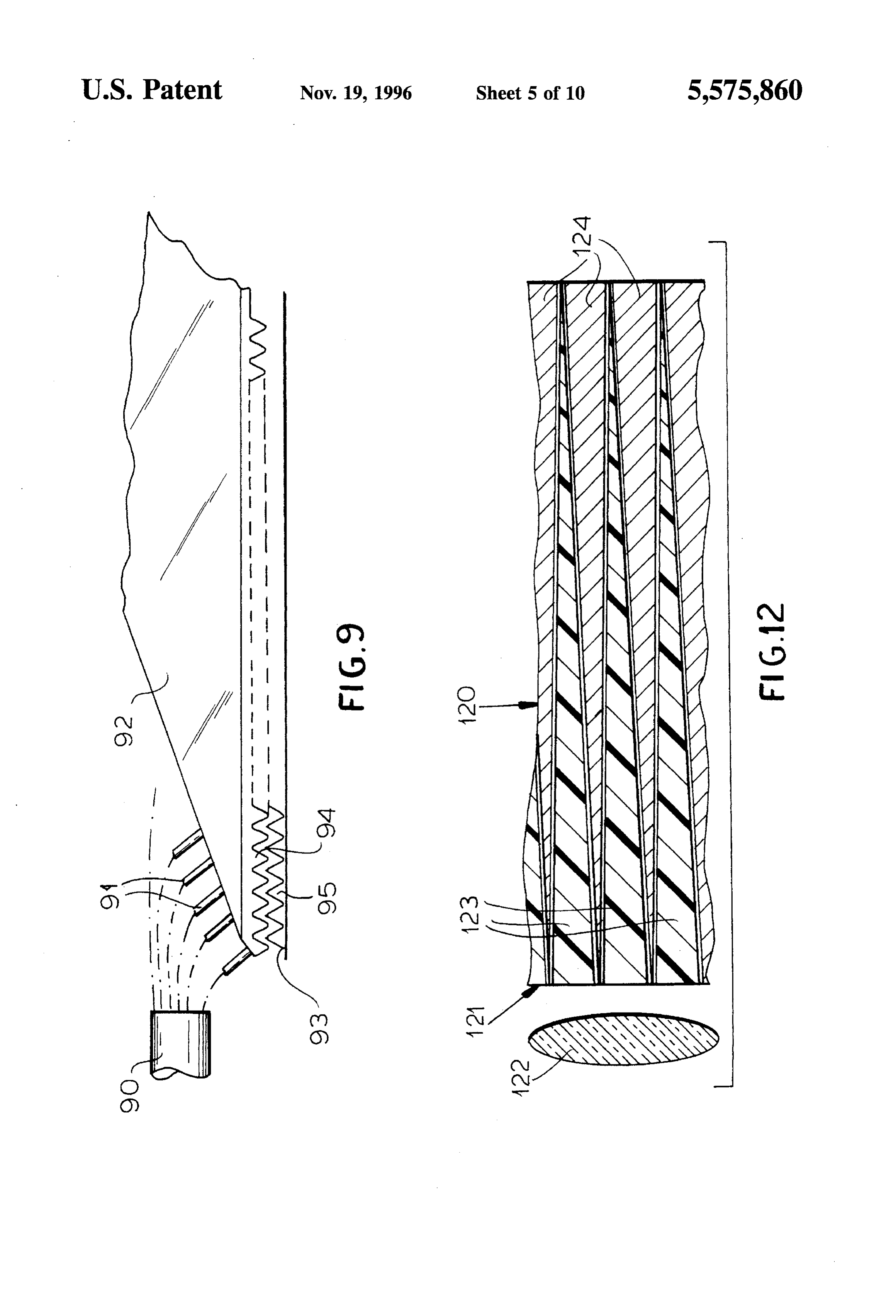
ducting rods and the like with a remote optical collector. FIG. 9 is a fragmentary perspective view illustrating The distribution of light within the stack to the photovol 15 another principle of the invention;
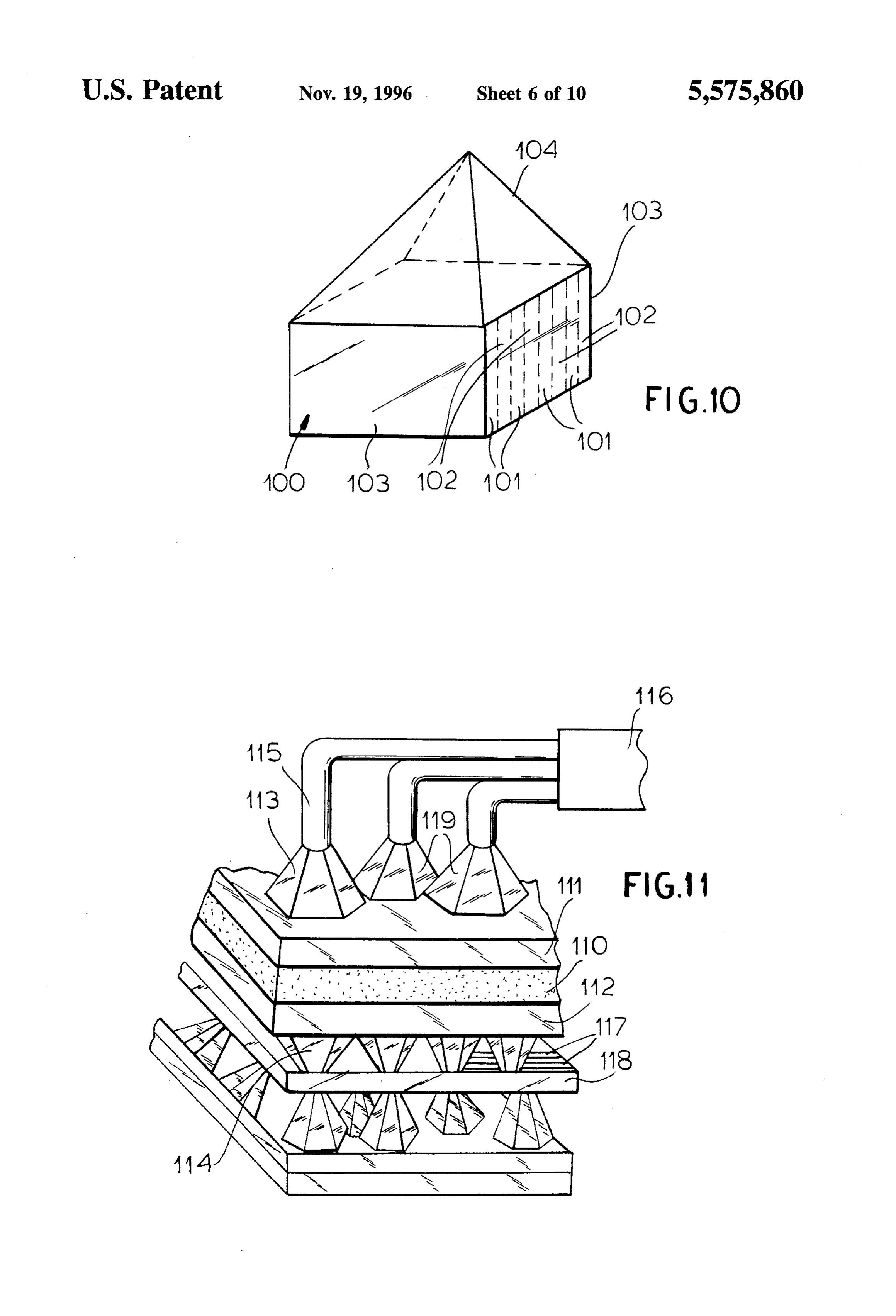
taic surfaces can be effected in a variety of ways including, FIG. 10 is a perspective view of a high-performance stack for example, the system described in U.S. Pat. No. 5,222, receiving solar energy through a prism in accordance with 795. For instance, I may provide light-conductive panels of another feature of the invention;
polyacrylate (e.g. Lucite), with a surface confronting the FIG. 11 is a perspective view of a portion of a stack photovoltaic panel which has been abraded or roughened for 20 illustrating still other principles of the invention; outputting the light supplied to the light-conductive sheet or plate over the entire surface or over the zones. Alternatively, FIG. 12 is a partial section through a stack according to I may distribute the light via fibers capable of emitting light the invention;
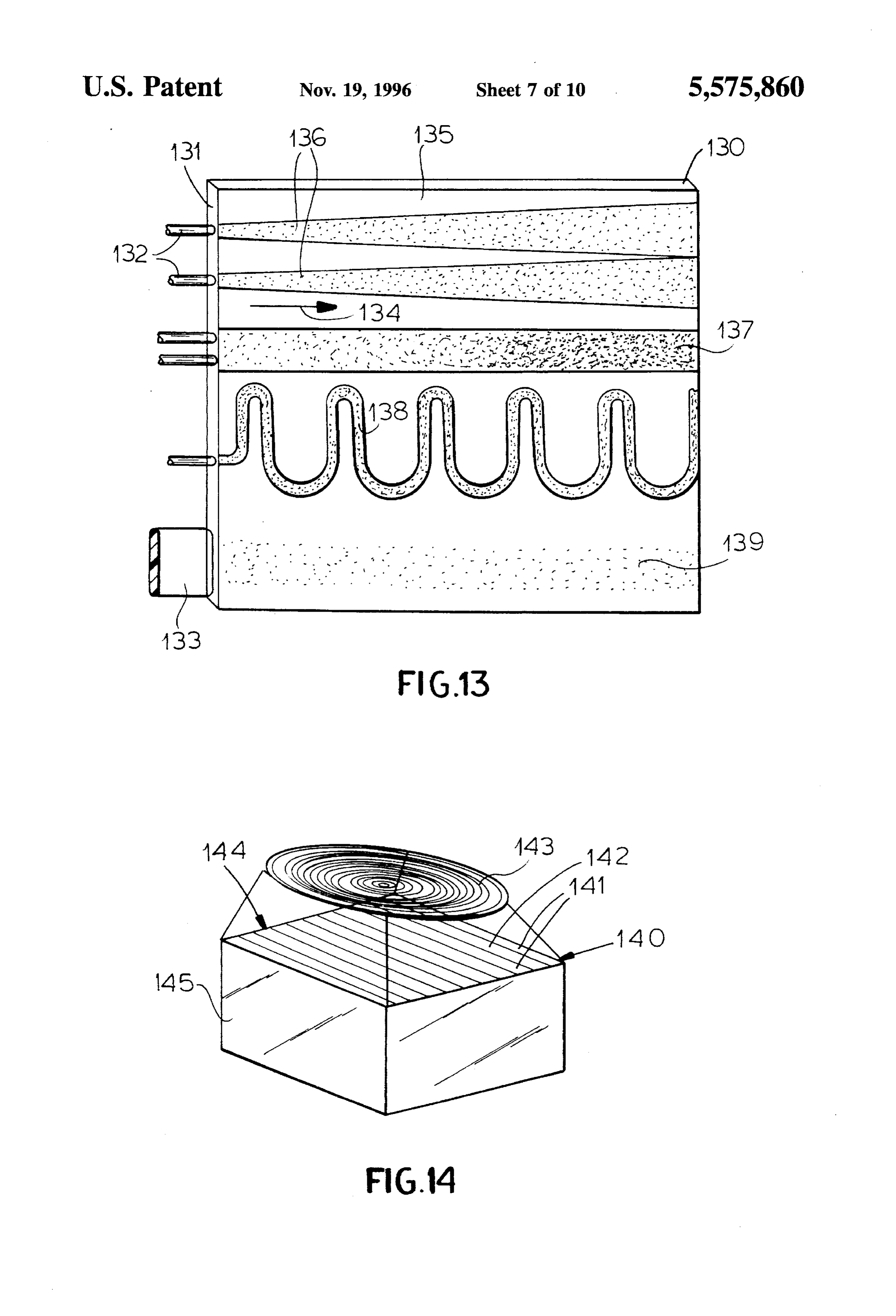
over their respective lengths, or by forming light-emitting FIG. 13 is a view of a surface of a light-conductive plate tracks On a light-conductive plate, or by providing the plate 25 showing various means for emitting light to the photovoltaic so that it is wedge-shaped. It has been found to be advan layer in contact with this surface but not shown, in another tageous, in general, to taper the photo-conductive members stack according to the invention; which alternate with the photovoltaic surfaces. FIG. 14 is a perspective view illustrating still another I have found, further, that it is of advantage to cool the 30 principle of the invention;
photovoltaic members or the photo-conductive members or FIG. 15 is a perspective view showing another light both and for this purpose, spaces can be provided within the distribution system utilizing the principles of the present stack through which a cooling fluid, e.g. circulated air or invention;
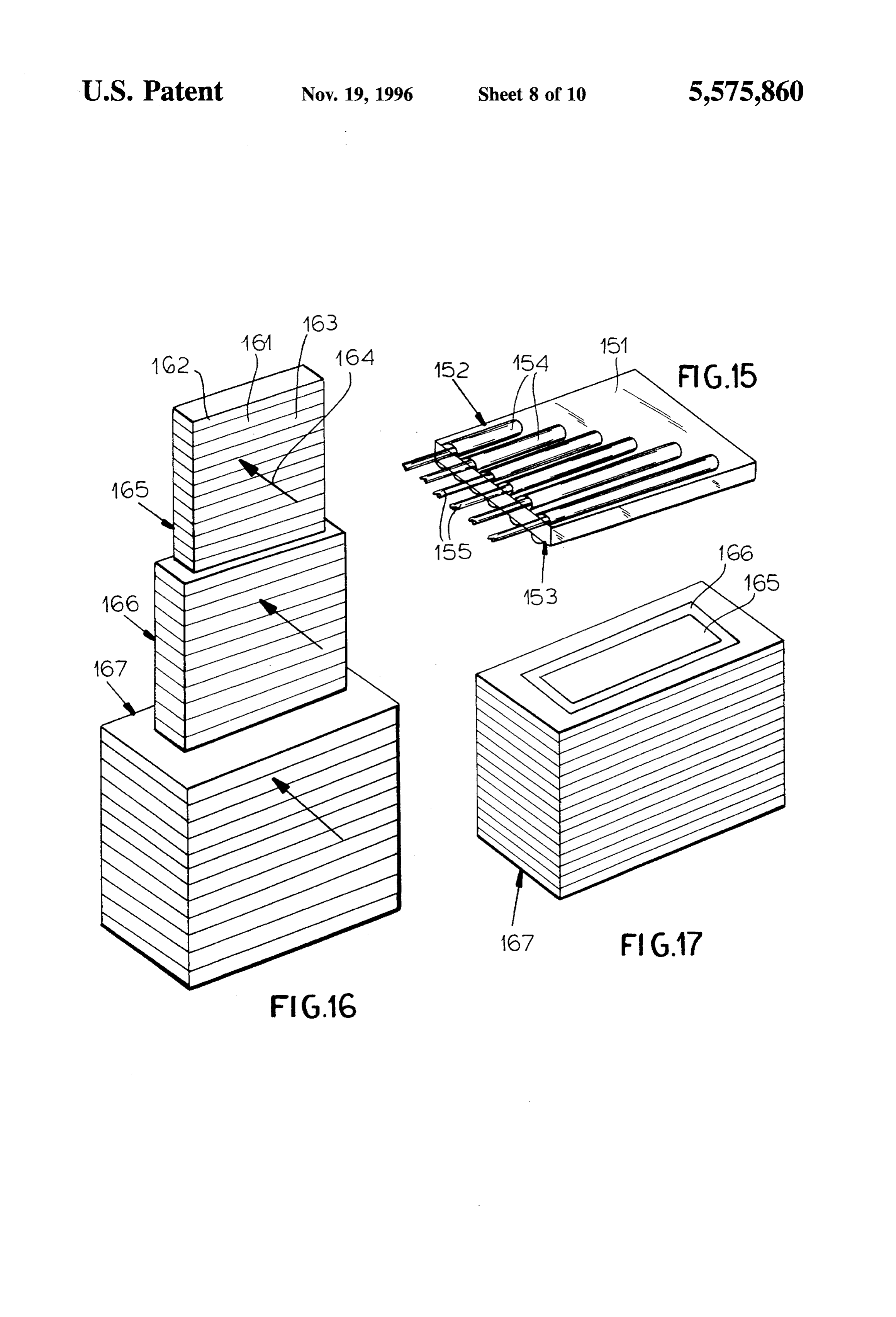
cooling liquid, can be passed. In this sense, the liquid is FIG. 16 is a perspective view diagrammatically illustrat heated by a photothermal action and I can utilize that heated 35 ing a telescoping stack according to the invention in its fluid for heating purposes or for the heating of drinking, extended position;
cooking or bathing water, i.e. utility water, in the home. FIG. 17 is a perspective view of this stackin its contracted According to another aspect of the invention, a photoc position;
ollector delivers solar energy to a photocollector which can FIG. 18 shows another embodiment of the invention in have a sunburst array of conductors immersed in water or 40 perspective view;
another liquid in a photothermal system for providing heat in the structure by conversion of solar energy to optical FIG. 19 is a diagram illustrating another tower for col energy and the optical energy into thermal energy. In that lecting light according to the invention; case, the strands of the light conductor can be provided with FIG. 20 is a diagram of a heating system utilizing prin sheaths of metal and blackened for maximum radiation ciples of the invention; and transmission to the body of water surrounding it. Hexagonal 45 FIG. 21 is a perspective view of a light conductive photothermal rods avoid interstitial losses. filament provided with a blackened metallic sheath for use According to another feature of the invention, the stack is in that heating system.
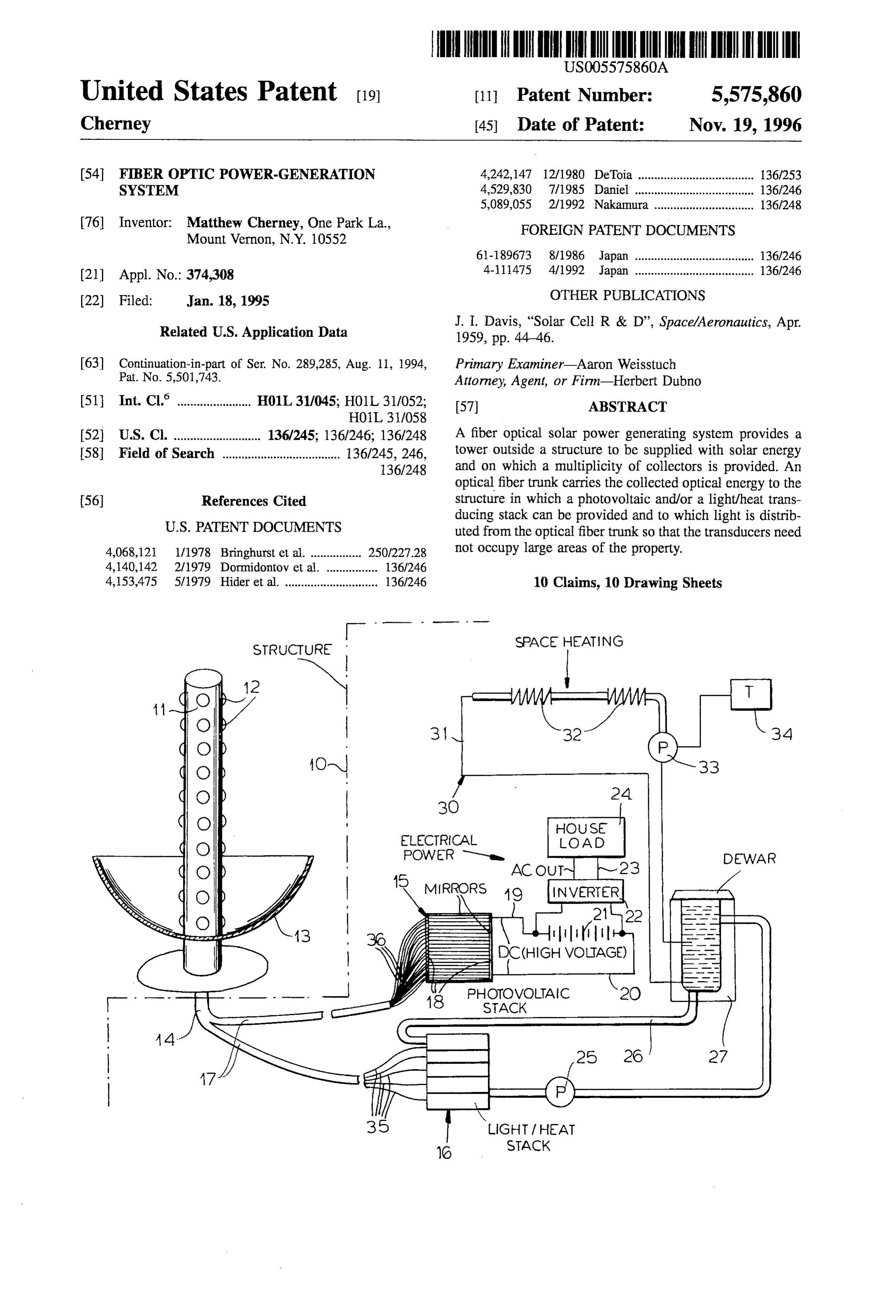
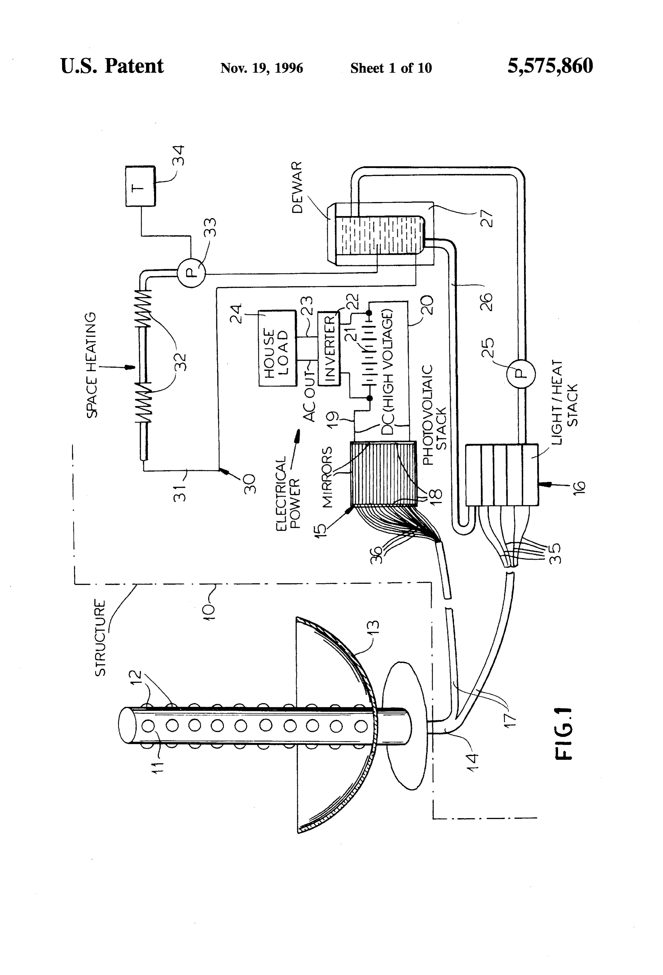
formed in a telescoping arrangement of members which can be extended for use in collecting solar energy or can be 50 SPECIFIC DESCRIPTION contracted for storage. This provides an especially space saving arrangement of the stack which nevertheless ensures As will be apparent from FIG. 1, the delivery of energy to a large area availability for the surfaces of the stack to be a structure 10, e.g. a residence such as a single or multi exposed to the solar energy, e.g. through a lens system or family home, can utilize a tower 11 provided with an array some other delivery means. 55 of collecting elements 12, here shown to be collecting lenses, peripherally and over the height of the tower. While
BRIEF DESCRIPTION OF THE DRAWING the tower has been shown as a simple cylindrical column in the drawing for illustrative purposes only, it will be under
The above and other objects, features, and advantages will stood that it may have any other convenient configuration become more readily apparent from the following descrip 60 occupying as little space as possible and may be as tall as is tion, reference being made to the accompanying drawing in necessary to collect the requisite amount of energy to which:
Service the facility. Of course, the tower should be located
FIG. 1 is a diagram, partly in section, showing the outside the structure and out of the shadow thereof and may, principles of a fiber optic power-generating system accord if desired, be located atop the structure, alongside it or even ing to the invention; 65 remote from the structure if advantageous. FIG. 2 is a diagrammatic perspective view showing a If desired, the tower may be provided with one or more detail of the heat-generating unit of that system; reflectors, as represented by the parabolic reflector 13 to
Page 14
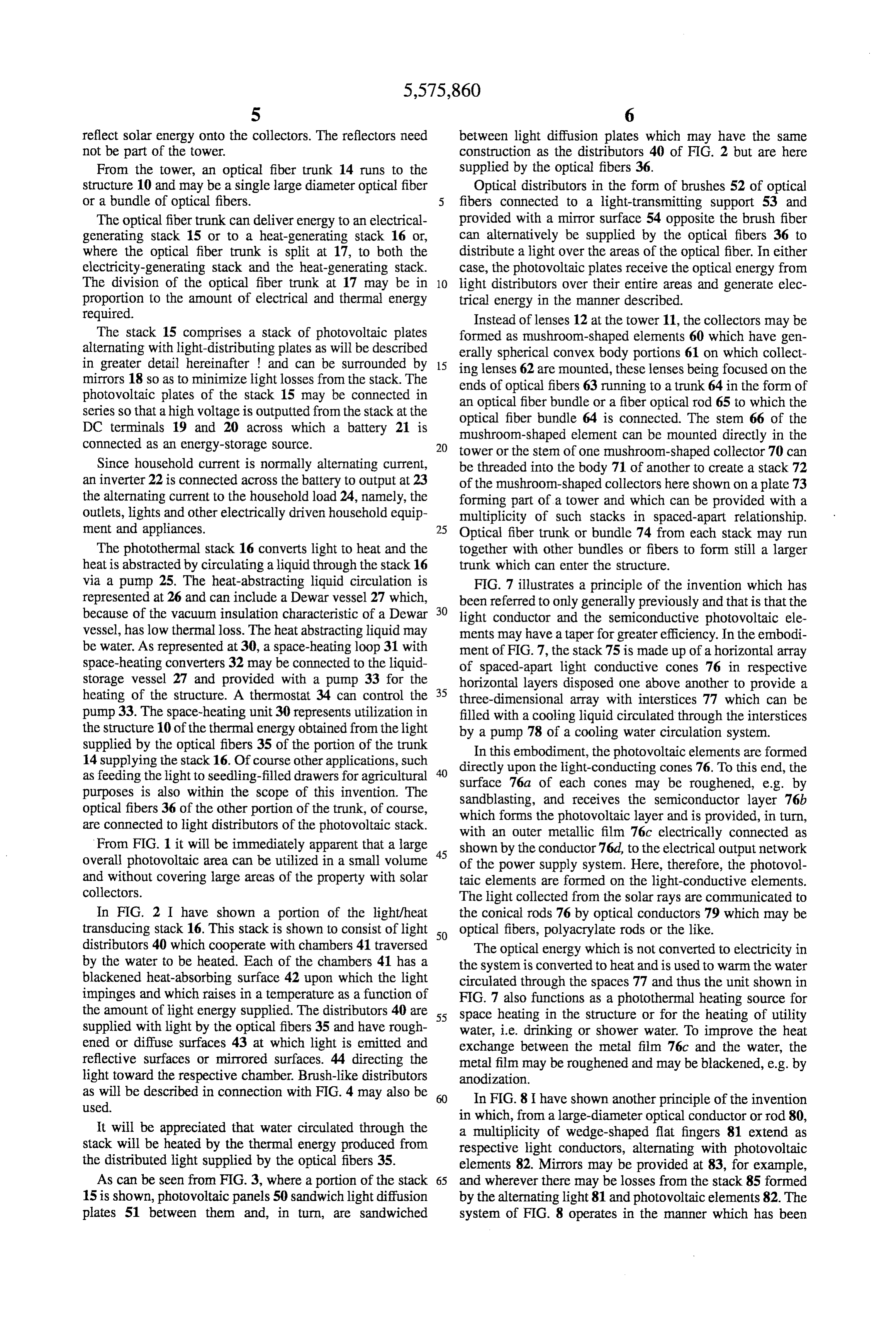
reflect solar energy onto the collectors. The reflectors need between light diffusion plates which may have the same not be part of the tower. construction as the distributors 40 of FIG. 2 but are here From the tower, an optical fiber trunk 14 runs to the supplied by the optical fibers 36.
structure 10 and may be a single large diameter optical fiber Optical distributors in the form of brushes 52 of optical or a bundle of optical fibers. fibers connected to a light-transmitting support 53 and The optical fibertrunk can deliver energy to an electrical provided with a mirror surface 54 opposite the brush fiber generating stack 15 or to a heat-generating stack 16 or, can alternatively be supplied by the optical fibers 36 to where the optical fiber trunk is split at 17, to both the distribute a light over the areas of the optical fiber. In either electricity-generating stack and the heat-generating stack. case, the photovoltaic plates receive the optical energy from The division of the optical fiber trunk at 17 may be in 10 light distributors over their entire areas and generate elec proportion to the amount of electrical and thermal energy trical energy in the manner described. required. Instead of lenses 12 at the tower 11, the collectors may be The stack 15 comprises a stack of photovoltaic plates formed as mushroom-shaped elements 60 which have gen alternating with light-distributing plates as will be described erally spherical convex body portions 61 on which collect in greater detail hereinafter and can be surrounded by 15 ing lenses 62 are mounted, these lenses being focused on the mirrors 18 so as to minimize light losses from the stack. The ends of optical fibers 63 running to a trunk 64 in the form of photovoltaic plates of the stack 15 may be connected in an optical fiber bundle or a fiber optical rod 65 to which the series so that a high voltage is outputted from the stack at the optical fiber bundle 64 is connected. The stem 66 of the DC terminals 19 and 20 across which a battery 21 is mushroom-shaped element can be mounted directly in the connected as an energy-storage source. 20 tower or the stem of one mushroom-shaped collector 70 can Since household current is normally alternating current, be threaded into the body 71 of another to create a stack 72 an inverter 22 is connected across the battery to output at 23 of the mushroom-shaped collectors here shown on a plate 73 the alternating current to the household load 24, namely, the forming part of a tower and which can be provided with a outlets, lights and other electrically driven household equip multiplicity of such stacks in spaced-apart relationship. ment and appliances. 25 Optical fiber trunk or bundle 74 from each stack may run The photothermal stack 16 converts light to heat and the together with other bundles or fibers to form still a larger heat is abstracted by circulating a liquid through the stack 16 trunk which can enter the structure. via a pump 25. The heat-abstracting liquid circulation is FIG. 7 illustrates a principle of the invention which has represented at 26 and can include a Dewar vessel 27 which, been referred to only generally previously and that is that the because of the vacuum insulation characteristic of a Dewar 30 light conductor and the semiconductive photovoltaic ele vessel, has low thermal loss. The heat abstracting liquid may ments may have a taper for greater efficiency. In the embodi be water. As represented at 30, a space-heating loop 31 with ment of FIG. 7, the stack 75 is made up of a horizontal array space-heating converters 32 may be connected to the liquid of spaced-apart light conductive cones 76 in respective storage vessel 27 and provided with a pump 33 for the horizontal layers disposed one above another to provide a heating of the structure. A thermostat 34 can control the 35 three-dimensional array with interstices 77 which can be pump 33. The space-heating unit 30 represents utilization in filled with a cooling liquid circulated through the interstices the structure 10 of the thermal energy obtained from the light by a pump 78 of a cooling water circulation system. supplied by the optical fibers 35 of the portion of the trunk In this embodiment, the photovoltaic elements are formed 14 supplying the stack 16. Of course other applications, such directly upon the light-conducting cones 76. To this end, the as feeding the light to seedling-filled drawers for agricultural surface 76a of each cones may be roughened, e.g. by purposes is also within the scope of this invention. The sandblasting, and receives the semiconductor layer 76b optical fibers 36 of the other portion of the trunk, of course, which forms the photovoltaic layer and is provided, in turn, are connected to light distributors of the photovoltaic stack. with an outer metallic film 76c electrically connected as From FIG. 1 it will be immediately apparent that a large shown by the conductor 76d, to the electrical output network overall photovoltaic area can be utilized in a small volume 45 of the power supply system. Here, therefore, the photovol and without covering large areas of the property with solar taic elements are formed on the light-conductive elements. collectors. The light collected from the solar rays are communicated to In FIG. 2 I have shown a portion of the light/heat the conical rods 76 by optical conductors 79 which may be transducing stack 16. This stack is shown to consist of light 50 optical fibers, polyacrylate rods or the like. distributors 40 which cooperate with chambers 41 traversed The optical energy which is not converted to electricity in by the water to be heated. Each of the chambers 41 has a the system is converted to heat and is used to warm the water blackened heat-absorbing surface 42 upon which the light circulated through the spaces 77 and thus the unit shown in impinges and which raises in a temperature as a function of FIG. 7 also functions as a photothermal heating source for the amount of light energy supplied. The distributors 40 are 55 space heating in the structure or for the heating of utility supplied with light by the optical fibers 35 and have rough water, i.e. drinking or shower water. To improve the heat ened or diffuse surfaces 43 at which light is emitted and exchange between the metal film 76c and the water, the reflective surfaces or mirrored surfaces. 44 directing the metal film may be roughened and may be blackened, e.g. by light toward the respective chamber. Brush-like distributors anodization.
as will be described in connection with FIG. 4 may also be In FIG.8 I have shown another principle of the invention used.
in which, from a large-diameter optical conductor or rod 80,
It will be appreciated that water circulated through the a multiplicity of wedge-shaped flat fingers 81 extend as stack will be heated by the thermal energy produced from respective light conductors, alternating with photovoltaic the distributed light supplied by the optical fibers 35. elements 82. Mirrors may be provided at 83, for example, As can be seen from FIG. 3, where a portion of the stack 65 and wherever there may be losses from the stack 85 formed 15 is shown, photovoltaic panels 50 sandwich light diffusion by the alternating light 81 and photovoltaic elements 82. The plates 51 between them and, in turn, are sandwiched system of FIG. 8 operates in the manner which has been
Page 15
described. Water coolant may circulate and the warm water that the plate 130 has an edge 131 which can be considered thus produced may be used for domestic applications. the input edge and which is exposed to light from a solar As will be apparent from FIG. 9, a light-conductive collecting system which can include optical fibers 132 or member or rod 90 may terminate in a multiplicity of optical optical conductor rods 133, or simply exposed surfaces upon fibers 91 which, in turn, end in a light-conductive plate 92, 5 which light is trained by a lens system, a reflector or some e.g. of an acrylic synthetic resin. To increase the area of other means. The light is conducted through the plate 130 interface between this plate and the underlying photovoltaic generally in the direction represented by the arrow 134 and plate 93 of the stack, the light-distributing plate 92 and the is emitted at the broad surface 135 juxtaposed with the photovoltaic plate 93 may have interfitting ribs or ridges 94 photovoltaic layer by reason of the treatment of this surface. and 95. Such plates can be stacked in any number alternately 10 For example, the surface 135 can have sandblasted wedge with one another, shaped patterns 136 along which the light is emitted, the In FIG. 10, for example, I show a stack 100 of alternating surface roughening resulting in a diffuse light output which light-distributing plates 101 and photovoltaic plates 102 can be uniform the length of the wedge-shaped pattern 136 which are disposed on edge and can be peripherally sur by reason of an increasing area away from the source of that rounded by mirrors 103 except for the upper light receiving 15 light, namely, the edge 131, the light intensity within the surface which is covered by a prism 104 conducting solar plate 135 falling off with distance from the edge 131. energy to the stack 100. A pyramidal shell of Fresnel lenses In FIG. 13, I have shown a band 137 at which the could serve a similar function and be much lighter weight. sandblasting intensity increases from left to right so that the Since the solar energy is imparted to exposed edges of the surface roughening effect increases progressively across the light-conductive plates 101 and is then distributed over the 20 width of the plate 135 in the direction in which the light areas of these plates to the photovoltaic plates between the travels and in which the light intensity falls off in the manner light-conductive plates, the areas of the photovoltaic plates described. Any other surface roughening pattern can be receiving the light can be far greater than the area of the adopted as desired and I show at 138 a meandering or upper surface of the stack 100. In practice, it has been found serpentine pattern by way of example. A general surface that a photovoltaic layer directly exposed to the sun or to a 25 roughening is represented at 139 to promote emission of magnifier or Solar energy concentrator, has a limiting power light in the region at which the light affecting bar 133 absorption. That limitation in the power absorbed per unit connects with the plate 135.
area plays no role in the system of the invention since the It has been pointed out that, in one mode of operation of light power received over the area of the stack is distributed the power-generating system of the invention, between the over many times that area of the photovoltaic layers by the 30 solar energy collector, e.g. a tower and the stack, the photo-conductive layers interleaved therewith. light-conductor system is provided, which is connected to FIG. 11 shows another system for distributing light to the the light distributors alternating with the photovoltaic ele photovoltaic layers. For example, the photovoltaic layer 110 ments of the stack.
is disposed between two photo-conductive plates 111 and 35 In FIG. 14, the stack 140, made up of the alternating 112, each of which is formed with a surface array of light-conductive elements 141 and photovoltaic elements pyramids 113 and 114 which are truncated and have bases 142 is exposed to solar energy amplified by a Fresnel lens corresponding to hexagons in a close-packed relationship. 143 positioned above the horizontal receiving surface 144 of The light can be delivered to these pyramids in various this stack. Here the edges of the light-conductive elements ways. For example, in the upper portion of FIG. 11, each 141 collect the solar energy without intervening light-con pyramid 113 is shown to be at the terminus of a respective 40 ductive fibers and distribute that energy to the photovoltaic optical fiber 115 deriving from the trunk 116 which can be plates in the manner previously described. All other surfaces connected to a tower or other solar-collector system as has of the stack may be mirrored, as shown, for example, at 145. been described heretofore. FIG. 15 illustrates another layer system for distributing The pyramids 114, however, receive light from optical 45 light to the photovoltaic plates 151 in a stack of which only waveguides 117 formed on a plate 118 and connected, in a single photovoltaic plate and two arrays of distributing turn, to the solar-energy collector by an optical conductor filaments have been shown.
system. These waveguides may be individual to the respec The upper array of distributing filaments 152 and the tive pyramids 114 or can connect to a row of such pyramids lower array of distributing filaments 153 can correspond to as may be desired. The pyramids 113 and 114 may be 50 the two optical conductor plates between which each pho provided with reflective surfaces as shown at 119 at the tovoltaic element of a stack is sandwiched. The filaments of upper portion of FIG. 11 and reflectors or mirrors can be the arrays 152 and 153 can be built into a plate or layer or provided all around the stack shown in FIG. 11 to limit can be simply mounted on the photovoltaic plate. They may optical losses. consist of filaments 154 of different lengths and of semicir FIG. 12 shows another principle of the invention in which 55 cular cross section, roughened on their sides in contact with the stack 120 can have a surface 121 which is exposed to the photovoltaic plate to promote the emission of light from solar energy directly, i.e. without an optical-conductor sys these longitudinal sides. The solar energy is delivered to tem, e.g. through a lens 122 or some similar solar energy these filaments by connecting filaments 155 receiving the collector arrangement. That arrangement can be a reflector, solar energy from collecting lenses, reflectors or the like in a Fresnel lens arrangement or the like. Here the stack 120 is 60 a tower or from some other collecting array. shown to consist of alternating layers 123 and 124 of In FIGS. 16 and 17 I have shown a stack of alternating light-conductive wedges and photovoltaic semiconductor photovoltaic layers 161 and optically conductive layers 162 wedges generating electricity when receiving light from the and 163 which are exposed to solar energy on edge in the wedges 123. direction of the arrows 164 when the stacks 165 and 166 are Turning to FIG. 13, in which I have shown a light 65 telescopingly extended from the stack 167 shown in its conductive plate 130 adapted to be juxtaposed with a compact or contracted form in FIG. 17. This allows a stack photovoltaic plate to distribute light thereto, it can be seen to be stored in a small space and, when it is to be used for
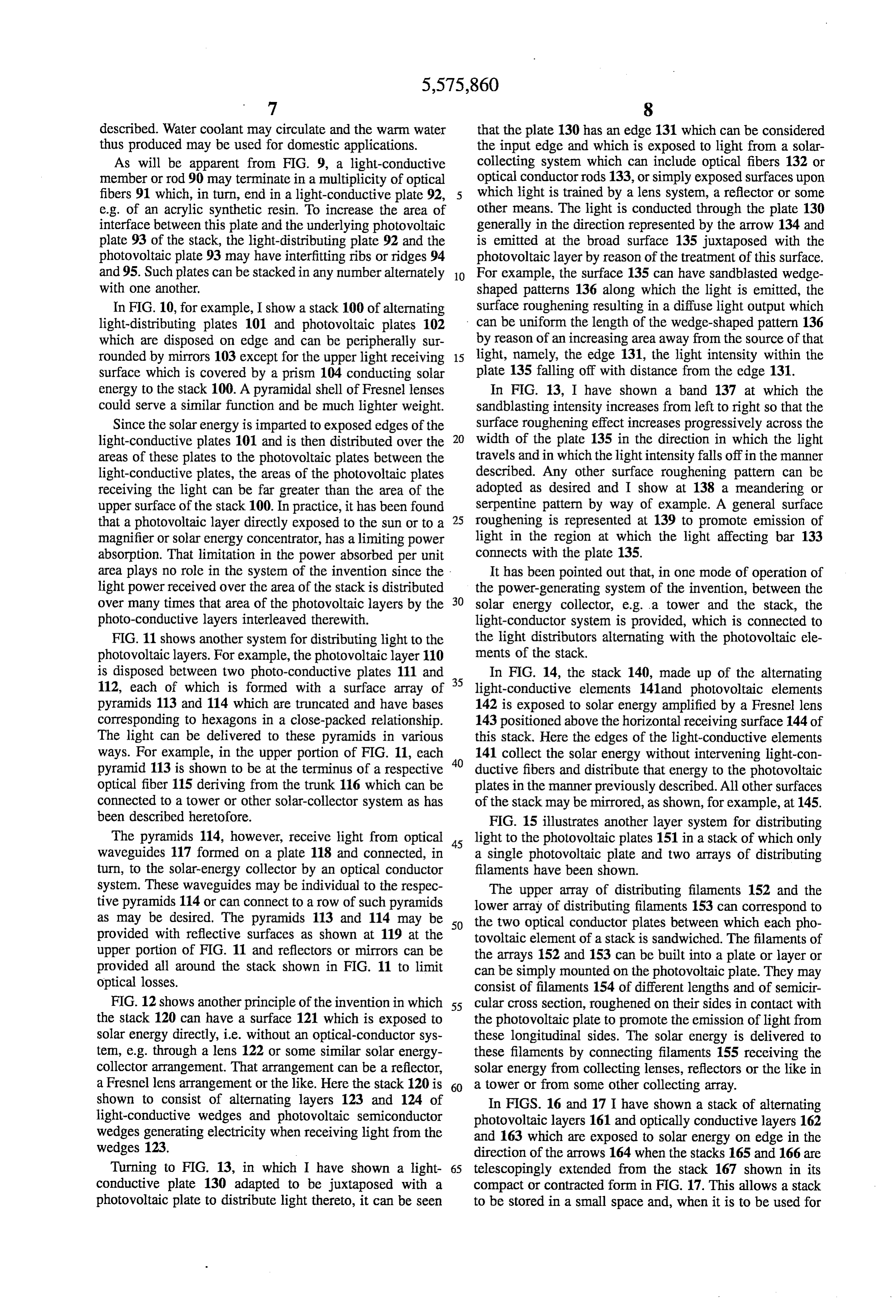
Page 16
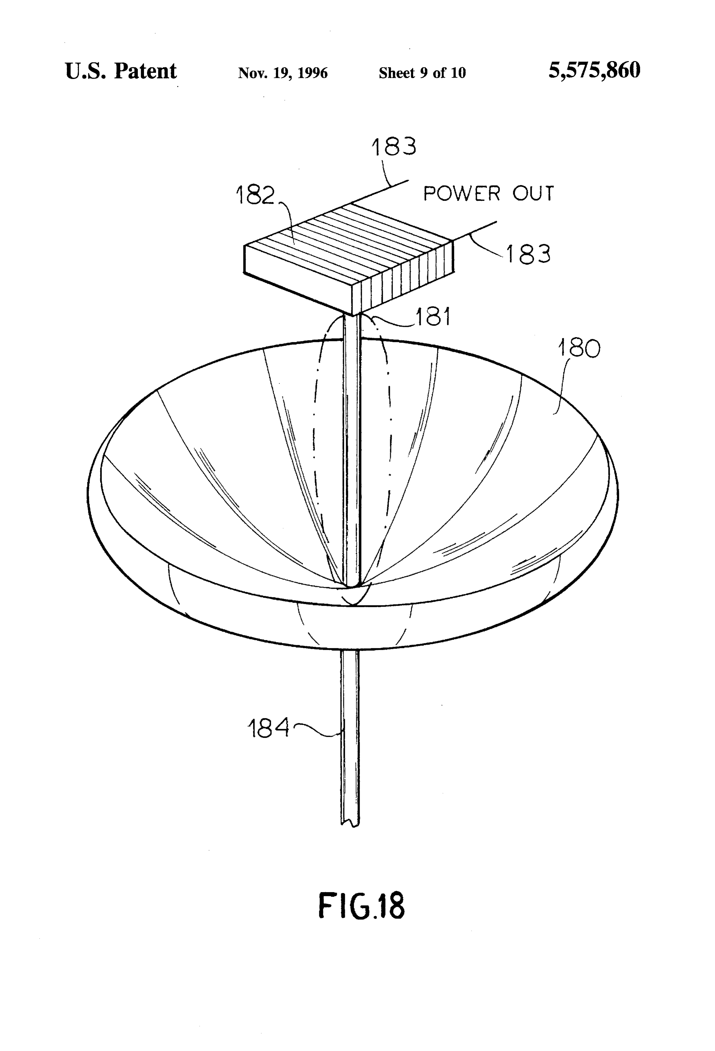
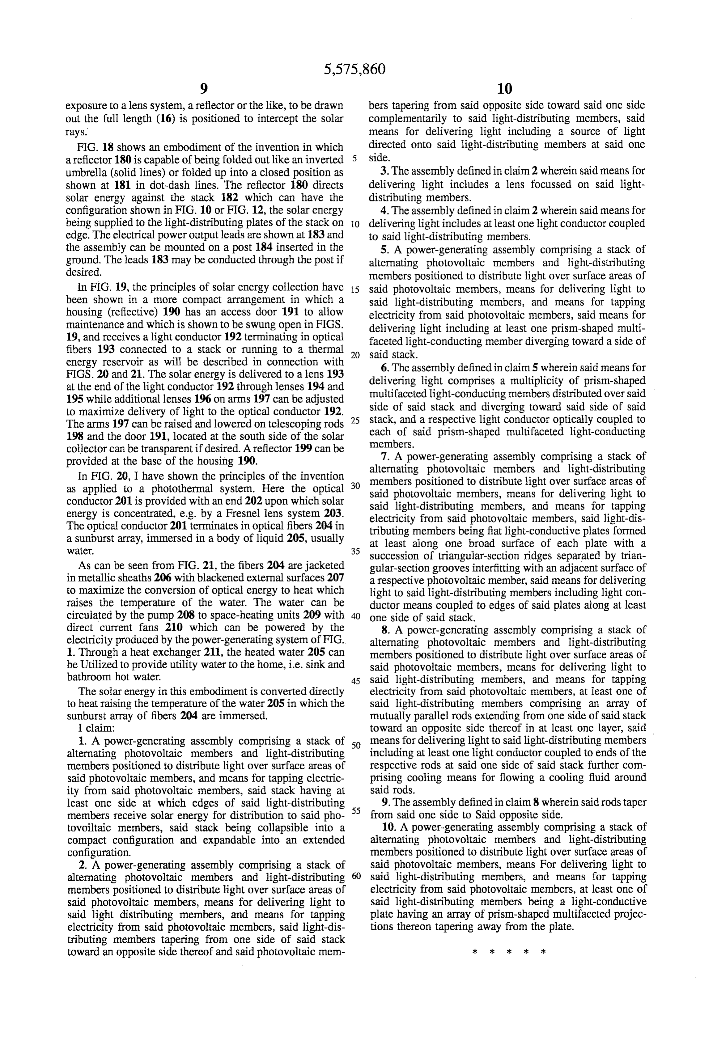
exposure to a lens system, a reflector or the like, to be drawn bers tapering from said opposite side toward said one side out the full length (16) is positioned to intercept the solar complementarily to said light-distributing members, said rays. means for delivering light including a source of light FIG. 18 shows an embodiment of the invention in which directed onto said light-distributing members at said one a reflector 180 is capable of being folded out like an inverted side.
umbrella (solid lines) or folded up into a closed position as 3. The assembly defined in claim2 wherein said means for shown at 181 in dot-dash lines. The reflector 180 directs delivering light includes a lens focussed on said light solar energy against the stack 182 which can have the distributing members.
configuration shown in FIG. 10 or FIG. 12, the solar energy 4. The assembly defined in claim2 wherein said means for being supplied to the light-distributing plates of the stack on 10 delivering light includes at least one light conductor coupled edge. The electrical power output leads are shown at 183 and to said light-distributing members. the assembly can be mounted on a post 184 inserted in the 5. A power-generating assembly comprising a stack of ground. The leads 183 may be conducted through the post if alternating photovoltaic members and light-distributing desired. members positioned to distribute light over surface areas of In FIG. 19, the principles of solar energy collection have 15 said photovoltaic members, means for delivering light to been shown in a more compact arrangement in which a said light-distributing members, and means for tapping housing (reflective) 190 has an access door 191 to allow electricity from said photovoltaic members, said means for maintenance and which is shown to be swung open in FIGS. delivering light including at least one prism-shaped multi 19, and receives a light conductor 192 terminating in optical faceted light-conducting member diverging toward a side of fibers 193 connected to a stack or running to a thermal 20 said stack.
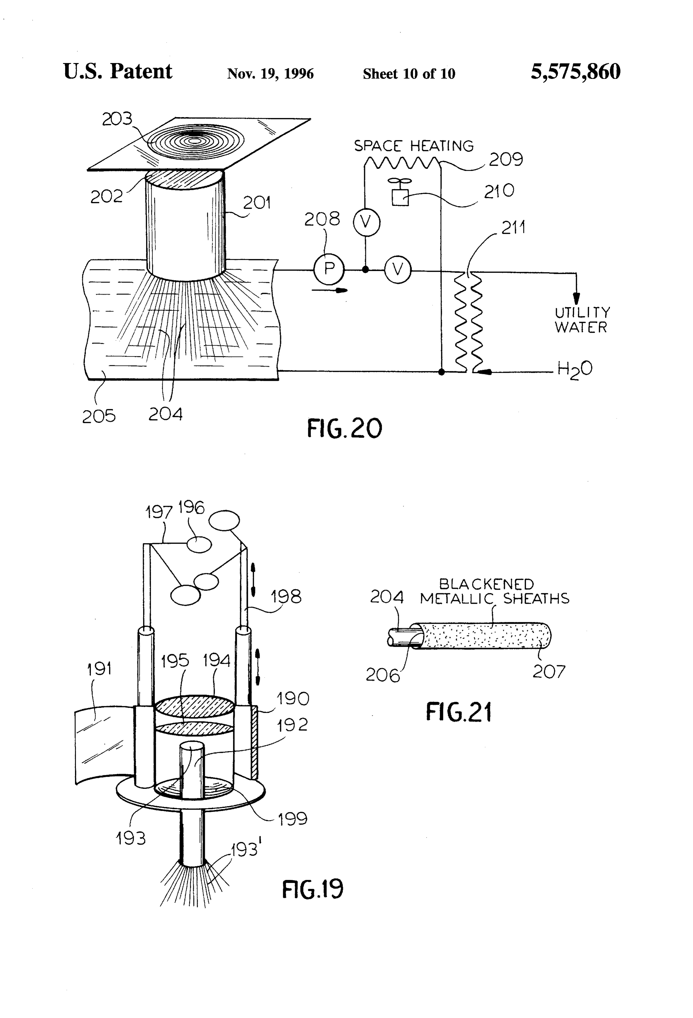
energy reservoir as will be described in connection with 6. The assembly defined in claim 5 wherein said means for FIGS. 20 and 21. The solar energy is delivered to a lens 193 delivering light comprises a multiplicity of prism-shaped at the end of the light conductor 192 through lenses 194 and multifaceted light-conducting members distributed over said 195 while additional lenses 196 on arms 197 can be adjusted to maximize delivery of light to the optical conductor 192. 25 side of said stack and diverging toward said side of said stack, and a respective light conductor optically coupled to
The arms 197 can be raised and lowered on telescoping rods each of said prism-shaped multifaceted light-conducting 198 and the door 191, located at the south side of the solar members.
collector can be transparentif desired. A reflector 199 can be 7. A power-generating assembly comprising a stack of provided at the base of the housing 190. alternating photovoltaic members and light-distributing In FIG. 20, I have shown the principles of the invention as applied to a photothermal system. Here the optical 30 members said positioned to distribute light over surface areas of photovoltaic members, means for delivering light to conductor 201 is provided with an end 202 upon which solar said light-distributing members, and means for tapping energy is concentrated, e.g. by a Fresnel lens system 203. electricity from said photovoltaic members, said light-dis The optical conductor 201 terminates in optical fibers 204 in tributing members being flat light-conductive plates formed a sunburst array, immersed in a body of liquid 205, usually at least along one broad surface of each plate with a Water. 35 succession of triangular-section ridges separated by trian
As can be seen from FIG. 21, the fibers 204 are jacketed gular-section grooves interfitting with an adjacent Surface of in metallic sheaths 206 with blackened external surfaces 207 a respective photovoltaic member, said means for delivering to maximize the conversion of optical energy to heat which light to said light-distributing members including light con raises the temperature of the water. The water can be ductor means coupled to edges of said plates along at least circulated by the pump 208 to space-heating units 209 with 40 one side of said stack.
direct current fans 210 which can be powered by the 8. A power-generating assembly comprising a stack of electricity produced by the power-generating system of FIG. alternating photovoltaic members and light-distributing 1. Through a heat exchanger 211, the heated water 205 can members positioned to distribute light over surface areas of be Utilized to provide utility water to the home, i.e. sink and said photovoltaic members, means for delivering light to bathroom hot water. 45 said light-distributing members, and means for tapping The solar energy in this embodiment is converted directly electricity from said photovoltaic members, at least one of to heat raising the temperature of the water 205 in which the said light-distributing members comprising an array of sunburst array of fibers 204 are immersed. mutually parallel rods extending from one side of said stack I claim: toward an opposite side thereof in at least one layer, said 1. A power-generating assembly comprising a stack of 50 means for delivering light to said light-distributing members alternating photovoltaic members and light-distributing including at least one light conductor coupled to ends of the members positioned to distribute light over surface areas of respective rods at said one side of said stack further com said photovoltaic members, and means for tapping electric prising cooling means for flowing a cooling fluid around ity from said photovoltaic members, said stack having at said rods.
least one side at which edges of said light-distributing 55 9. The assembly defined in claim8 wherein said rods taper members receive solar energy for distribution to said pho from said one side to Said opposite side. tovoiltaic members, said stack being collapsible into a 10. A power-generating assembly comprising a stack of compact configuration and expandable into an extended alternating photovoltaic members and light-distributing configuration. members positioned to distribute light over surface areas of 2. A power-generating assembly comprising a stack of said photovoltaic members, means For delivering light to alternating photovoltaic members and light-distributing said light-distributing members, and means for tapping members positioned to distribute light over surface areas of electricity from said photovoltaic members, at least one of said photovoltaic members, means for delivering light to said light-distributing members being a light-conductive said light distributing members, and means for tapping plate having an array of prism-shaped multifaceted projec electricity from said photovoltaic members, said light-dis tions thereon tapering away from the plate. tributing members tapering from one side of said stack toward an opposite side thereof and said photovoltaic mem ck 2 c : k
Provenance
- Collection
- Cited prior art
- Original PDF
- patentimages.storage.googleapis.com →
- Filed
- 1995-01-18
- Pages
- 16
- Method
- pdftotext (the PDF's own text layer) + pdftoppm 300dpi page scans
- Source
- Google Patents bibliographic record
- Granted
- 1996-11-19
- Inventors
- Matthew Cherney
- Transcribed from
- patentimages.storage.googleapis.com →