patent · US4358851
Fiber optic laser device and light emitter utilizing the device
9 November 1982
Page 1 — bibliographic record
le. it.
United States Patent to 11) 4,358,851 Scifres et al. 45) Nov. 9, 1982 54 FIBER OPTICLASER DEVICE AND LIGHT 4,092,659 5/1978 Ettenberg ............................. 357/18 EMITTER UTILIZING THE DEVICE 4,143,940 3/1979 Khoe .......... ... 350/96.15 4,152,674 5/1979 Taguchi .............................. 356/352 75) Inventors: Donald R. Scifres; Robert D. 4,156,206 5/1979 Comerford et al. ... ... 350/96.18 Burnham, both of Los Altos; William 4,257,671 3/1981 Barbaudy et al................. 350/96.15 Streifer, Palo Alto, all of Calif. 4,286,232 8/1981 Puech et al. ........... ... 350/96.15 X 73 Assignee: Xerox Corporation, Stamford, Conn. 4,328,468 5/1982 Krawczak et al. ................... 372/97
FOREIGN PATENT DOCUMENTS
51) Int. Cl............................................... H01S 3/082 Primary Examiner-John D. Lee 52 U.S. Cl. ...... ... 372/97; 350/96.15; Attorney, Agent, or Firm-W. Douglas Carothers, Jr. 350/96.18; 350/166; 372/6 (57) ABSTRACT 58) Field of Search ............... 350/96.15, 96.16, 96.17, A fiber optic device basically comprising an optical 350/96.18, 96.29, 164, 166,413, 416, 439, 165; fiber/interference filter combination finds useful appli 356/352; 331/94.5 C, 357/18; 372/6, 7,97, 102 cation in optical communication systems for wave 56) References Cited length selection or bandwidth selection from a multi
lSill ... . . . . . . . . . . . . . . . . . . . . . . . . . . . . . . 350/164 semiconductor laser, the. device . . may be also employed 3,803,511 4/1974 Thompson ......................... 331/94.5 E. Pri signitial mode control at the se 3,877,052 4/1975 Dixon et al. .. ... 350/96.15 ected wavelength or bandpass. 4,079,404 3/1978 Comerford ............................ 357/18 4,088,389 5/1978 Zucker et al. .................... 350/96.17 10 Claims, 15 Drawing Figures
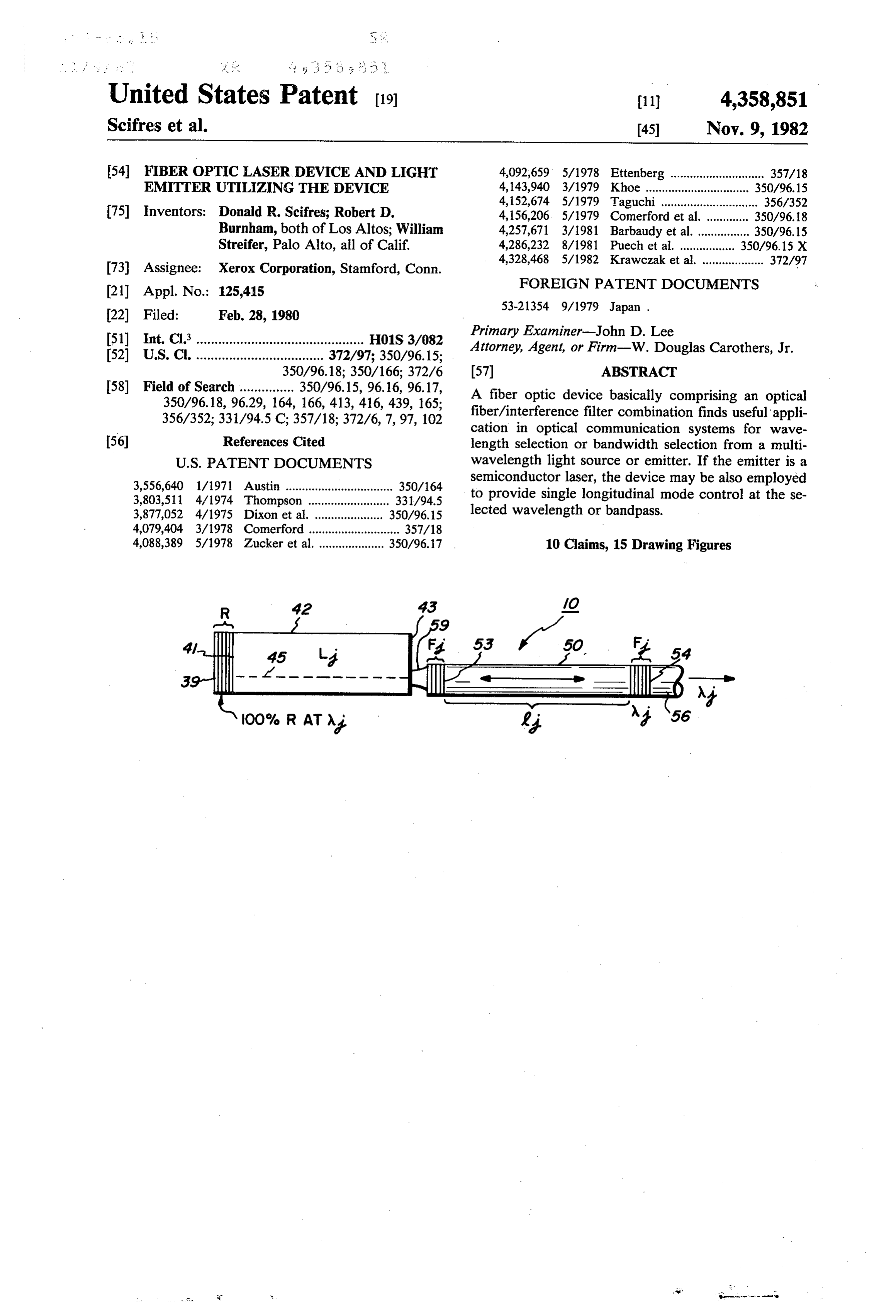
R 42 43 /O
4/ I ge 53 5O. F
s 4-F EH2 w Ali
100% R AT ?y 4 '56
--- rises:
Page 2
Drawing sheet — no readable text.
Page 3
Drawing sheet — no readable text.
Page 4
Drawing sheet — no readable text.
Page 5
Drawing sheet — no readable text.
Page 6
Drawing sheet — no readable text.
Page 7
Drawing sheet — no readable text.
Page 8
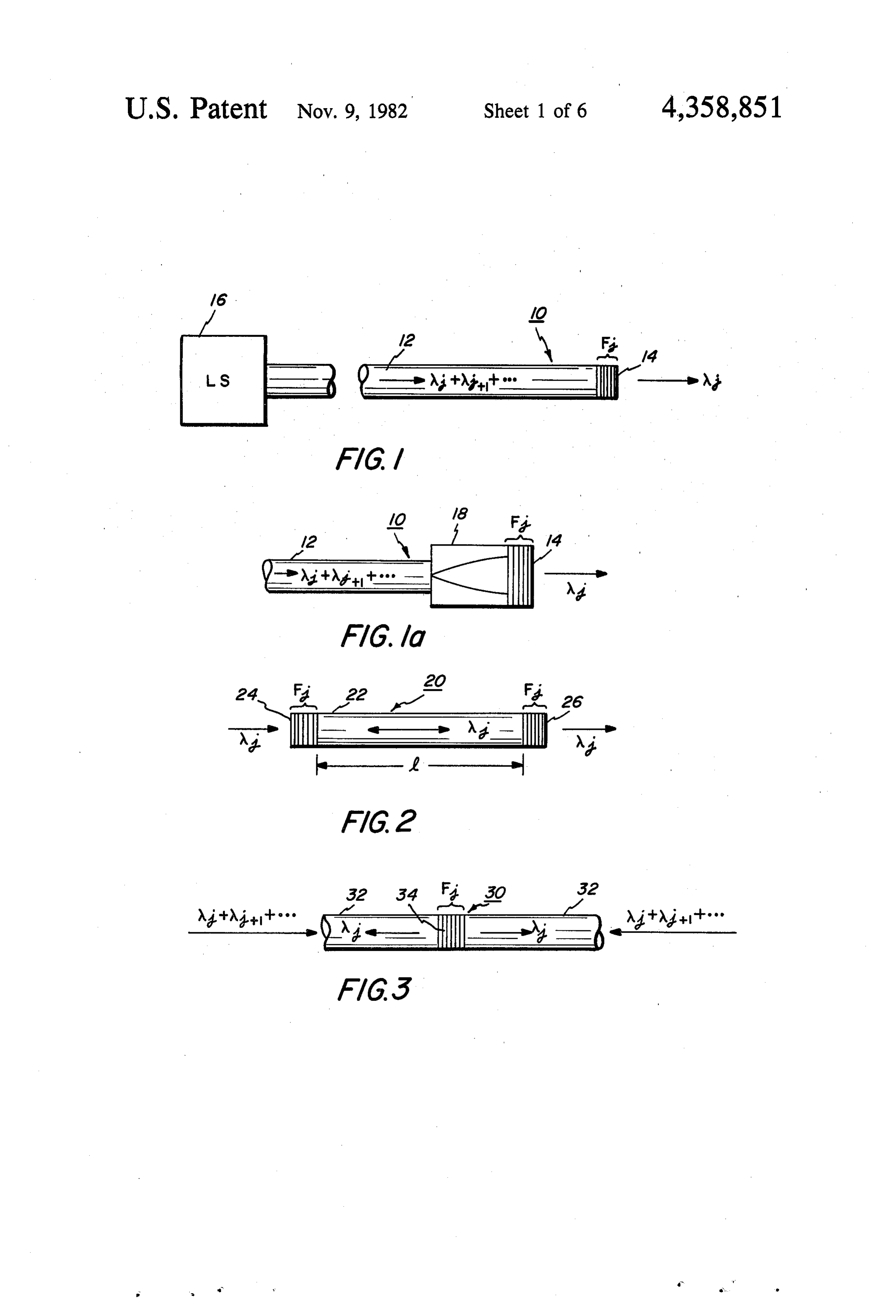
FIBER OPTCLASER DEVICE AND LIGHT BRIEF DESCRIPTION OF THE DRAWINGS EMTTER UTILIZING THE DEVICE FIG. 1 discloses a fiber optic device comprising an optical fiber with an interference filter deposited on an
BACKGROUND OF THE INVENTION 5 end portion of the fiber;
FIG. 1a is similar to FIG. 1 but, in addition includes
This invention relates to fiber optic devices for em a collimating lens between the fiber end and the filter; ployment in optical communication systems where it is FIG. 2 discloses interference filters deposited on desired to have a multiplexed wavelength transmission opposite ends of an optical fiber forming Fabry-Perot capabilities with independent light sources, which, in 10 cavity;
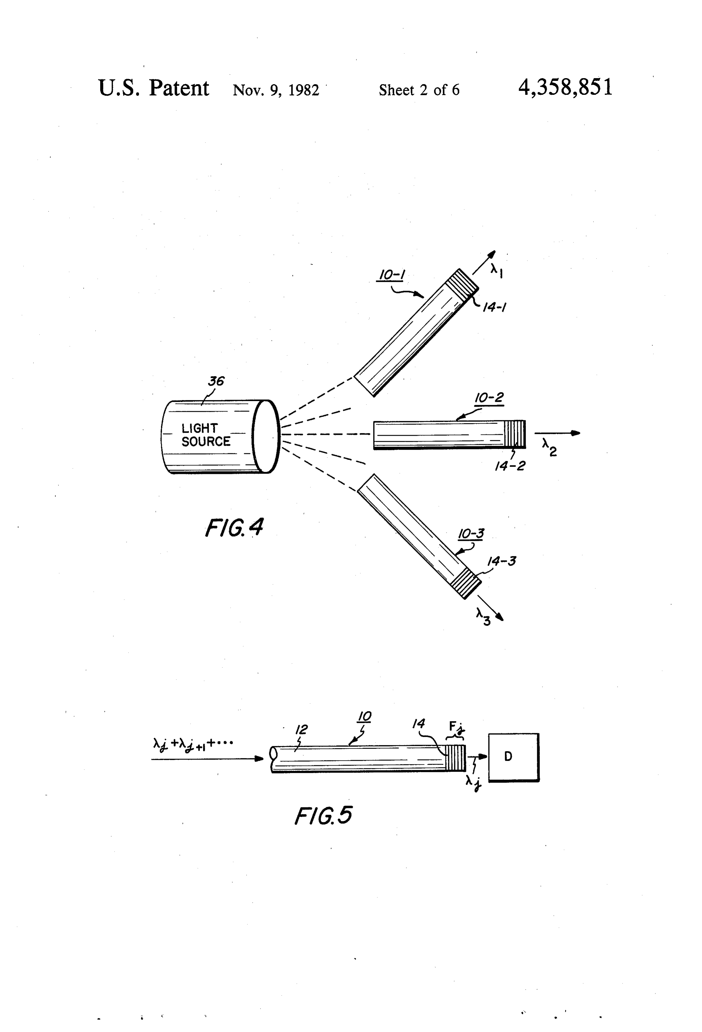
conjunction with the fiber optic devices transmit light FIG. 3 discloses a filter positioned in the length of an at a given wavelength and with independent detection optical fiber as part of a communication link; components designed to detect light at a given wave FIG. 4 discloses a multiwavelength light source with length. a plurality of fiber optic devices for passing a selected Multilayer reflectors and narrow band interference 15 wavelength emitted from the source; filters are well known in the art of optics for reflecting FIG. 5 discloses the fiber optic device of FIG. 1 used or passing light of a given wavelength or bandwidth. for detection of a selected wavelength from a multi Such filters are designed for optical communication wavelength source;
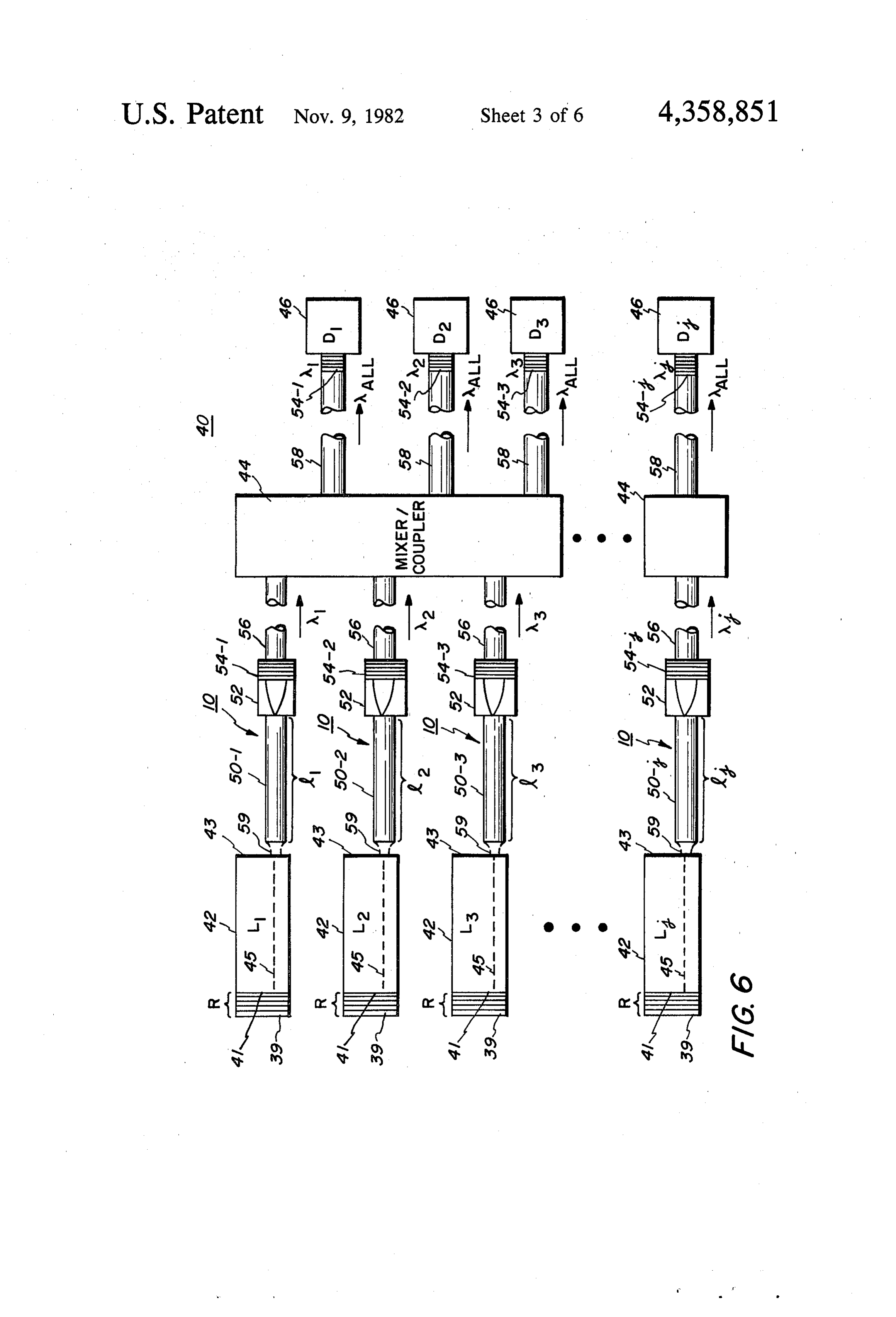
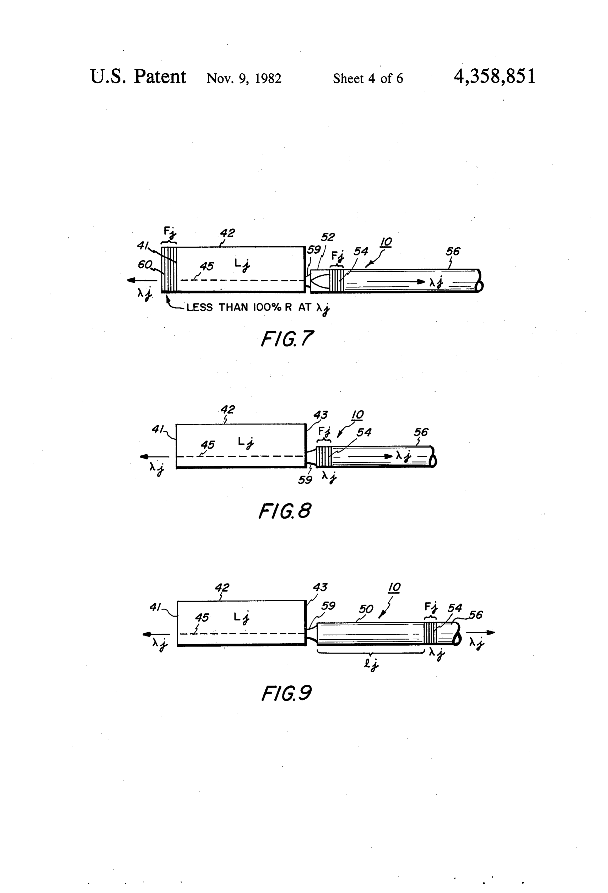
systems for passing selective wavelengths while reject FIG. 6 discloses a multi wavelength communication ing other wavelengths. Examples of such reflectors and 20 system employing the fiber optic devices of FIGS. 1 filters are disclosed in U.S. Pat. Nos. 3,037,362; through 5 and semiconductor lasers as light sources; 3,556,640; 4,092,659 and 4,099,840. FIGS. 7 through 14 disclose various alternative light Employment of such filters in optical communication source forms that may be utilized in the optical commu systems has not met with great success. The basis for 25 nication
system of FIG. 6 and in particular, discloses a semiconductor laser optically cou this invention is the practical and simple inclusion of pled to a combination fiber optic devices having narrow passband capabilities filter deposited on the collimated end of an lens and interference optical fiber;
or rejected and reflected wavelength capabilities readily adaptable in optical communication systems pled to an interference filter deposited onoptically FIG. 8 dicloses a semiconductor laser the end cou
employing, for example, semiconductor lasers, diode 30 optical fiber;
detectors, optical mixers and fiber optics. FIG. 9 discloses a semiconductor laser optically cou SUMMARY OF THE INVENTION pled at one end to a length, 1, of an optical fiber with an interference filter deposited on the other end of the
In accordance with the present invention, a fiber fiber;
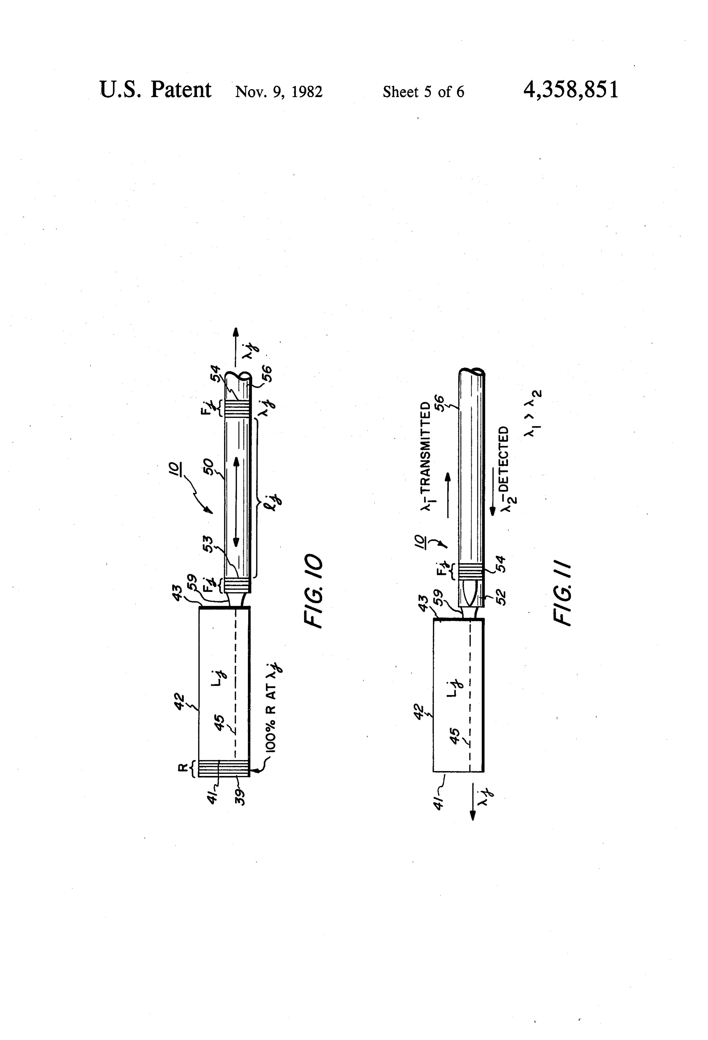
optic devices for use in an optical communication sys 35 FIG. 10 discloses a semiconductor laser optically tem is characterized by an interference filter having a coupled to a fiber optic device comprising a length, 1, of narrow bandpass or capable of passing one or more optical fiber with different interference filters deposited selected wavelengths. The filter may be a bandpass on opposite ends of the fiber;
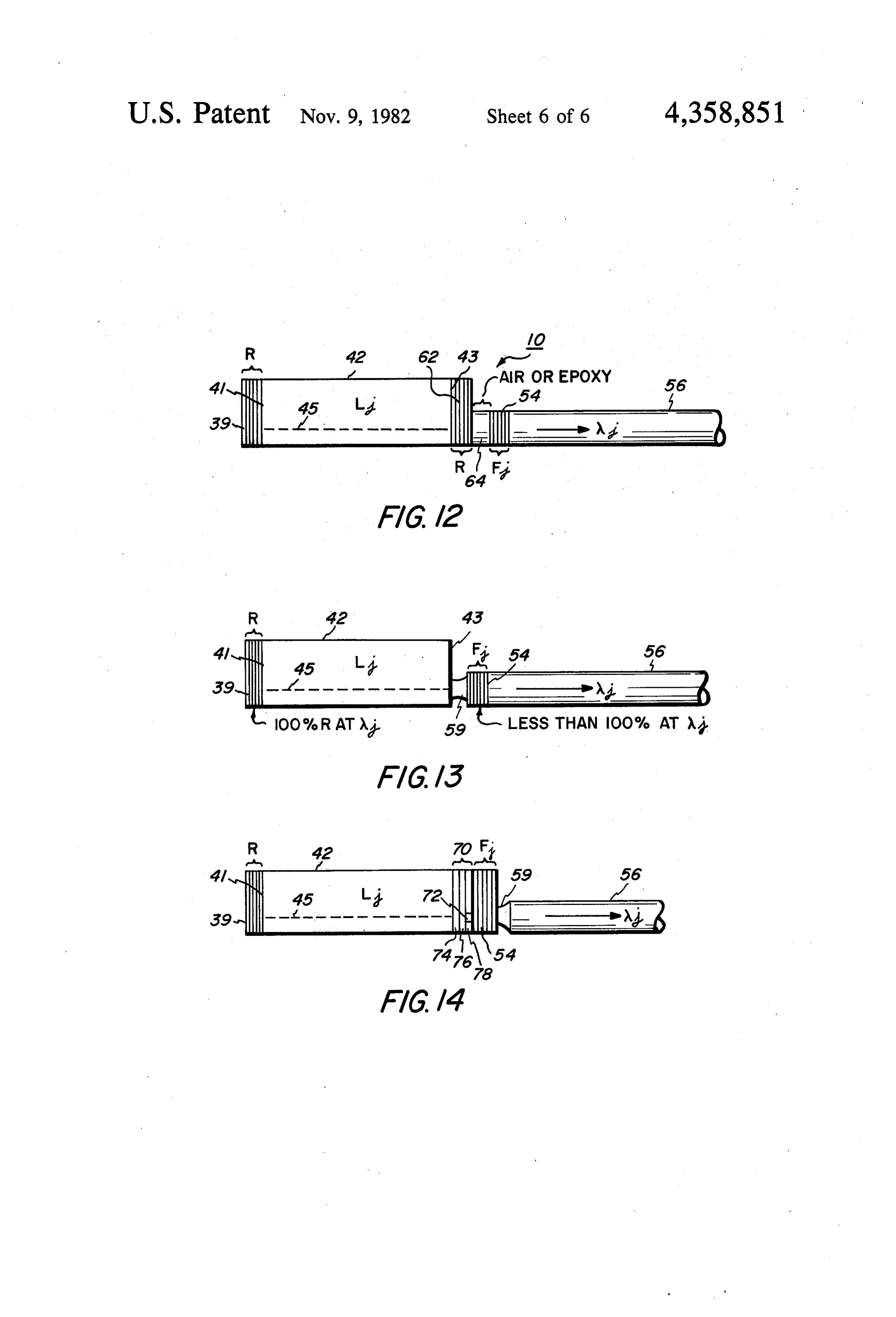
filter or bandpass reflector. The device comprises a FIG. 11 is a similar to the device shown in FIG. 7 multilayered structure deposited on the cross-sectional 40 except the device here is designed to transmit at one end of a length of optical fiber. The filter may be de wavelength and detect a different wavelength; signed to pass a selected wavelength from a source of FIG. 12 discloses a semiconductor laser optically light coupled to the optical fiber and reflect all other coupled to a spaced reflector/filter arrangement pro wavelengths back to the source. The filter may be de viding a sharp, narrow bandwidth filter; signed to reflect all wavelengths from the source and 45 FIG. 13 is similar to the device disclosed in FIG. 8 act as a partial reflector/filter for a given wavelength with the exception that the selected wavelength is also permitting part of that wavelength to be reflected and the major wavelength component in optical feedback the other part to pass into the optical communication forFIG. operation of the laser;
14 is similar to the device shown in FIG. 13 and system.
An important application for partial wavelength re 50 includes a multilayer apertured component deposited flection and passage of a particular wavelength is in filter.between the semiconductor laser and the interference connection with a light emitter such as, a semiconduc tor laser, e.g. a Ga As/Ga AlAs injection laser. The DESCRIPTION OF THE PREFERRED bandwidth of the interference filter may be designed to 55 EMBODIMENTS be within the operating wavelengths of the laser to In FIGS. 1 through 5, various arrangements are permit passage of at least a selected wavelength within shown for employment of a fiber optic device 10 which the band of optical emission from the laser while reflect comprises an optical fiber 12 having an end portion ing the remaining wavelengths to provide optical feed upon which is deposited a multilayer interference filter, back for the laser. The filtering capabilities of the filter F, shown at 14. The filter 14 comprises a plurality of can be designed either to pass a given wavelength from contiguous layers of alternating composition. Each of the semiconductor laser or a narrow bandpass of laser the layers may be approximately W/4n in thickness, A emitted wavelengths. being a free space wavelength of radiation emitted from Other objects and attainments together with a fuller the light source 16 and An is the index of refraction of understanding of the invention will become apparent 65 the particular contiguous layers deposited. Such filters and appreciated by referring to the following descrip are designed not to transmit all wavelengths of emitted tion and claims taken in conjunction with the accompa light except to be at least partially transparent to light at nying drawings. a selective wavelength, A. The filter 14 may also be
Page 9
designed to be almost totally or partially transparent to Filter 34 acts to pass wavelength, A, from either direc the wavelength, wi. The filter 14 also may be abandpass tion in the optical fiber 32.
filter or a bandpass reflector. In all cases including those The type of radiation to be employed with the fiber which follow the interaction of the fiber/filter laser optic devices 10, 20 and 30 is not limited. As illustrated combination must be such that the laser experiences in FIG. 4, the light source 36 may provide coherent or maxima of net gain at the desired outputs wavelengths. noncoherent radiation with the fiber optic devices 10-1, Thus, the filter may have to produce simultaneously 10-2 and 10-3, respectively, having interference filters low reflectivity and low transmissivity by virtue of 14-1, 14-2 and 14-3 capable of filtering wavelengths A1, selective absorption. A2 and A3. Such wavelengths may be designed to be The filter may be comprised of alternating dielectric 10 different color wavelengths from the optical spectrum. materials, such as, Al2O3, MgF2, SiO2, Si, and other FIG. 5 illustrates the fiber optic device 10 employed dielectrics and polarizable and photosensitive materials. in combination with a single detector 38, such as, a The filter may also be comprised of alternating dielec photodiode, to detect wavelength, Ni from the device tric, absorbing and/or metallic materials, such as, the 10.
above-mentioned materials and very thin layers of tellu 15 FIGS. 1-5 illustrate the range of possibilities of fiber rium, silver, gold, aluminum and bismuth for example. optic devices 10, 20 and 30. In each case an interference The fiber optic device 10 provides a unitary structure filter is deposited on one end of a section of an optical for the passage of single wavelength, Ni, or a narrow fiber.
bandpass. Most importantly, the filter/optical fiber 20 Filter deposition on the ends of the fibers is accom combination provides better wavelength selectivity and plished best by deposition in a vacuum system, the ge sharp bandpass integrity. ometry of the layers and their materials being chosen to If the light source 16 is a semiconductor laser and a provide the selected wavelength, Wii, or the selected high level of reflectivity is desired, the filter 14 may be bandpass. First, a bundle of optical fibers, such as 10,000 directly deposited on the cleaved output facet of the 25 fibers, with exposed ends are maintained in fixed rela laser. The light from the laser will not have a sufficient tion by means of dipping the fiber ends in a potting time to diverge upon exit from the laser, optimizing the material. There are suitable epoxy materials for this reflectivity upon interaction with the filter 14. The same purpose. This secures the fibers firmly together for effect may also be achieved by using a microlens 18 subsequent processing. The fiber bundle may alterna shown in FIG. 1a positioned between the end of the 30 tively be mechanically clamped together but this is not optical fiber 12 and the interference filter 14. The mi preferred because of the tendency of the fiber ends to crolens 18 with its parabolic distribution of refractive move around during subsequent processing. index will act as a lens and is employed to expand the Next, the fiber ends are polished in a polishing jig. light into a parallel collimated beam for presentation to After polishing, the potting material is removed from and interaction with the interference filter 14. 35 the vicinity of the fiber ends so that the material does The center of the lens 18 should be precisely posi not interfere with the deposition process. An organic tioned relative to the axial center of the fiber. This is solvent is used that dissolves the epoxy potting material conveniently accomplished by determining the point of but does not damage the optical fibers, such as, quartz maximum transmission through the fiber and lens and optical fibers.
then using epoxy to secure the lens 18 to the end of the 40 The optical fiber bundle is then placed in a vacuum fiber 12 while maintaining optical alignment of these chamber with the fiber ends exposed to the vapor of components. Also, an adjustable mechanical clamp as various sources of materials to be deposited and form sembly may be employed instead of an epoxy connec the filter layers. The deposition process is controlled to tion. Such mechanical couplers capable of fine adjust deposit the materials to the desired thickness on all of ment for optical alignment are known in the art. 45 the fiber ends. The sources of materials in the chamber FIG. 2 discloses a fiber optic device 20 comprising a for layers not then being deposited are masked during length, 1, of optical fiber 22, with interference filters 24 deposition of other composite layers. and 26 deposited on the opposite ends of the fiber. This After the deposition of the multilayers, the fiber bun arrangement may be designed with filters that act as dle is removed from the chamber and the individual nearly perfect reflectors for a broad range of wave 50 fibers may be easily pulled apart and separated from one lengths of radiation. Such a structure 20 can function as another due to the limited amount of remaining potting a Fabry-Perot interferometer if a single mode fiber is material.
used. Such an interferometer may be scanned in optical The fiber optic devices 10, 20 or 30 may be employed length path by a variety of techniques including bend in an optical communication system illustrated at 40 in ing of the fiber, heating of the fiber, or placing the fiber 55 FIG. 6.
in an acoustic, or electric or magnetic field. Such scan In FIG. 6, the optical communication system 40 gen ning can modulate the coherent light signal propagating erally comprises light emitters in the form of semicon through the filter as in a Fabry-Perot interferometer. In ductor lasers 42, an optical mixer/coupler 44, which addition, if a multimode fiber is used, two or more input may comprise, for example, a solid mixer rod, star cou wavelengths, A1, A2, ... Ai can be spatially separated by pler, or other low loss optical fiber transmission mixer, the Fabry-Perot interferometer owing to the different and optical detectors 46, such as, photodiodes. The opcial path lengths. A narrow band reflector/filter for lasers 42 have reflectors, R, deposited on their rear selected wavelengths of radiation, may also be designed facets 41. Reflectors 39 are fabricated to provide reflec in this configuration. In this case, two dielectric filters tion of the spontaneous emission from the laser. The are spaced by a small distance (20-50 mm) to provide a 65 dotted line 45 represents the active layer and optical narrow passband or reflector. cavity of the laser and the line of light propagation FIG. 3 discloses a fiber optic device 30, with an inter between the mirror facets 41 and 43 of the laser struc ference filter 34 positioned within an optical fiber 32. ture.
Page 10
The facet 43 has an antireflection coating applied to 42 selected for transmission. In general, the fibers may its surface to prevent facet damage due to exposure to be approximately 50 or greater in length. the ambient. This coating also increased threshold for Detectors 46 may be secured by epoxy to filters 54 or catastrophic mirror damage. The coating further in may be aligned in fixed, spaced relation relative to its creases the efficiency of extracting useful optical power respective filter.
from the facet 43. Alternative laser source arrangements for use in sys The fiber optic device 10 is coupled to a respective tem 40 are disclosed in FIG. 7-14. laser 42 by means of epoxy 59 or other suitable optical In FIG. 7, laser 42 is coupled at 59 directly to the coupling known in the art. A chemically etched well combination microlens 52 and filter 54. The light emit (not shown) may be formed in the end of the optical 10 ting region at facet 43 is centered on the optical axis of fiber 50 which is parabolic in shape. The epoxy cou the microlens 52. Filter 60 is a partial reflector at wave pling 59 will fill the formed well upon alignment with length Ai so that the selected wavelength emission can the cavity 45 of the laser 42. This provides a convex lens also be detected from facet 41. arrangement formed by the epoxy itself with the fiber 15 The configuration of FIG. 8 is the same as FIG. 7 well for more efficient coupling of the laser light into except that the filter 60 is not present. Thus, a portion of the fiber 50. In such an arrangement, the fiber 50 has a all spontaneous emission from the laser 42 is present at lower index of refraction than the epoxy coupling mate the rear facet 41. Also, the microlens 52 is not utilized in rial. the fiber optic device 10. This represents one of the The end of the fiber 50 may be provided with a spher 20 simplest forms for the fiber optic device 10. ical lobe larger in extent than the diameter of the fiber. In FIG. 9, the configuration shown is the same as those
The lobe is epoxy coupled to the laser or light emitter present, shown in FIG. 6 except that the reflector 39 is not and forms a converging lens for emitted light. In such permitting all spontaneous emission to be de an arrangement, the fiber 50 has a higher index of re employed.from tectable facet 41. Also, the microlens 52 is not
The length, 1, of the optical fiber 50 may be fraction than that of the lobe.
Each fiber optic device 10 in FIG. 6 comprises an 25 selected to provide a mode locked wavelength, Aj. optical fiber section 50 of specific length, a microlens 52 10Inis the
FIG. 10 the combination laser/fiber optic device and an interference filter 54. The optical fiber has a additionalsame as those shown in FIG. 6 except that an specific length, 1, to provide a Fabry-Perot cavity be optical fiberfilter 53 is deposited on the other end of the section 50. Filter 53 is designed to pass a tween the mirror facet 43 of the laser 42 and the inter 30 portion of N while relecting the remaining portion ference filter 54. This cavity comprises two reflectors morestrongly separated by a distance, 1, the laser facet 43 represent tion for opticalthan other emitted wavelengths of radia ing one reflector and the interference filter 54 represent pass almost 100% of N or Filter feedback. 54 may be designed to ing the other reflector. Facet 43 reflects a portion of the than 100% of A to render fiber opticdesigned may be device to pass less 10 a Fabry spontaneous emission from the laser 42 for laser feed 35 Perot cavity for fine tuning of the longitudinal mode back while the filter 54 has maximum reflectivity of operation of laser 42 at Wi.
spontaneous emission from the laser 42 back into the The structure shown in FIG. 11 is the same as that of filter cavity 50 of the selected wavelength, A1, A2, A3, . FIG. 7 except that the rear facet 41 of laser 42 does not ... or a selected narrow bandpass. Wavelength A repre sents a primary wavelength in the spontaneous emission includedesigned the partial filter 60 and, further, the filter 54 is to have a filter response for A1, the major from each of the lasers 42. Simultaneously each filter wavelength of spontaneous emission from laser 42, also transmits some portion of this wavelength. where A1 is greater than A2. Laser 42 may be reverse The advantage of employing the device 10 with the biased to act as a detector for A2 eminating from another laser 42 is that a very sharp selected wavelength filter light source in an optical communication system con can be fabricated to provide a second Fabry-Perot reso 45 nected to optical fiber 56. For this purpose, an antire nator that will impose longitudinal mode restrictions on flection coating may be provided on the surface of laser the laser 42 and simultaneously pass a desired wave facet 43 so that A2 will readily couple into the laser length into an optical communication link. The desired optical cavity 45. Laser 42, operating as a detector, can wavelength may be data modulated via pulse operation absorb wavelength A2 since it has a shorter wavelength of laser 42. Laser mode control is important in optical 50 than its major wavelength A1. Filter 54 may be de communication systems. Longitudinal mode control signed, for example, to be reflective for 50% to 70% of means frequency stabilization and efficient operation at A but have no reflective response for A2. A sensing the selected wavelength employed in the system. circuit (not shown) sensitive to A2 may be its detectable The material output of devices 10 of system 40 are optical input, such as a photodiode, positioned at filter coupled by optical fibers 56 to mixer/coupler 40 where 55 54 and operative to reverse the bias on laser 42 when A2 the wavelengths of light are commingled for transfer to is detected in optical fiber 56. With the bias reversed, various destinations in the system or for optical cou laser 42 will respond similar to a photodiode. pling into other systems. Destinations are represented The configuration of FIG. 12 permits the develope by the optical fibers 58 coupling the optical output of ment of narrow and sharp bandpass filtering. A partial the mixer/coupler 40 to detectors 46. Although all com 60 reflector 62 is positioned at the emitting region of laser mingled wavelengths of light appear on each of the facet 43. Filter 54 is deposited on the end of fiber 56 fibers 58, filters 54 pass only the designed wavelength or having a filter pass for wi. The device 10 is coupled to bandpass for detection by the detector 46. In the repre the partial reflector 62 in space relation, indicated at 64, sentation of FIG. 6, filters 51-1 are designed to pass which may be accomplished by a mechanical coupler or wavelength M1; filters 54-2, wavelength A2; filters 54-3, 65 by epoxy. As an example, the spacing 64 may be about wavelength 3, etc. Also optical fibers 50 are designated 10p to 50p. The reflector 62 may transmit, for example, 50-1; 50-2, 50-3, ... 50-j to indicate that their lengths, 1, 50% to 70% of the spontaneous emission of the laser 42, will vary depending on the wavelengths from the laser the remaining portion of which is reflected back as
Page 11
optical feedback for the laser. The facet 43 may be such alternatives, modifications, and variations as fall provided with an antireflection coating to increase cou within the spirit and scope of the appended claims. pling efficiency. What is claimed is:
The arrangement in FIG. 12 provides for a very 1. A solid state laser capable of producing a con narrow bandpass, such as 10A to 20A wide. The spaced trolled narrow wavelength of emission and including a reflector 62 and filter 54 act as spaced reflectors for a radiation generating medium within a first optical cav portion of the laser spontaneous emission forming a ity, a passive waveguide medium forming a second secondary optical cavity generally represented by the optical cavity, said cavities being optically coupled spacing 64. This provides single longitudinal mode op together, reflector means at the extremities of said cav eration for the laser 42. The laser 43 operates with a 10 iies and at the point of their coupling, at least one of said certain set of lasing frequencies within a given band reflector means being a narrow band reflector having a width. The Fabry-Perot cavity 64, being in addition to peak reflectivity within the gain spectra of radiation the laser cavity 45, imposes new restrictions on this set emission from said medium whereby a dual cavity is of frequencies in a manner that certain lasing wave established selective of a narrow band of operating lengths interfere constructively to produce major high 15 wavelengths.
intensity wavelengths. Filter 54 is designed to pass the 2. The laser according to claim 1 wherein there is at major wavelength, Wi. least one additional optical cavity optically coupled to In FIG. 13, the configuration is the same as that in said second optical cavity.
FIG. 8 except reflector 39 is deposited on facet 41 of 3. The laser according to claim 1 wherein said laser laser 42. Reflector 39 is designed to provide almost 20 produces a periodic optical pulse train, the pulses 100% reflection at facet 41 for the Niemission from laser therein occurring at a time interval determined by the
In FIG. 14, the laser 42 includes an apertured compo round trip propagation of radiation in said optical cavi nent 70 deposited on facet 43 of laser 42. Filter 54 is then ties.4. The laser according to claim 3 wherein said time deposited on component 70 followed by coupling of 25 interval between said pulses may be varied by varying optical filter 56 to filter 54 by means of epoxy 59. the effective length of at least one of said optical cavi The apertured component 70 comprises a dielectric ties.
trilayer disclosed in detail in patent application Ser. No. 5. The laser according to claim 1 including means to 064,698 filed Aug. 8, 1979 entitled "Apertured and Un effectively apertured Reflector Structures for Electroluminescent said secondvary 30 the length of the optical path through optical cavity whereby the wavelength of
Devices' and assigned to the assignee herein (now U.S. said laser may be selectively adjusted.
respectively, comprise Al2O3, Si and Te. The ablation waveguide 6. The laser according to claim 1 wherein said passive of layer 78 is accomplished by operation of laser 42 medium comprises a single mode optical using its optical power to form an aperture 72. The 35 fiber, emitted radiation from laser 42 is at the highest intensity 7. The laser according to claim 1 wherein said passive at aperture 72 so that the laser will operate with its waveguide medium comprises a multimode optical fi lowest light loss in the region of aperture and provide ber.
stabilization in its operation in the fundamental trans 8. The laser according to claim 1 including a micro verse mode while providing a wavelength Ni of signifi collimating lens forming said second optical cavity, one cantly undiverged properties. of said reflector means being formed directly on said The incorporation of the fiber optic device 10 as lens.
shown in either of FIGS. 6 or 9 between the filter 54 9. The laser according to claim 1 including a micro and the optical fiber 56 in FIG. 14, would provide both collimating lens within said second optical cavity, one fundamental transverse and longitudinal mode control 45 of said reflector means being formed directly on said for laser 42 at the selected wavelength, i. lens.
Each of the reflectors 39 in FIGS. 10, 12, 13 and 14 10. The laser according to claim 1 wherein the reflec may readily be replaced by the partial wavelength filter tor means between said optical cavities has an aperture 60 discussed and shown in FIG. 7. formed through a portion of said reflector means, said While the invention has been described in conjunc 50 aperture being in alignment with said optical cavities tion with specific embodiments, it is evident that many whereby said laser will operate with lowest radiation alternative modifications and variations will be appar loss in the region of said aperture and whereby stable ent to those skilled in the art in light of the foregoing fundamental transverse mode operation is achieved. description. Accordingly, it is intended to embrace all sk k k sk :k
Provenance
- Collection
- Cited prior art
- Original PDF
- patentimages.storage.googleapis.com →
- Filed
- 1980-02-28
- Pages
- 11
- Method
- pdftotext (the PDF's own text layer) + pdftoppm 300dpi page scans
- Source
- Google Patents bibliographic record
- Granted
- 1982-11-09
- Inventors
- Donald R. Scifres; Robert D. Burnham; William Streifer; Xerox Corp
- Transcribed from
- patentimages.storage.googleapis.com →