patent · US4942736
Method of and apparatus for producing power from solar energy
24 July 1990
Page 1 — bibliographic record
United
Bronicki
States Patent (19 11 Patent Number: 4.942,736
54 METHOD OF AND APPARATUS FOR tus for producing power from solar energy wherein a PRODUCING POWER FROM SOLAR solar collector heats gas supplied to a gas turbine; com ENERGY pressors compress the gas, the gas being compressed 75 Inventor: Lucien Y. Bronicki, Yavne, Israel and stored gas during a first period of time, with the stored compressed gas being supplied to the gas turbine 73 Assignee: Ormat Inc., Sparks, Nev. during a second period of time to produce power by 21 Appl. No.: 246,149 driving an electric generator. Preferably, the first per (22 Filed: Sep.19, 1988 iod of time is during periods of off-peak electricity, which normally occur at night. The second period of 51) Int. Cl. ................................................ F03G 7/02 time is during the day. The solar collector preferably 52 U.S. C. .............................. 60/641.12; 60/641.15; comprises tracking reflectors for focusing solar radia 60/652; 60/655; 60/659; 60/676; 60/682 tion and a receiver for receiving the focused solar radia 58) Field of Search ............. 60/641.8, 641.11, 641.12, tion and also heating the gas. The solar radiation re 60/641.13, 641.14, 641.15, 650, 655, 659, 664, ceiver preferably comprises a rotating ceramic member. 676, 682, 652 Furthermore, a combustion chamber is preferably pro (56) References Cited vided to heat the gas entering the gas turbine and is
the solar radiation received by the receiver is insuffi 4,189,922 2/1980 Bellofatto ......................... 60/659 X cient to heat the gas entering the gas turbine to the 4,581,897 4/1986 Sankrithi ...... ... 60/641.15 X required temperature. The electric motor used to oper 4,765,142 8/1988 Nakhamkin....................... 60/659 X ate the compressors preferably comprises the electric FOREIGN PATENT DOCUMENTS generator of the gas turbine. Furthermore, heat gener 105606 8/1979 Japan ................................ 60/641.14 ated during the compression of the gas and contained 148907 11/1980 Japan ..................................... 60/655 therein is transferred to another fluid in a heat ex Primary Examiner-Stephen F. Husar changer which comprises part of waste heat converter Attorney, Agent, or Firm-Sandler, Greenblum & for producing electrical power therefrom. Bernstein
The present invention provides a method of and appara 36 Claims, 3 Drawing Sheets
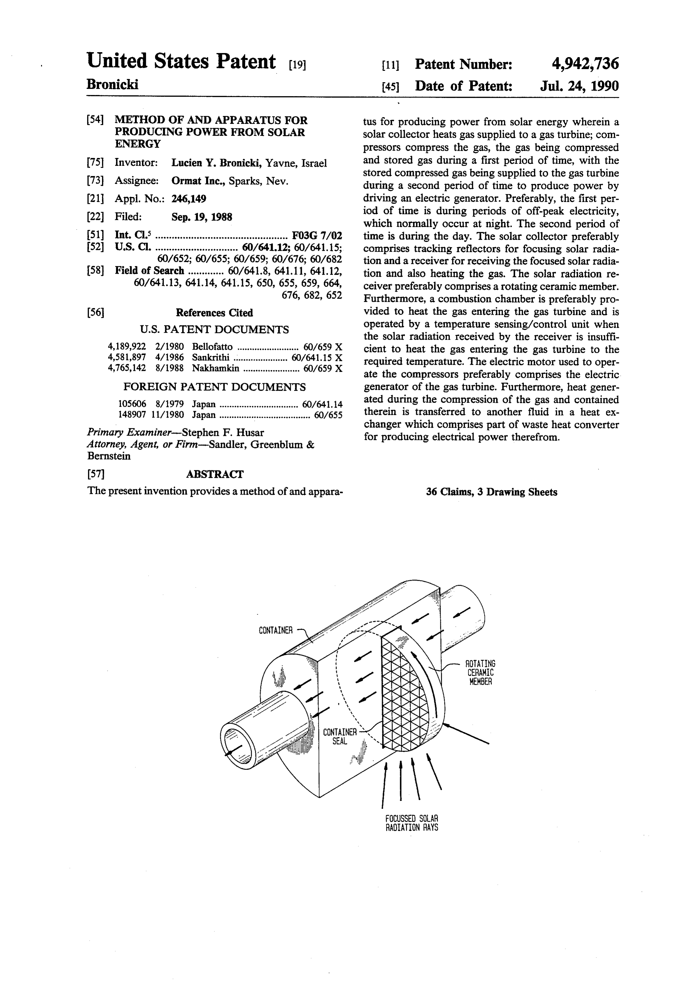
ROTATING
CERAMIC
MEMBER
CONTAINERS
SEA
FOCUSSED SOLAR
RADIATION RAYS
Page 2
Drawing sheet — no readable text.
Page 3
Drawing sheet — no readable text.
Page 4
Drawing sheet — no readable text.
Page 5
/control unit when the solar radiation received by the
METHOD OF AND APPARATUS FOR receiver is insufficient to heat the gas entering the gas PRODUCING POWER FROM SOLAR ENERGY turbine to a required temperature. Normally, the gas used is air. However, other suitable gases may be used.
TECHNICAL FIELD An electric motor is used to operate the compressors This invention relates to producing power from solar and preferably comprises the electric generator of the energy and more particularly is concerned with a gas turbine. In a preferred embodiment, the compressor method of and apparatus for producing power from is a multi-stage compressor and the gas turbine is a Solar energy using a gas turbine. multi-stage turbine. Furthermore, heat generated dur O ing the compression of the gas and contained therein is
BACKGROUND OF THE INVENTION transferred to another fluid in a heat exchanger which In recent years, the domestic, commercial and indus preferably is part of a waste heat converter for produc trial power consumption, in many countries, particu ing electrical power, the waste heat converter being an larly at hours of peak power consumption, has been Organic Rankine Cycle power plant in one embodi growing at a seemingly ever increasing rate. Since elec 15 ment. Thus, in the present invention, available solar tric power utility companies are obligated to furnish energy is utilized to produce electricity, further cutting power demand at the level required even if such power costs by also preferably compressing gas used in the gas consumption levels occur infrequently for only a few turbine during periods of relatively cheap off-peak elec hours a day, the generating power capacity of the elec tricity.
tric utility companies must be such as to provide power 20 at the required power level whenever called upon. Nor BRIEF DESCRIPTION OF THE DRAWINGS mally, and particularly in many countries in the summer Embodiments of the invention are described below time, hours of peak power consumption occur during by way of example, and with reference to the accompa the day with consumption levels falling to their so nying drawings wherein:
called "off-peak” levels during the night. 25
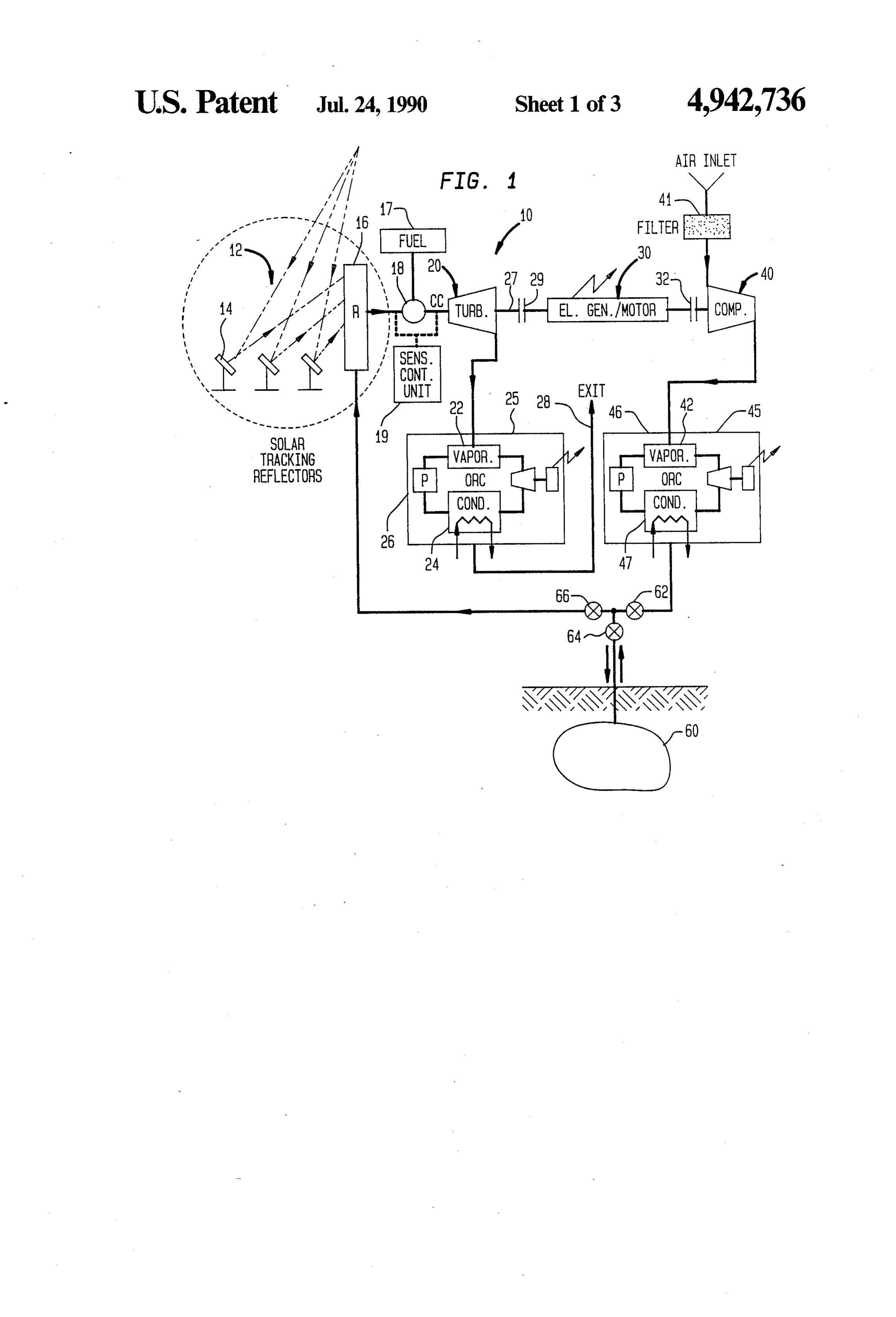
FIG. 1 is a block diagram of one embodiment of
Since the peak power demands on the electric utility apparatus for producing power in accordance with the companies occur only for relatively short periods of present invention;
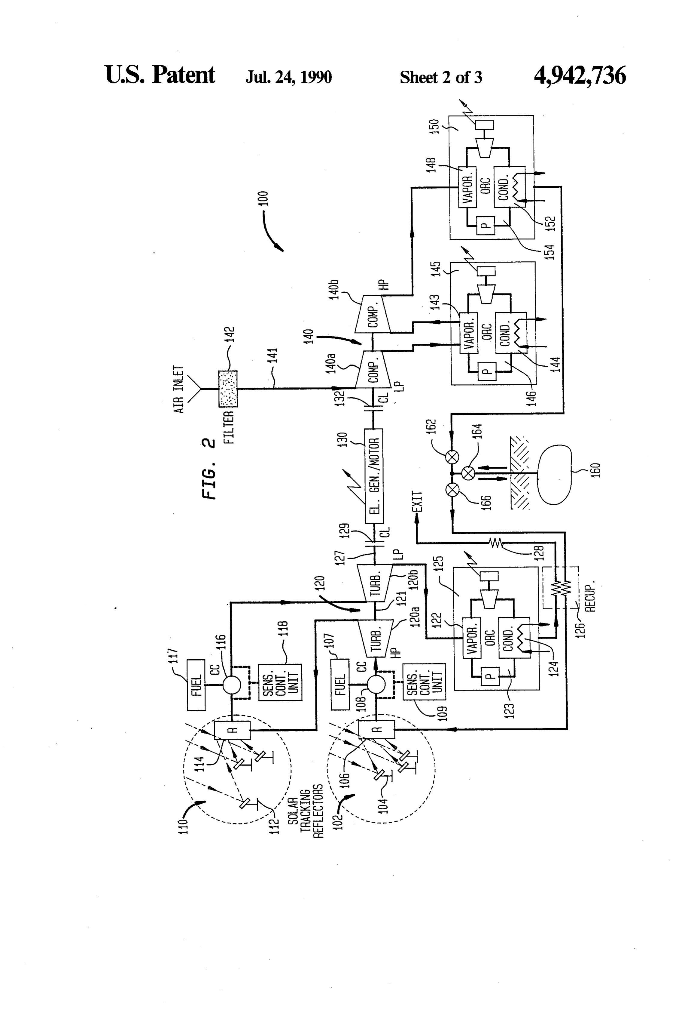
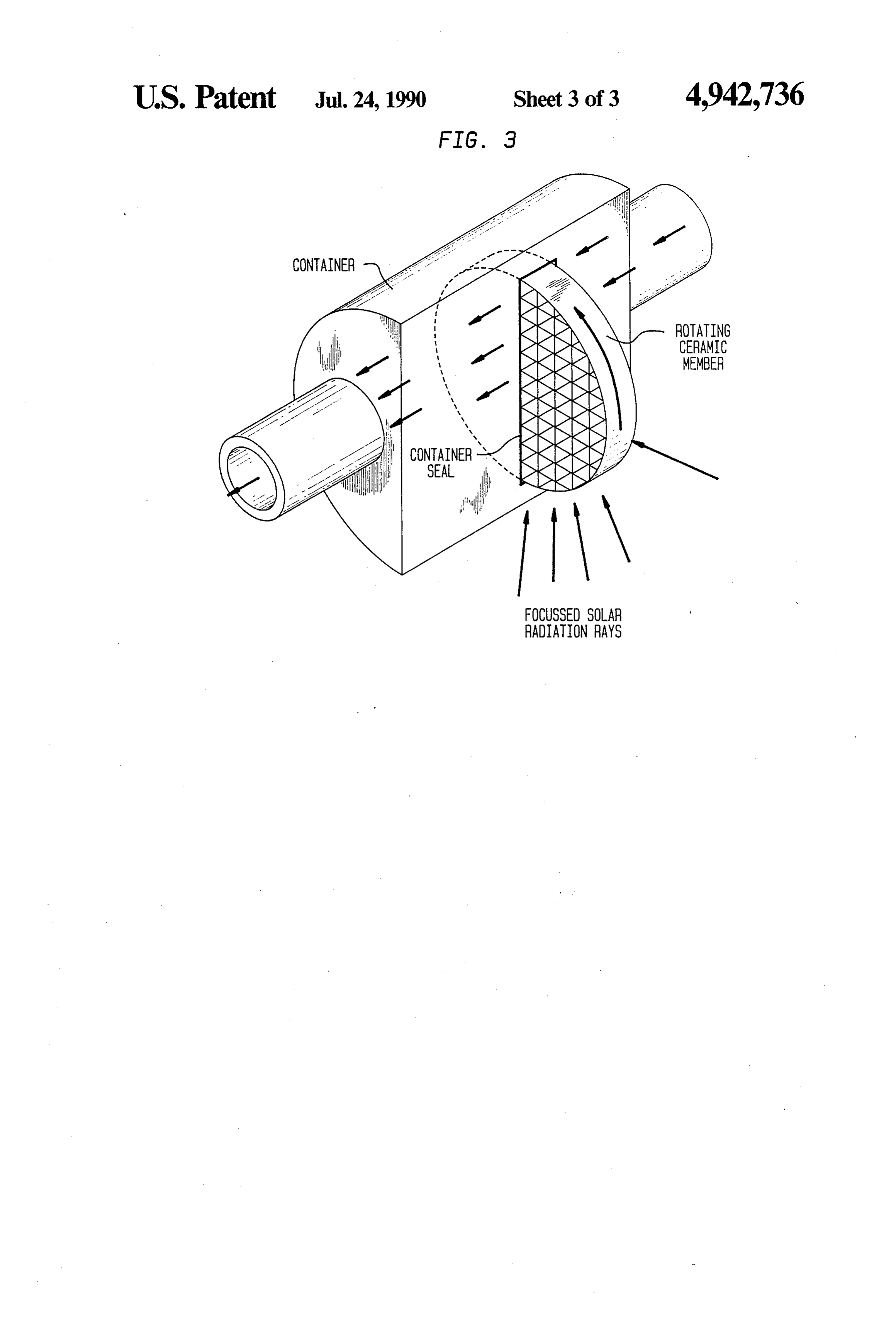
time, the electric utility conventionally operates gener FIG. 2 shows a schematic diagram of a further em ating plants having minimal costs and reasonably low bodiment operating costs, for example coal burning plants to sup 30 FIG. 3 isofa the present invention and perspective view showing details of a solar ply the base load and intermediate load of customers connected to the electric grid with more expensive receiver according to the present invention. operating plants such as gas turbines being quickly DETAILED DESCRIPTION brought onto line to furnish power during the short Referring to FIG. 1 of the drawings, reference nu periods of peak demand. Consequently, the cost of peak 35 meral 10 designates apparatus for producing power in power is normally several times larger than the cost of what is called baseload or "off-peak' power. accordance with the present invention. Solar collector It is therefore an object of the present invention to 12, comprising tracking reflectors 14 or heliostats for provide a new and improved method of and apparatus focusing solar radiation and solar radiation receiver 16 for producing electrical power during periods of peak for receiving focused solar radiation, is provided for power demand wherein the disadvantages as outlined heating compressed air supplied from underground including and related to the relatively large costs are storage reservoir 60 to gas turbine 20, the compressed reduced or substantially overcome. air being stored in underground storage reservoir 60 during the operation of compressor 40. Gas turbine 30
SUMMARY OF THE INVENTION 45 drives electric generator/motor 20, operating as an The present invention provides a method of and ap electric generator, for producing electric power sup paratus for producing power from solar energy, the plied to the electric grid (not shown). If preferred, how method comprising the steps of heating gas supplied to ever, a separate electric generator can be used. Mirror a gas turbine using a solar collector; compressing the reflectors can serve as tracking reflectors, and receiver gas during a first period of time using a compressor; 50 16 is normally positioned at the top of a tower. In the storing the compressed gas during the first period of present invention, existing caverns, such as artificial salt time in a storage reservior and supplying the com caverns and underground aquifers can be used as stor pressed gas from the storage reservior to the gas turbine age reservoirs for storing compressed air. Also quite during a second period of time to produce power by often underground caverns located in geological fields driving an electric generator. Preferably, the first per 55 where oil wells exist are suitable for use as storage reser iod of time is during periods of off-peak electricity, voirs and many times existing oil wells such as dry and which normally-occurs at night. Off-peak electricity old ones etc., can also be utilized in the present inven periods of time are periods of time when the price of tion. Heat exchanger 22 contained in waste heat con electricity is relatively cheap. The second period of verter 25 receives heat present in air exhausting turbine time is during the day. The solar collector preferably 60 20, and waste heat converter 25 produces electrical comprises tracking reflectors for focusing solar radia power therefrom. Preferably, waste heat converter 25, tion and a receiver for receiving the focused solar radia comprises Organic Rankine Cycle (ORC) power plant tion and also heating the gas. The solar radiation re 26 containing vaporizer heat exchanger 22 and con ceiver preferably comprises a rotating member prefera denser 24 cooled by cooling water. Heat received in bly constructed from ceramic material. 65 heat exchanger vaporizes working fluid of the power In addition, combustion chambers are also preferably plant, the vaporized working fluid being furnished to a provided for heating the gas entering the gas turbine turbine for producing electric power. Subsequently, the and are preferably operated by a temperature sensing expended air exits via exhaust conduit 28. Combustion
Page 6
chamber 18, run on fuel supplied from fuel tank 17 and pors exhausted from this turbine are condensed in con located between receiver 16 and turbine 20, is provided denser 47 which is cooled by cooling water, a feed for maintaining a desired temperature of the air entering pump returning the condensed organic fluid to vapor the gas turbine. Preferably, combustion chamber 18 is izer heat exchanger 42. During the day, the stored com operated by sensing/control unit 19. Air exiting re pressed air present in storage reservoir 60 is made avail ceiver 16 flows through combustion chamber 18 to gas able by opening valves 64 and 66 and flows toward turbine 20. Alternatively, air exiting solar receiver 16 turbine 20 flowing through solar radiation receiver 16 can flow directly to turbine 20 via suitable conduits, where focused solar radiation reaching receiver 16 from avoiding passage through the combustion chamber tracking reflectors 14 heats the compressed air normally when the air temperature is sufficient, and can be di 10 to more than several hundred degrees centigrade, the verted by using suitably arranged valves and piping to air reaching preferably a temperature of 800 deg. C. also flow through the combustion chamber when this is However, higher temperatures can be used if required. brought into operation. Compressor 40, which com Subsequently, the heated, compressed air flows through presses air supplied through filter 41, is driven by elec combustion chamber 18 reaching gas turbine 20 where tric generator/motor unit 20. If preferred, a separate 15 expansion takes place. Expansion in turbine 20 causes electric motor can be used to drive the compressor. the turbine to do work, rotating shaft 27 and driving Heat exchanger 42, contained in waste heat converter electric generator/motor 20, now acting as an electric 45, receives heat present in air compressed in compres generator and coupled thereto via clutch 29 producing sor 40, and the waste heat converter produces electrical electric power which is supplied to the electric grid. power therefrom during the operation of the compress 20 Electric generator/motor 20 is disconnected from com ers. Preferably, waste heat converter 45, comprises pressor 40 by clutch 32. If the temperature of the air Organic Rankine Cycle (ORC) power plant 46 contain exiting solar receiver 16 drops below a desired value ing vaporizer heat exchanger 42 and condenser 47 due, for example, to the presence of cloud cover reduc cooled water. The heat received by heat exchanger 42 ing the amount of focused radiation reaching the re vaporizes the working fluid of the power plant, these 25 ceiver, sensing/control unit 19 senses the temperature vapors being supplied to the power plant turbine driv drop of the air and brings combustion chamber 18 into ing a generator for producing electrical power, with the operation in order to heat the air to maintain the tem expended vapors being condensed by condenser 47. perature of air entering turbine 20. Heat remaining in In the present embodiment, solar receiver 16 can the air or gases exiting gas turbine 20 is received by heat comprise a sealed container having pipes connected to 30 exchanger 22 and used to produce electric power via the compressed air flow and positioned at the focus of power plant 26 in a manner similar to that which takes the tracking reflectors for receiving focused solar radia place in power plant 46 described above. Subsequently, tion and heating the compressed air which flows the expended gas exiting via conduit 28. Consequently, through the pipes. Temperatures and pressures in the in the present invention, solar energy is utilized to pro pipes can reach 1000 deg. C. and 50 bar or even higher. 35 duce electric power using a gas turbine, the compressed Preferably, however, the solar receiver may have the air used to run the gas turbine being compressed and configuration shown in FIG. 3. The receiver comprises stored during periods of off-peak electricity, thus taking a sealed container connected to the compressed airflow advantage of the relatively cheap cost electricity during and a rotating member, a portion of which is positioned such periods. Furthermore, quite often, the periods of external to the sealed container at the focus of the track time during which electric power is produced by the ing reflectors for receiving the focused solar radiation, gas turbine coincides with periods of peak electric the member also rotating within the sealed container power consumption.
where the heat absorbed by the member heats the com Referring now to FIG. 2, a further embodiment of pressed air flowing past the rotating portion of the the present invention is shown wherein reference nu member in the container. In the preferred construction 45 meral 100 designates apparatus for producing power of this member, ceramic material is used and the mem from solar energy. This embodiment is similar to the ber has a matrix form. Also, the seals of the container embodiment shown in FIG. 1 except that multi-stage are preferably cooled by a gas or air flow. gas turbine 120 and a multi-stage compressor 130 are In operation, compressor 40 driven by electric used, with second solar collector 110 and a further generator/motor 20 compresses air supplied through 50 waste heat converter 145 being provided between the filter 41, the compressed air being stored in reservoir 60 stages of the multi-stage turbine and compressor respec by opening valves 62 and 64. Preferably, the air is com tively in order to raise the efficiency of the power gen pressed to a pressure of between 30 to 50 bar, with such erating apparatus. Also, recuperator heat exchanger 126 a pressure being also maintained in the air storage reser provides additional heating of the compressed air sup voir. The compressor is operated during periods of 55 plied to gas turbine 120. The gas turbine can have a off-peak electricity in order to take advantage of the generating capacity of 25MW or greater. However, the relatively cheap cost of electricity during such periods present embodiment is also suitable for smaller generat of time. Normally, such periods of time occur during ing capacities as well. Solar collector 102, comprising the night and consequently electric generator/motor 20 tracking reflectors 104 or heliostats for focussing solar is made available for use, acting as an electric motor radiation and solar radiation receiver 106 for receiving running compressor 40. Heat generated during com focused solar radiation, is provided for heating com pression and present in the compressed air is received pressed air, the air being compressed by compressor 140 by heat exchanger 42 and used to produce electric and stored in underground storage reservoir 126 during power via power plant 46 wherein the heated air passes the operation of multi-stage compressor 140, with the through heat exchanger 42 vaporizing an organic work 65 compressed air being supplied to multi-stage gas turbine ing fluid, such as Freon or the like, the vapors being 120 from storage reservoir 126. Turbine 120 drives supplied to the turbine contained in power plant 46 for electric generator/motor 130, operating as an electric driving a generator and producing electric power. Va generator, for producing electric power supplied to the
Page 7
electric grid (not shown). If preferred, however, a sepa ing electric power therefrom. As can be seen from FIG. rate electric generator can be used. As in the embodi 2, waste heat converter 150 preferably comprises Or ment described with reference to FIG. 1, mirror reflec ganic Rankine Cycle power plant 154. tors can be used as tracking reflectors and receiver 106 Similar to solar receiver 16 described in relation to is normally positioned at the top of a tower. Combus the previous embodiment shown in FIG. 1, solar receiv tion chamber 108, located between receiver 106 and ers 106 and 114 in the present embodiment also can turbine 120, is provided for maintaining the desired comprise a sealed container having pipes positioned at temperature level of the air entering the gas turbine and the focus of the tracking reflectors for receiving fo is run on fuel supplied from fuel tank 107, the combus cussed solar radiation and heating the compressed air or tion chamber being preferably operated by sensing 10 gases which flow through the pipes with operating /control unit 109. Air exiting receiver 106 flows temperatures and pressures in the pipes possibly reach through combustion chamber 108 to gas turbine 120. In ing 1000 deg. C. and 50 bar or even higher. However, the present embodiment, multi-stage gas turbine 120, operating temperatures and pressures of gases or air in comprises high pressure stage turbine 120a and low receiver 114, positioned between the stages of the gas pressure stage turbine 120b whereas multi-stage com 15 turbine 120 could be lower than these. Preferably, how pressor 140 comprises low pressure stage compressor ever, also, solar receivers 106 and 114 comprise a rotat 14.0a and high pressure compressor 140b operated by ing member a portion of which is positioned external to electric generator/motor 130, which operates as an a sealed container at the focus of the tracking reflectors electric motor. If preferred however, a separate electric for receiving the focussed solar radiation, the member motor can be provided for compressor 140. Solar col 20 also rotating within the sealed container where it trans lector 110, comprising tracking reflectors 112 or helio fer heat to the compressed air or gases flowing past the stats for focussing solar radiation and solar radiation rotating portion of the member in the container. Also receiver 114 for receiving focused solar radiation, is here, the member is preferably constructed from ce provided for reheating air or gas exiting high pressure ramic material with the member having a matrix form stage turbine 120a with combustion chamber 116, being 25 and the seals of the container being preferably cooled preferably being operated by sensing/control unit 118 by a gas or air when necessary and run by fuel supplied from fuel tank When compressors 140a and 140b driven by electric 117 to maintain the temperature of the gases or air en generator/motor 130 commence operation, air supplied tering low pressure stage turbine 120b. In this manner, through filter 142 via conduit 141 to the compressors is the efficiency of gas turbine 18 is improved. Also here, 30 compressed to a pressure of between 30 to 50 bar, the mirror reflectors can be used as tracking reflectors and compressed air being stored at similar pressure in reser receiver 114 is normally positioned at the top of a voir 160 by opening valves 162 and 164. In a similar tower. Air or gases exiting receiver 114 flow through manner to the previous embodiment, th compressors are combustion chamber 116 to low pressure stage gas tur operated during periods of off-peak electricity taking bine 120b. Alternatively, gases can flow directly to 35 advantage of the relatively cheap cost of electricity turbines 120a and 120b from solar receivers 106 and 14 during such periods of time. Normally, such periods of via suitable conduits, avoiding passage through com time occur during the night and consequently permit bustion chambers 108 and 116 when the air or gas tem ting electric generator/motor 130 to operate as an elec perature is sufficient, and be diverted to also flow tric motor running compressors 140a and 140b. Heat through the combustion chambers by suitable piping generated during compression and present in the com and valve arrangements when the combustion chambers pressed air is received heat exchangers 143 and 148 and are brought into operation. Heat exchanger 122, con is used to produce electric power using power plants tained in waste heat converter 125 receives heat present 146 and 154 in a manner analogous to power plants 26 in air or gases exiting low pressure stage turbine 120b, and 46 contained in the previous embodiment shown in and waste heat converter 125 produces electrical power 45 FIG. 1. During the day, stored compressed air is made therefrom. As shown in FIG. 2, waste heat convertor available from storage reservoir 160 by opening valves 125 preferably comprises Organic Rankine Cycle 166 and 164 and flows toward multi-stage turbine 120 (ORC) power plant 123, whereas in such case heat flowing through recuperator heat exchanger 126 and exchanger 122 comprises a vaporizer for vaporizing the solar radiation receiver 106 where focussed solar radia working fluid of the power plant, these vapors being 50 tion reaching receiver 106 from tracking reflectors 104 supplied to a turbine contained therein for producing heats the compressed air normally to more than several electrical power, the expended vapors exiting the tur hundred degrees centigrade, the gases reaching prefera bine being condensed in condenser 124 cooled by cool bly a temperature of 800 deg. C. If necessary, however, ing water. Recuperator heat exchanger 126 is provided also in the present embodiment, higher temperatures for utilizing residual heat remaining in air or gases leav 55 can be used. This heated compressed air now flows ing power plant 123 to preheat the compressed air sup through combustion chamber 108 reaching high pres plied from storage reservoir 160 to solar receiver 106. sure stage turbine 120a where expansion takes place. Exhaust conduit 86 furnishes an exit for the expended Expanded gases exhausted from turbine 120a flow air or gases to the ambient air. In the present embodi through receiver 114 and combustion chamber 116 ment, heat exchanger 143, contained in waste heat con where they are heated once again to relatively high verter 145, preferably comprising Organic Rankine temperatures of several hundred degrees, the heated Cycle power plant 146 wherein heat exchanger 143 is a gases being subsequently supplied to low pressure stage vaporizer, is provided for producing electrical power turbine 120b where expansion occurs once again. Dur from heat contained in compressed air exhausting from ing expansion, turbines 1.20a and 120b do work, and low pressure stage compressor 140a. In addition, waste 65 shaft 121 and shaft 127 respectively are rotated thereby, heat converter 150, containing heat exchanger 148 for driving electric generator/motor 130, now acting as an receiving heat present in compressed air exiting high electric generator producing electric power. Shaft 127 pressure stage compressor 140b is provided for produc is coupled to electric generator/motor 130 via clutch
Page 8
129 and disconnected from compressor 140 by clutch of the gas exiting the solar receiver below a predeter 132. If the temperature of the air or gases exiting either mined value.
solar receivers 106 and 114 drops below a desired value, 10. A method according to claim 2 including the step sensing/control units 109 and 118 sense the temperature of extracting work from the gases exhausted from the drop of the air or gases and bring combustion chambers turbine.
108 and 116 respectively into operation for maintaining 11. An apparatus for producing power from solar the temperature of gases or air entering turbines 120a energy using a gas turbine for driving an electric gener and 120b. Gases exiting low pressure stage turbine 120b ator comprising: compressor means for compressing flow to heat exchanger 122 of Organic Rankine Cycle gas: a storage reservoir for storing gas compressed by power plant 123 where heat contained therein is used to 10 said compressor means during a first period of time: a vaporize the working fluid of this power plant, such as solar collector for heating gas from the reservoir: and Freon etc., the vapors being supplied to the power plant means for supplying gas from the storage reservoir to turbine to produce electric power by driving a genera the turbine through said solar collector during a second tor. Vapors exiting the power plant turbine are con period of time to produce power by driving the electric densed in condenser 124 cooled by cooling water with 15 generator and producing electricity. a feed pump returning the condensed organic fluid to 12. An apparatus according to claim 11 wherein said heat exchanger 122. Further heat contained in gases or for first period of time is during periods of off-peak demand air exiting power plant 123 are used in recuperator 126 electricity.
to heat compressed airflowing from air reservoir 160 to 20 13. Apparatus according to claim 11 wherein said receiver 106. Expended gases are exhausted from appa first period of time is during the night and said second period of time is during the day.
ratus 100 via exhaust conduit 128.
It is believed that the advantages and improved re ing14.a Apparatus heat according to claim 11 further compris exchanger for cooling the compressed gas.
sults furnished by the method and apparatus of the pres ent invention are apparent from the foregoing descrip 25 15. Apparatus according to claim 14 wherein said tion of the embodiments of the invention. Various heat exchanger is part of a waste heat converter for changes and modifications may be made without de producing 16.
electrical power.
Apparatus according to claim 14 wherein said parting from the spirit and the scope of the invention as waste heat converter is an Organic Rankine Cycle described in the claims that follow.
What is claimed is: power plant and said heat exchanger is a vaporizer for 1. A method for producing power from solar energy 30 vaporizing
Rankine the organic working fluid of the Organic
Cycle power plant.
comprising the steps of: compressing gas from an ambi 17. Apparatus according to claim 11 wherein said ent source during a first period of time and storing the solar collector comprises tracking reflectors for focus compressed gas in a storage reservoir; and supplying ing solar radiation and a receiver said compressed gas from the storage reservoir to a gas 35 of a tower for receiving the focusedpositioned solar at the top radiation and turbine through a solar collector during a second period heating the gas.
time to produce electricity.
2. A method according to claim 1 wherein first period ing18.a combustion
Apparatus according to claim 17 further compris of time coincides with periods of off-peak demand for plying it to the gaschamber turbine. for heating gas prior to sup electricity. 19. Apparatus according to claim 18 wherein the 3. The method according to claim 1 wherein said first solar radiation receiver and combustion chamber are period of time is during the night and said second period arranged such that the gas flowing to said gas turbine of time is during the day.
4. The method according to claim 1 further compris passes chamber.
through the solar receiver and said combustion ing the step of cooling the compressed gas prior to 45 20. Apparatus according to claim 17 wherein said storing it by supplying heat present in the compressed solar radiation receiver comprises a rotating ceramic gas to another fluid in a heat exchanger. member.
5. The method according to claim 4 further compris 21. Apparatus according to claim 11 further compris ing producing electric power using heat supplied to said ing an electric motor for driving said compressor. fluid in said heat exchanger, said heat exchanger being 50 22. Apparatus according to claim 21 wherein said part of a waste heat converter. electric motor comprises the electric generator driven 6. The method according to claim 5 wherein said heat by the gas turbine during the second period of time. supplied to the fluid is used to vaporize the fluid, the 23. Apparatus according to claim 11 wherein said gas vapors being supplied to a turbine contained in said turbine is a multi-stage turbine and said compressor is a waste heat converter to produce electric power, said 55 multi-stage compressor.
waste heat converter being an Organic Rankine cycle 24. Apparatus according to claims 11 wherein said power plant. gas is air.
7. The method according to claim 1 further compris 25. Apparatus according to claim 19 further compris ing the step of heating the gas prior to supplying it to ing a sensing/control unit for sensing the temperature of said turbine using a combustion chamber. the gas exiting the solar receiver and for sending a sig 8. The method according to claim 7 wherein said nal to the combustion chamber to commence operation solar collector comprises tracking reflectors for focus when the temperature of the gas falls below a predeter ing solar radiation and a receiver positioned at the top mined value.
of a tower for receiving the focused solar radiation, said 26. An apparatus according to claim 11 including a receiver being used to heat the gas. 65 means responsive to heat in the gases exhausted from 9. The method according to claim 8 further compris the gas turbine for generating power.
ing the step of commencing operation of said combus 27. An apparatus for producing power from solar tion chamber in response to sensing a fall in temperature energy comprising:
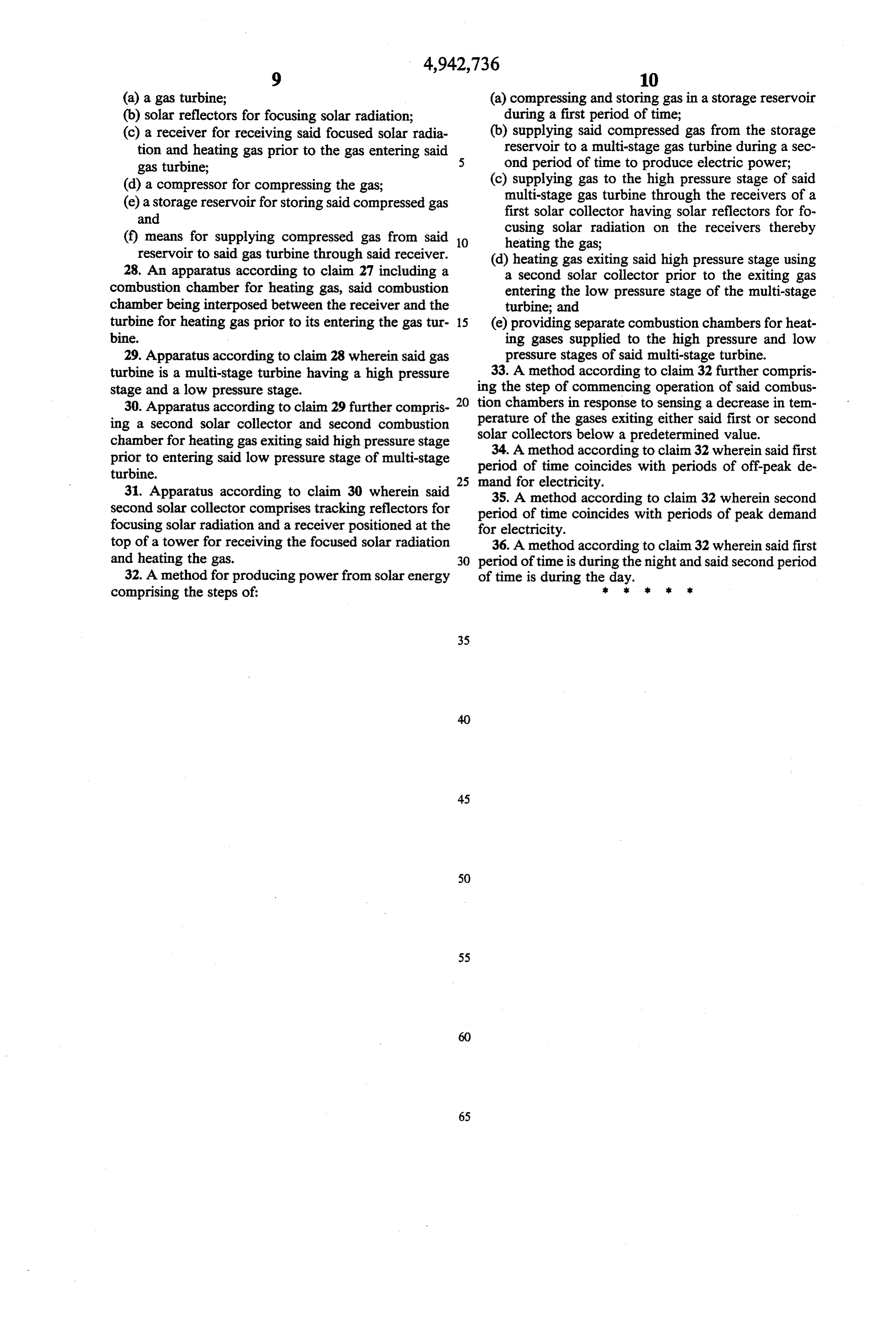
Page 9
(a) a gas turbine; (a) compressing and storing gas in a storage reservoir (b) solar reflectors for focusing solar radiation; during a first period of time; (c) a receiver for receiving said focused solar radia (b) supplying said compressed gas from the storage tion and heating gas prior to the gas entering said reservoir to a multi-stage gas turbine during a sec gas turbine; ond period of time to produce electric power; (d) a compressor for compressing the gas; (c) supplying gas to the high pressure stage of said (e) a storage reservoir for storing said compressed gas multi-stage gas turbine through the receivers of a and first solar collector having solar reflectors for fo (f) means for supplying compressed gas from said O cusing solar radiation on the receivers thereby heating the gas;
reservoir to said gas turbine through said receiver. (d) heating gas exiting said high pressure stage using 28. An apparatus according to claim 27 including a a second solar collector prior to the exiting gas combustion chamber for heating gas, said combustion entering the low pressure stage of the multi-stage chamber being interposed between the receiver and the turbine; and turbine for heating gas prior to its entering the gas tur 15 (e) providing separate combustion chambers for heat bine. ing gases supplied to the high pressure and low 29. Apparatus according to claim 28 wherein said gas pressure stages of said multi-stage turbine. turbine is a multi-stage turbine having a high pressure 33. A method according to claim 32 further compris stage and a low pressure stage. ing the step of commencing operation of said combus 30. Apparatus according to claim 29 further compris 20 tion chambers in response to sensing a decrease in tem ing a second solar collector and second combustion perature of the gases exiting either said first or second chamber for heating gas exiting said high pressure stage solar collectors below a predetermined value. 34. A method according to claim 32 wherein said first prior to entering said low pressure stage of multi-stage period of time coincides with periods of off-peak de turbine. 25 mand for electricity.
31. Apparatus according to claim 30 wherein said 35. A method according to claim 32 wherein second second solar collector comprises tracking reflectors for period of time coincides with periods of peak demand focusing solar radiation and a receiver positioned at the for electricity.
top of a tower for receiving the focused solar radiation 36. A method according to claim 32 wherein said first and heating the gas. 30 period of time is during the night and said second period 32. A method for producing power from solar energy of time is during the day.
comprising the steps of: :
Provenance
- Collection
- Cited prior art
- Original PDF
- patentimages.storage.googleapis.com →
- Filed
- 1988-09-19
- Pages
- 9
- Method
- pdftotext (the PDF's own text layer) + pdftoppm 300dpi page scans
- Source
- Google Patents bibliographic record
- Granted
- 1990-07-24
- Inventors
- Lucien Y. Bronicki; Ormat Inc
- Transcribed from
- patentimages.storage.googleapis.com →